Supplement Water Saving System Installation, Maintenance, Operation and Programming Instructions Supplement Refer to Page 3 for Model Identification NOTA: El manual en español aparece después del manual en inglés. UW UF Q027I Q027IE3A Keep These Instructions for Future Reference. (If this machine changes ownership, this manual must accompany machine.) Part No.
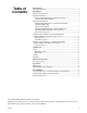
Table of Contents Introduction......................................................................................... Model Identification ............................................................................. 3 3 Installation........................................................................................... Dimensional Clearance......................................................................... Machine Foundation ....................................................................
Notes 2 F232122
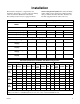
Introduction Model Identification Information in this manual is applicable to these models: UW 60 PV UW 100 PV UF 35 PV UF 50 PV UF 85 PV F232122 3
Notes 4 F232122
Installation This manual is designed as a supplement to the installation, maintenance, operation and programming of PV model Pocket Hardmount and Cabinet Freestanding washer-extractors equipped with the Water Saving System (WSS). This manual should be used in addition to the information found in manuals with part numbers F232084, F232089, F232058 and F232059 (supplied with the washer-extractor).
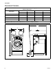
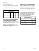
Installation Dimensional Clearance UWPV Pocket Hardmount with Water Saving System Machine Dimensions* 60 100 Dimensions in. mm in. mm A 4-7/16 1052.5 47-1/16 1195.4 B 91 2311 95-5/8 2428.9 C 61-3/4 1568 73-1/4 1861 D 15-3/4 400 15-3/4 400 * Allow a minimum of 24 inches (610 mm) at the rear and 18 inches (460 mm) at the sides for maintenance, inspection and adjustment. Allow at least 18 inches (460 mm) between machines in multiple installations.
Installation UFPV Cabinet Freestanding with Water Saving System Machine Dimensions* 35 50 85 Dimensions in. mm in. mm in. mm A 35 889 39 990.6 46-1/2 1181.1 B 81-1/2 2070 85 2159 95-1/2 2426 C 57 1448 60-1/2 1537 68 1727 D 15-3/4 400 15-3/4 400 15-3/4 400 * Allow a minimum of 24 inches (610 mm) at the rear and 18 inches (460 mm) at the sides for maintenance, inspection and adjustment. Allow at least 18 inches (460 mm) between machines in multiple installations.
Installation Machine Foundation For machine foundation information for both UWPV and UFPV models, refer to section in respective installation/maintenance manuals. For UFPV models with the Water Saving System, refer to Table 1 for total floor load data. UFPV Cabinet Freestanding Floor Load Data 35 50 85 Static floor load, lbs (kN) 2193 (9.755) 2675 (11.899) 5052 (22.472) Static Pressure, lbs/ft2 (kN/m2) 231 (11.07) 239 (11.45) 313 (15.
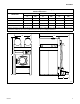
Installation Mechanical Installation Refer to Figure 1 for a typical installation of individual mounting bolts for the water saving frame. Mounting Bolt Installation for Cabinet Freestanding Models (UFPV) with Water Saving System 1 Refer to the Installation/Maintenance manual (P/N F232059) for mounting bolt installation information for UFPV models. 3 2 Mounting Bolt Installation for Pocket Hardmount Models (UWPV) with Water Saving System NOTE: The WSS frame must be permanently attached to the floor.
Installation UW60PV 9/16" (14 mm) 41-5/16" (1049 mm) 34-1/8" (867 mm) 3/4" 3/4" (19 mm) (19 mm) 4-13/16" (106 mm) 9/16" (14 mm) Outline of Stand Leg 2-9/16" (65 mm) 34-19/32" 2-9/16" (879 mm) (65 mm) 37-7/8" (962 mm) Outline of Stand Boundary Outline of Frame Base 39-1/4" (997 mm) 1-1/4" (32 mm) 1-1/4" (32 mm) 34-19/32" (879 mm) 2" (51 mm) 3-13/16" (97 mm) Front Edge of Machine 3-13/16" (97 mm) 4-27/32" (123 mm) 2" (51 mm) 2" (51 mm) 31-5/8" (803 mm) 35-5/8" (905 mm) 9" (229 mm) 36" (914 mm)
Installation Refer to the Water Saving System (WSS) General Specifications in this section to determine if there is adequate clearance through the door for the machine. If there is not and the WSS needs to be removed, refer to the section “Removing the Top Section”. If clearance is sufficient, proceed as follows: Removing Top Section NOTE: Allow concrete to cure before beginning installation. IMPORTANT: Move WSS by lifting from the frame only. Never move by lifting, pulling or pushing the tanks. 1.
Installation 7. Carefully lower top section over frame sides. Insert the eight top section bolts and four frame support bar bolts. Fully tighten the corresponding nuts with the corresponding bolts. NOTE: No part of the washer-extractor and the WSS should be touching. If the machine requires elevating during bolt down then the WSS will require the same amount. 8. Level the frame top section and sides. Align with the washer-extractor. 9. Tighten mounting nuts and washers to secure frame to floor.
Installation Instructions for Installation of Pocket Hardmount Models (UWPV) with Water Saving System Tank Drain Hose Assembly 1 2 Top View Read the following instructions thoroughly before proceeding. The installer must have a comprehensive understanding of the instructions before attempting installation of the WSS. Refer to Water Saving Tank Frame Foundation section for frame boltdown.
Installation 2. Installing the pump assembly (refer to Figure 5): NOTE: The pump assembly is packaged inside washer-extractor basket. a. Remove the pump assembly from packaging and place at the rear of the washer-extractor resting flat on floor. b. Route the two pump motor cable connections to the WSS control housing (Figure 8). Slide cable connectors in and twist to lock. Pump cables and receptacles are marked “PA” and “PB”. Refer to Figure 7. c.
Installation 4 3 2 1 2 6 5 7 11 8 20 18 19 8 8 10 9 17 10 9 11 12 16 21 13 14 Side View 15 Rear View Q039I 1 2 3 4 5 6 7 8 9 10 Large Hose Clamp Tank Elbow 2" Tank Overflow Vacuum Vent Small Hose Clamp Left Tank Right Tank Frame Side Pump Hoses Pump Assembly 11 12 13 14 15 16 17 18 19 20 Ball Valve Pump Fan End Top Pump Bottom Pump Counterclockwise Pump Rotation Carriage Bolts to Skid Frame Side Legs Tank Drain Hose Assembly To Washer-Extractor Shell Pipe (Not Shown) Frame Figure 5
Installation UW Integrated Water Saving System Machine Orientation 1 4 2 6 5 3 Q043I 1 2 3 4 5 6 Washer-Extractor Control Module Water Saving Control Housing Quick Connect Receptacle for Tank “A” Pump Motor Quick Connect Receptacle and Plug, C2 (Power) Quick Connect Receptacle for Tank “B” Pump Motor Quick Connect Receptacle and Plug, C1 (Signal) Figure 6 16 F232122
;; ; ; Installation 1 GENERALIZED SKETCH OF ELECTRICAL CONNECTIONS WATER SAVER SYSTEM (220V) REFER TO INSTRUCTIONS AND DRAWING #634148 FOR DETAILS 2 ; ; 3 4 5 6 7 Q041I 1 2 3 4 5 6 7 Remote Mounted Control Module for Water Saving System Rear of Control Module on Host Machine C1 (Signal) Quick Connect Receptacle and Plug Cable 133 to Tank “A” Drain Valve Cable 132 to Tank “B” Drain Valve Pumps “A” and “B” Quick Connect Receptacle and Plug C2 (Power) Quick Connect Receptacle and Plug Figure 7 F23
Installation Tank Overflows Steam Heat Option Some tank overflows have external 2" PVC connections. These connections may be plumbed to an open trough or floor drain. CAUTION Tank damage. Connections made to the overflow must point downward from the tank. Routing plumbing upward will damage tanks. IMPORTANT: Connections made to the overflow must provide adequate support for weight of pipe and fittings. 18 WARNING Hot Surfaces. Will cause severe burns.
Installation Instructions for Installation of Cabinet Freestanding Models (UFPV) with Water Saving System 1. Removing the water tanks (if necessary): a. Remove the three cap plugs located near the rear and one located near the front on each side of the tanks. Refer to Figure 8. Read the following instructions thoroughly before proceeding. The installer must have a comprehensive understanding of the instructions before attempting installation of the WSS. b.
Installation rear of the washer-extractor to the right of the pump assembly. Refer to Figure 9. e. Remove the four bolts from each tank located behind cap plug at each corner. Refer to Figure 9. b. Unscrew the two pump motor electrical quick disconnects from the water saving control housing located at the rear of the washerextractor. f. Lift tanks off the washer-extractor. CAUTION c. Slide off the long black hoses that run from the water tanks. Refer to Figure 9.
Installation 4. Reassembling the pump assembly: a. Replace pump assembly at the rear of the washer-extractor, resting flat on the floor. b. Secure the two pump motor electrical quick disconnects to the water saving control housing. c. Replace manifold hose clamp at rear of washer-extractor. d. Check ball valve for closed position. Before operating machine, ball valve must be closed.
Notes 22 F232122
Maintenance Daily Weekly Beginning of Day Clean tanks by removing cap on top of tanks and flush out with a hose. Sanitize as needed. Inspect water saving tanks and all associated plumbing connections for leaks. End of Day Run drain tank cycle. Monthly Flush drain ball valve, opening fully, to purge any lint or debris from pump manifold. Check top section nuts on tank frame to ensure they are tightened to the specified torque (220 in. lb.).
Notes 24 F232122
Removal from Service Decommissioning Check water tanks to make sure all water has been emptied from both tanks.
Notes 26 F232122
Operation LED Display Manual Mode Control Feature The following table lists the various displays for the Water Saving System (WSS) and what they mean. WSS functions are not manually controllable. These displays are the same for both models and are displayed in the left two display digits. The operator should become familiar with these computer displays.
Notes 28 F232122
Programming NOTE: The following programming information is for both Cabinet Freestanding and Pocket Hardmount models with the Water Saving System (WSS). Use in conjunction with respective operating/programming manuals. When programming steps using the WSS, the computer must be in the PROGRAM mode and ready for the next step. The display will read “nncc”, where “nn” represents step number and “cc” represents cycle number. Programming a Recovery Fill from Water Saving Tank(s) 1. Press the Auxiliary key.
Suplemento Sistema de ahorro de agua Suplemento de instrucciones de instalación, mantenimiento, operación y programación Refiérase a la identificación de modelos en la pagina 35 UW UF Q027I Q027IE3A Guarde estas instrucciones para referencia futura. (Si esta máquina cambia de dueño, este manual deberá ser entregado con la misma). Pieza No.
Contenido Introducción ........................................................................................ 35 Identificación de modelos..................................................................... 35 Instalación ........................................................................................... Espacios libres ...................................................................................... Cimientos para la máquina .................................................................
Notas 34 F232122 (SP)
Introducción Identificación de modelos La información contenida en este manual es aplicable a los siguientes modelos: UW 60 PV UW 100 PV UF 35 PV UF 50 PV UF 85 PV F232122 (SP) 35
Notas 36 F232122 (SP)
Instalación Este manual debe usarse junto con la información que aparece en los manuales con números de parte F232084, F232089, F232058 y F232059 (que se suministran con la lavadora extractora). Este manual está diseñado como un suplemento para la instalación, mantenimiento, operación y programación de las lavadoras extractoras modelos PV de gabinete autoestable y cilíndrica de montaje permanente, equipadas con el sistema de ahorro de agua (WSS).
Instalación Espacios libres UWPV cilíndrica de montaje permanente con sistema de ahorro de agua Dimensiones de la máquina* 60 100 Dimensiones plg mm plg mm A 41-7/16 1052,5 47-1/16 1195,4 B 91 2311 95-5/8 2428,9 C 61-3/4 1568 73-1/4 1861 D 15-3/4 400 15-3/4 400 * Deje una separación de por lo menos 610 mm (24 plg) por la parte trasera y 460 mm (18 plg) por los lados, para fines de mantenimiento, inspección y ajuste.
Instalación UFPV de gabinete autoajustable con sistema de ahorro de agua Dimensiones de la máquina* 35 50 85 Dimensiones mm plg mm plg mm plg A 889 35 990,6 39 1181,1 46-1/2 B 2070 81-1/2 2159 85 2426 95-1/2 C 1448 57 1537 60-1/2 1727 68 D 400 15-3/4 400 15-3/4 400 15-3/4 * Deje una separación de por lo menos 610 mm (24 plg) por la parte trasera y 460 mm (18 plg) por los lados, para fines de mantenimiento, inspección y ajuste.
Instalación Cimientos para la máquina Para obtener la información relacionada con los cimientos, tanto para el modelo UWPV como para el modelo UFPV, consulte la sección correspondiente de los manuales de instalación/mantenimiento respectivos. Para obtener la información sobre los modelos UFPV con el sistema de ahorro de agua, consulte en la Tabla 1 los datos de carga total sobre el piso.
Instalación Instalación mecánica Instalación de pernos de montaje para modelos de lavadora extractora de gabinete autoestable (UFPV) con sistema de ahorro de agua En la Figura 1 se indica la instalación típica de los pernos de montaje individuales en la estructura del sistema de ahorro de agua. 1 Consulte el manual de instalación/mantenimiento (N/P F232059) para obtener información sobre la instalación de los pernos de montaje en los modelos UFPV.
Instalación plg 1049 mm (41-5/16 plg) UW60PV 14 mm (9/16 plg) 867 mm (34-1/8 plg) 19 mm (3/4plg) 106 mm (4-13/16 plg) 19 mm (3/4 plg) 14 mm (9/16 plg) Perfil de la pata de soporte 65 mm (2-9/16 plg) 879 mm (34-19/32 plg) 65 mm (2-9/16 plg) 962 mm (37-7/8 plg) Perfil del área ocupada por la unidad 997 mm (39-1/4 plg) 32 mm (1-1/4 plg) Perfil de la base de la estructura 879 mm (34-19/32 plg) 51 mm (2 plg) 97 mm (3-13/16 plg) 123 mm (4-27/32 plg) 32 mm (1-1/4 plg) 97 mm (3-13/16 plg) Borde d
Instalación Consulte en esta sección las especificaciones generales del sistema de ahorro de agua (WSS) para determinar si hay una separación adecuada alrededor de la puerta de la máquina. Si no la hay, y el WSS necesita ser retirado, consulte la sección “Desmontaje de la sección superior”. Si la separación es suficiente, continúe como se indica a continuación: NOTA: Espere a que el concreto (hormigón) se cure antes de comenzar la instalación. 1. Coloque el WSS al lado del cimiento de concreto.
Instalación 7. Baje con cuidado la sección superior sobre los lados de la estructura. Inserte los ocho pernos de la sección superior, y los cuatro pernos de la barra de soporte de la estructura. Coloque las tuercas correspondientes y apriételas bien. NOTA: La lavadora extractora y el WSS no deben hacer contacto en ningún punto. Si es necesario elevar la máquina para apretar los pernos, el WSS deberá elevarse también a una altura equivalente. 8. Nivele la sección superior y los lados de la estructura.
Instalación Instrucciones para instalación de modelos de lavadora extractora cilíndrica de montaje permanente (UWPV) con sistema de ahorro de agua Montaje de manguera de desagüe de los tanques 1 2 Vista superior Lea detenidamente las instrucciones siguientes antes de proceder. El instalador deberá estar bien familiarizado con las instrucciones antes de intentar la instalación del WSS.
Instalación 2. Instalación del conjunto de bombas (consulte la Figura 5): 3. Instalación de la manguera de la bomba y las bocas de ventilación: NOTA: El conjunto de bombas viene en un paquete dentro del cesto de la lavadora extractora. NOTA: Las mangueras de bomba y las bocas de ventilación vienen en un paquete dentro del cesto de la lavadora extractora. a.
Instalación 4 3 2 1 2 6 5 7 11 8 20 18 19 8 8 10 9 17 10 9 11 12 16 21 13 14 Vista Lateral 15 Vista Posterior Q039I 1 2 3 4 5 6 7 8 9 10 11 12 Abrazadera de manguera larga Codo de tanque Agujero de desagüe de tanque de 2 plg Agujeros de ventilación de vacío Abrazadera de manguera pequeña Tanque izquierdo Tanque derecho Lados de la estructura Mangueras de bomba Conjunto de bombas Válvula de bola Extremo de ventilador de bomba 13 14 15 16 17 18 19 20 Bomba superior Bomba inferior Rotaci
Instalación Orientación de la máquina con sistema de ahorro de agua integrado UW 1 4 2 6 5 3 Q043I 1 2 3 4 5 6 Módulo de control de la lavadora extractora Alojamiento del control de ahorro de agua Receptáculo de conexión rápida para el motor de la bomba del Tanque “A” Receptáculo y clavija de conexión rápida, C2 (Alimentación) Receptáculo de conexión rápida para el motor de la bomba del Tanque “B” Receptáculo y clavija de conexión rápida, C1 (Señal) Figura 6 48 F232122 (SP)
;; ; ; Instalación 1 ILUSTRACION GENERALIZADA DE CONEXIONES ELECTRICAS DEL SISTEMA DE AHORRO DE AGUA (220V). CONSULTE LAS INSTRUCCIONES Y LA GRAFICA #634148 PARA MAYORES DETALLES.
Instalación Agujeros de rebose de los tanques Algunos agujeros de rebose tienen conexiones externas de PVC de 2 plg. Estas conexiones pueden desaguarse en una batea o desagüe en el piso. PRECAUCIÓN Daño al tanque. Las conexiones hechas a la salida de desborde deberán apuntar hacia abajo del tanque. El tendido de tubería hacia arriba causará daño a los tanques.
Instalación Instrucciones para instalación de modelos de lavadora extractora de gabinete autoestable (UFPV) con sistema de ahorro de agua a. Saque los tres tapones de sombrerete (dos de ellos ubicados cerca de la parte posterior, y el otro ubicado cerca de la parte frontal), por cada lado de los tanques. Consulte la Figura 8. Lea detenidamente las instrucciones siguientes antes de proceder. El instalador deberá estar bien familiarizado con las instrucciones antes de intentar la instalación del WSS. b.
Instalación b. Desenrosque del alojamiento de control del sistema de ahorro de agua (localizado en la parte posterior de la lavadora extractora) las dos piezas de desconexión eléctrica rápida de los motores de bomba. e. Saque los cuatro pernos de cada tanque, localizados detrás del tapón de sombrerete en cada esquina. Consulte la Figura 9. f. Levante los tanques de la lavadora extractora. c. Saque las dos mangueras negras largas conectadas a los tanques de agua. Consulte la Figura 9.
Instalación 4. Montaje del conjunto de bombas: a. Reinstale el conjunto de bombas en la parte posterior de la lavadora extractora, en posición horizontal sobre el piso. b. Asegure las dos piezas de conexión eléctrica de los motores de bomba al alojamiento del control del sistema de ahorro de agua. c. Coloque la abrazadera de la manguera del distribuidor en la parte posterior de la lavadora extractora. d. Compruebe que la válvula de bola está en la posición cerrada.
Notas 54 F232122 (SP)
Mantenimiento Diariamente Mensualmente Al comienzo del día Enjuague con abundante agua la válvula de bola de desagüe; para ello, ábrala completamente a fin de purgar todas las pelusas y partículas que haya en el distribuidor de bombas. Inspeccione que no haya fugas en los tanques del sistema de ahorro de agua ni en ninguna de las conexiones asociadas con los mismos. Al final del día Active el ciclo de desagüe de los tanques.
Notas 56 F232122 (SP)
Puesta fuera de servicio Puesta fuera de servicio Asegúrese de que se ha vaciado toda el agua de los tanques.
Notas 58 F232122 (SP)
Operación Pantalla de LED Función de control del modo manual En la siguiente tabla se presentan las diferentes pantallas correspondientes al sistema de ahorro de agua (WSS) y lo que éstas significan. No resulta posible el regular con la mano las funciones del WSS (sistema de ahorro de agua). Estas pantallas son iguales para ambos modelos, y aparecen en los dos dígitos izquierdos de la pantalla. Es conveniente que el operador se familiarice con estas pantallas.
Notas 60 F232122 (SP)
Programación NOTA: La siguiente información de programación se aplica a los modelos de gabinete autoestable y a los modelos cilíndricos de montaje permanente de lavadoras extractoras con sistema de ahorro de agua (WSS). Emplee esta información junto con la incluida en los respectivos manuales de operación/ programación. Cuando programe pasos en los que intervenga el WSS, el ordenador deberá estar en el modo de programa (PROGRAM) y listo para el paso siguiente.
Notas 62 F232122 (SP)