
Specifications
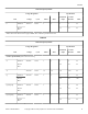


Supply Dispensing
Capacities 20–100 125
Number of liquid
chemical supply
signals [OPL on-
ly]
4 4
Number of sup-
ply compart-
ments
4 0 or 5 [optional]
Number of exter-
nal liquid supply
connections
5 5
Liquid supply
connection size
3/8 in. [8 mm] 5/8 in. [15.9 mm]
Table 42
IMPORTANT: Undiluted chemical dripping can damage
the machine. All chemical injection supply dispenser
pumps and dispenser tubing should be mounted below
the washer’s injection point. Loops do not prevent
drips if these instructions are not followed.
IMPORTANT: Failure to follow these instructions could
damage the machine and void the warranty.
External Supplies
For proper communication between the machine and an external
chemical supply system, it is important for the low-voltage signal
power to be connected properly. The included wiring diagram
shows several different options for safe and correct wiring of this
interface.
The preferred method for connecting the wiring from the external
chemical supply system to the machine is to use the 300mA pow-
er of the machine’s 24VAC control transformer, which is inten-
ded strictly for this purpose. Other voltage and current options
are available, but require some wiring changes and must be pro-
vided with an external power source. Under no circumstances
should the high-voltage machine supply connections or source be
used for the communication wiring.
Communication wiring connections, which include a single row
of identified terminal blocks, can be found under a service panel
at the upper back of the machine.
Chemical Injection Using Internal 24VAC Control
Transformer
NOTE: Using the Internal 24VAC 300 Milliamp Control
Transformer is recommended by Alliance Laundry Sys-
tems.
CAUTION
Do not attempt to increase fuse rating or alter wiring
of external chemical supply terminal strip in such as
way that may conflict with the suggested methods
provided on the Optional External Supply Wiring Di-
agram.
W699
IMPORTANT: DO NOT remove the red jumper wire from
the terminal strip.
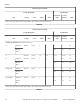
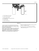
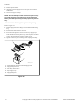
EXTERNAL DISPENSER CONNECTIONS
RELAY COM
RELAY
COM
Supply 1
External
Dispensing
System
Internal
Supply
300mA Max
24VAC COM
24VAC COM
JUMPER FOR INTERNAL
24 VAC SUPPLY
CONNECTED TO RELAY
COM. (REMOVE IF NOT
WIRING TO INTERNAL
24 VAC SUPPLY
STEP 1: Insert screwdriver & press down
to open cage clamp.
STEP 2: Insert Wire
8.5mm
Strip Length
Wire Size 28-16AWG
0.08-1.5mm
24VAC
RED
ES 1
ES 2
ES 3
ES 4
EXAMPLE FOR EXTERNAL
DISPENSER CONNECTION
CHM2336N_SVG
4
3
2
1
1. Relay Com
2. Red Jumper Wire
3. 24 VAC
4. Transformer
Figure 32
There are 3 terminals necessary for this connection option.
• Terminal “24VAC COM” is used to connect one side of the
internal control transformer to the external dispenser input
signals common.
• The second terminal is used to connect the other side of the
control transformer to the machine output signals common
through a red jumper wire between “24VAC” and “RELAY
COM”. Refer to Figure 33 .
IMPORTANT: Do not use the transformer terminals if
an external power supply is used.
Installation
66
©
Copyright, Alliance Laundry Systems LLC - DO NOT COPY or TRANSMIT Part No. F8429301ENR13