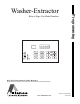
Programming Washer-Extractor Refer to Page 4 for Model Numbers CHM537R CHM Keep These Instructions for Future Reference. (If this machine changes ownership, this manual must accompany machine.) www.comlaundry.com Part No.
WARNING Failure to install, maintain, and/or operate this machine according to the manufacturer's instructions may result in conditions which can produce bodily injury and/or property damage. W030 F8238101 NOTE: The WARNING and IMPORTANT instructions appearing in this manual are not meant to cover all possible conditions and situations that may occur. It must be understood that common sense, caution, and carefulness are factors which cannot be built into these machines.
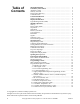
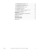
Table of Contents Model Identification ........................................................................... Preliminary Information.................................................................... About the Control ................................................................................. Glossary of Terms................................................................................. Power Failure Recovery .......................................................................
14. Manual Rapid Advance (On/Off) “rAEn” ................................... 15. No Cycle Time Display “nCtd” ................................................... 16. Programmable Cycle Time Display “PCtd” ................................ 17. Slow Drain Detection Adjust “SdAd” ......................................... 18. Set Real-Time Clock “rtC-”’ ....................................................... 19. Manual Diagnostics (On/Off) “dAEn” ........................................ 20.
Model Identification Information in this manual is applicable to these machine models: 4 SCL030KN2 SCN125KNV UCL080KNV SCL030KNF SCU020KN2 UCL125KNV SCL030KNV SCU020KNF UCN020KN2 SCL040KN2 SCU030KN2 UCN030KN2 SCL040KNF SCU030KNF UCN030KNF SCL040KNV SCU040KN2 UCN040KN2 SCL060KN2 SCU040KNF UCN040KNF SCL060KNV SCU040KNV UCN040KNV SCL080KNV SCU060KN2 UCN060KN2 SCL125KNV SCU060KNF UCN060KNF SCN020KN2 SCU060KNV UCN060KNV SCN020KNF SCU080KNV UCN080KNV SCN030KN2 SCU125KNV UCU
Preliminary Information About the Control Power Failure Recovery This control is an advanced, programmable computer that lets the owner control most machine features by pressing a sequence of keypads. Refer to Figure 1. If a cycle is in progress and the power fails for less than five seconds, the cycle status is saved in memory. When the power recovers, the machine will resume into the previously active cycle.
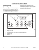
Control Identification Select Cycle Pads (Refer to Figure 1) SELECT CYCLE pads are used to select the specific washer cycle. These pads are numbered 0-9 and allow the user to select a cycle other than the default cycle (#5). The SELECT CYCLE keypads are not active after starting a cycle. Pressing the flashing START pad will confirm the selection and the cycle will begin.
Display Identification Light Emitting Diodes (LEDs) (Refer to Figure 1) LIGHT EMITTING DIODES (LEDs) are used to indicate the chosen cycle, cycle status, when the bleach compartment is dispensing, and door lock information. See below for information on each LED. WASH LED Wash LED is lit at the beginning of a wash portion of the cycle and will remain lit until the wash is complete. RINSE LED Rinse LED is lit at the beginning of a rinse portion of the cycle and will remain lit until the rinse is complete.
Machine Operation Start Up Run Mode When power is applied to the machine, the control will display its software version as “S xx” (“xx” is the version number) for one second. If the control was not powered down during a running cycle, it will enter Start Mode. The control enters this mode when a cycle is running. The time remaining appears in the display, the status LED’s are lit and the loading door is locked.
Special Features Programming Control The control allows the machine owner to program the control with the use of the keypad. Cycle options may be programmed, audit information may be viewed and diagnostic tests may be run by pressing combinations of the SELECT CYCLE keypads. For details on programming select cycle options, refer to Programming Control.
Opening the Top Cover To manually program the control, the top cover must be opened. Opening and closing the top cover trips a switch which allows access to various programming options. Once opened, the top cover may either be left open, and then closed after programming, or it may be closed immediately. The top cover is located on the top of the machine. 1. Unlock top cover. 2. Slide top cover forward slightly to move notches away from the pegs on the front of the cabinet. 3. Lift the top cover up.
Entering the Manual Mode For programming, testing, and retrieving information from the control, it is often necessary to enter the Manual Mode by following the six simple steps below. How to Enter the Manual Mode 1. If the washer is in an active cycle, rapid advance through the cycle. Refer to the Rapid Advance Feature. Manual Programming Manual Programming (Prog) Manual Read Audit (AUdt) Manual Reset (rSEt) Manual Rapid Advance Rapid Advance (rAPd) 2. Open the top cover. Refer to Opening the Top Cover.
Programming Control What Can Be Programmed? This feature allows the owner to program cycle information and other features by using the keypads. The control must have the Manual Programming Mode enabled, which is the factory default. This mode can only be turned “oFF” and “on” by using an external device. Refer to this section when programming the control. This section offers a detailed description of all available programmable options.
Programming Control Table 1 (continued) Option Number 2. Option Display Description Default Value Value Range - - ** on/oFF "FILL" Fill Step a.) "FLEn" Fill Step Enable/Disable b.) "FLEU" Fill Level ** HI/nEd/Lo or 1 - 30 c.) "tEnP" Fill Temperature ** CoLd/Uarn/Hot or 35°F - 194°F/2°C - 90°C - - 3. "SUPL" Supply Step a.) "SUEn" Supply Step Enable/Disable ** on/oFF b.
Programming Control Table 1 (continued) Option Number c.) Option Display "HEAt" Heat in Agitate (if heater is present) 5. "drAn" Drain Step 6. c. Description "SPIn" Spin Step a.) "SPEn" Extract Step Enable/Disable b.) "SSEC" Extract Seconds Default Value Value Range ** oFF/1/2** - on/oFF - - ** on/oFF ** 0 - 59 c.) "SnIn" Extract Minutes ** Intermediate Extract: Min. Step Time = 30 seconds, Max. Step Time = 3:59 minutes d.
Programming Control Table 1 (continued) Option Number Option Display Description Default Value Value Range 27 21 - 30 22 "FHI" High Water Level 23 "tCF" Temperature Controlled Fill oFF on/oFF 24 "ALd-" Auto-Water Leak Detection - - a. "ALd1" Auto-Water Leak Detection (On/Off and cycles) oFF oFF/0 - 127 (Cycles) b. "ALd2" Auto-Water Leak Detection Hour 0 0 - 23 c. "ALd3" Auto-Water Leak Detection Day of Week 127* 0 - 127* *Refer to programming section for value definition.
Programming Control Manual Mode Flowchart Enter Manual Mode. 1. Open top cover 2. Press and hold both #4 keypad and #1 keypad at the same time. “rAPd” - Quickly advance through active cycles. 1. Press START (enter) keypad to begin Rapid Advance cycle and advance through cycle steps. “Prog” - Program cycle information and other features into the Control. 1. Refer to the Manual Programming flowchart. “AUdt” - Retrieve audit information for machine. 1. Press START (enter) keypad.
Programming Control Manual Programming Flowchart (1 of 3) “dCYC” - Set the default cycle and temperature “Aud” - Program when the signal will sound “E FL” - Fill Error “E dr” - Drain Error “E Ub” - Unbalance Error (VFD only) “E oP” - Open Thermistor Error (Models with Heat) “Err” - Turn on/off certain errors in control “E SH” - Shorted Thermistor Error (Models with Heat) “LEr1” - Water Leak Detection during a Machine Cycle “E Ht” - Heat Error (Heater only) “LEr2” - Water Leak Detection Day of Week “
Programming Control Manual Programming Flowchart (2 of 3) (continued) (continued) (continued) “SUEn” - Supply Step Enable/Disable: “on” = Enable “oFF” = Disable “C2” or “S1” Compartment #2/ Supply #1: “on” = Enabled “oFF” = Disabled (Design 1 Models) “dISP” - Dispenser Options: Press START (enter) to access options “C3” or “S2” Compartment #3/ Supply #1: “on” = Enabled “oFF” = Disabled (Design 1 Models) “C3” Compartment #3 “on” = Enabled “oFF” = Disabled (Design 2 Models) “C4” or “S3” Compartment #
Programming Control Manual Programming Flowchart (3 of 3) (continued) “SUPC” (Design 1 models only) Choose either supply dispenser or compartment dispenser. Dispenser: “S” = Supply Dispenser “C” = Compartment Dispenser “bALr” (VFD only) - Program the number of times control will retry balancing the load before moving to extract step: 1-7.
Programming Control Diagnostic Tests Flowchart “dIAg” - Diagnostic Tests. 1. Press START (enter) keypad.
Programming Control “dIAg” - Diagnostic Tests. 1. Press START (enter) keypad.
Programming Control This option allows the owner to set the default cycle the machine will enter when in the Start Mode. How to Program Default Cycle 1. Control must be in Manual Mode. Refer to Entering the Manual Mode. < > 2. Press the #3 ( ) or the #6 ( ) keypad until “Prog” appears in the display. Press the START (enter) keypad and “dCYC” will appear in the display. 3. When “dCYC” appears in the display, press the START (enter) keypad. A number will appear in the display.
Programming Control 2. Audio Signal “AUd” How to Program the Audio Signal There are two occasions when a signal may sound during operation. These two occasions are listed below: 2. Press the #3 ( ) or the #6 ( ) keypad until “Prog” appears in the display. Press the START (enter) keypad and “dCYC” will appear in the display. < 1. Control must be in Manual Mode. Refer to Entering the Manual Mode. > This option allows the owner to program when the signal will sound. 2.
Programming Control How to Read Table 2 To determine the correct number required to program the Audio Signal, use the following chart. The Signal Value column contains the number required in step 6. The other columns correspond to individual options. Each column of options contains a unique combination of the words “ON” and “OFF” that indicates if that column’s option is turned on or off when the Signal Value is entered.
Programming Control 3. Error Code Programming “Err-” This option allows the owner to turn on or turn off certain errors in the control. How to Program Error Code Programming 1. Control must be in Manual Mode. Refer to Entering the Manual Mode. < > 2. Press the #3 ( ) or the #6 ( ) keypad until “Prog” appears in the display. Press the START (enter) keypad and “dCYC” will appear in the display.
Programming Control Day(s) of the Week Enabled Values Day Of Week Value SAT FRI THUR WED TUE MON SUN 0 OFF OFF OFF OFF OFF OFF OFF 1 OFF OFF OFF OFF OFF OFF ON 2 OFF OFF OFF OFF OFF ON OFF 3 OFF OFF OFF OFF OFF ON ON 4 OFF OFF OFF OFF ON OFF OFF 5 OFF OFF OFF OFF ON OFF ON 6 OFF OFF OFF OFF ON ON OFF 7 OFF OFF OFF OFF ON ON ON 8 OFF OFF OFF ON OFF OFF OFF 9 OFF OFF OFF ON OFF OFF ON 10 OFF OFF OFF ON OFF ON OFF 1
Programming Control Table 4 (continued) Day(s) of the Week Enabled Values Day Of Week Value 41 42 43 44 45 46 47 48 49 50 51 52 53 54 55 56 57 58 59 60 61 62 63 64 65 66 67 68 69 70 71 72 73 74 75 76 77 78 79 80 81 82 83 84 SAT FRI THUR WED TUE MON SUN OFF OFF OFF OFF OFF OFF OFF OFF OFF OFF OFF OFF OFF OFF OFF OFF OFF OFF OFF OFF OFF OFF OFF ON ON ON ON ON ON ON ON ON ON ON ON ON ON ON ON ON ON ON ON ON ON ON ON ON ON ON ON ON ON ON ON ON ON ON ON ON ON ON ON ON ON ON ON OFF OFF OFF OFF OFF OFF OF
Programming Control Table 4 (continued) Day(s) of the Week Enabled Values Day Of Week Value 85 86 87 88 89 90 91 92 93 94 95 96 97 98 99 100 101 102 103 104 105 106 107 108 109 110 111 112 113 114 115 116 117 118 119 120 121 122 123 124 125 126 127* SAT FRI THUR WED TUE MON SUN ON ON ON ON ON ON ON ON ON ON ON ON ON ON ON ON ON ON ON ON ON ON ON ON ON ON ON ON ON ON ON ON ON ON ON ON ON ON ON ON ON ON ON OFF OFF OFF OFF OFF OFF OFF OFF OFF OFF OFF ON ON ON ON ON ON ON ON ON ON ON ON ON ON ON ON ON
Programming Control 1. Control must be in Manual Mode. Refer to Entering the Manual Mode. < > 2. Press the #3 ( ) or the #6 ( ) keypad until “Prog” appears in the display. Press the START (enter) keypad and “dCYC” will appear in the display. < > 3. Press the #3 ( ) or the #6 ( ) keypad to scroll through the programmable options until “Cy--” appears in the display. Press the START (enter) keypad and “Cy01” will appear in the display. < > 4.
Programming Control NOTE: If the Segment Enable/Disable is programmed “oFF”, the other Cycle Segment programming options can’t be accessed. 4. Press the START (enter) keypad when the desired Cycle Segment programmable option appears in the display. Programming Segment Enable/Disable 1. When “SgEn” appears in the display, press the START (enter) keypad. The current Segment Enable/Disable status will appear in the display. “on” = Segment Enabled “oFF” = Segment Disabled < > 2.
Programming Control < > 2. Press the #3 ( ) or the #6 ( ) keypad to scroll through the programmable Supply step options. Refer to Table 7. NOTE: Supply Step “SUEn” must be enabled to scroll through all Supply Step options. 3. Press the START (enter) keypad when the desired option appears in the display. The current status value will appear in the display. Refer to Table 7.
Programming Control Programming Agitate Step Programming Drain Step 2. Press the #3 ( ) or the #6 ( ) keypad to scroll through the programmable Agitate step options. Refer to Table 8. 2. Press the #3 ( ) or the #6 ( ) keypad to change the current status.
Programming Control M Extract Description Step “on”/“oFF” “SSEC” Extract Seconds “0” - “59” “SnIn” Extract Minutes This option allows the owner to program minutes to the cycle’s display time. 1. Press the #3 ( ) or the #6 ( ) keypad to scroll through the programmable Cycle Programming options until “Cnin” appears in the display.
Programming Control < > 2. Press the #3 ( ) or the #6 ( ) keypad until “Prog” appears in the display. Press the START (enter) keypad, and “dCYC” will appear in the display. < > 3. Press the #3 ( ) or the #6 ( ) keypad to scroll through the programmable options until “SUPC” appears in the display. 4. When “SUPC” appears in the display, press the START (enter) keypad. The current dispenser option will appear in the display. “S” = Supply Dispenser “C” = Compartment Dispenser (Default Setting) < > 5.
Programming Control 7. IR Access (On/Off) “IrA” 8. Fahrenheit/Celsius “t FC” This option allows the owner to enable or disable allowing the control to be read by an external device. This option allows the owner to set whether the display will be shown in Fahrenheit or Celsius. How to Program the IR Access (On/Off) How to Program Fahrenheit/Celsius 3. Press the #3 ( ) or the #6 ( ) keypad to scroll through the programmable options until “IrA” appears in the display. 3.
Programming Control Hot Water Temperature “FH” This option allows the owner to program the hot water temperature for models equipped with heat. How to Program Hot Water Temperature 4. When “FH” appears in the display, press the START (enter) keypad. A number will appear in the display. This number corresponds to the current Hot Water Temperature value. < 5. Press the #3 ( ) or the #6 ( ) keypad to increase or decrease the current Hot Water Temperature value to the desired Hot Water Temperature value.
Programming Control < < > 3. Press the #3 ( ) or the #6 ( ) keypad to scroll through the programmable options until “FC” appears in the display. 4. When “FC” appears in the display, press the START (enter) keypad. A number will appear in the display. This number corresponds to the current Cold Water Temperature value. < > 5. Press the #3 ( ) or the #6 ( ) keypad to increase or decrease the current Cold Water Temperature value to the desired Cold Water Temperature value. 1.
Programming Control 13. Production Test Cycle (On/Off) “PtEn” 14. Manual Rapid Advance (On/Off) “rAEn” This option allows the owner to enable or disable access to the production test cycle. Refer to Production Test Cycle section for more information. This option allows the owner to enable or disable the rapid advance feature. Refer to Rapid Advance Feature section for more information. How to Program the Production Test Cycle (On/Off) How to Program the Manual Rapid Advance (On/Off) 3.
Programming Control < > 3. Press the #3 ( ) or the #6 ( ) keypad to scroll through the programmable options until “nCtd” appears in the display. 4. When “nCtd” appears in the display, press the START (enter) keypad. The current No Cycle Time Display status will appear in the display. “on” = Option Enabled “oFF” = Option Disabled (Default Setting) < > 5. Press the #3 ( ) or the #6 ( ) keypad to change the current status. 6. Press the START (enter) keypad when the desired status appears in the display.
Programming Control This option allows the owner to increase or decrease the slow drain detection threshold by adding additional seconds to the threshold value. When enabled, it increases the time before a Slow Drain Error will occur. 5. Press the #3 ( ) or the #6 ( ) keypad to change the current value. How to Program the Pause/Resume Mode(On/Off) 1. Control must be in Manual Mode. Refer to Entering the Manual Mode. < > 2. Press the #3 ( ) or the #6 ( ) keypad until “Prog” appears in the display.
Programming Control How to Program the Time and Date 1. Control must be in Manual Mode. Refer to Entering the Manual Mode. < > 2. Press the #3 ( ) or the #6 ( ) keypad until “Prog” appears in the display. Press the START (enter) keypad and “dCYC” will appear in the display. < > 3. Press the #3 ( ) or the #6 ( ) keypad to scroll through the programmable options until “rtC-” appears in the display. Press the START keypad and “rtC1” will appear in the display. < > 4.
Programming Control < > 3. Press the #3 ( ) or the #6 ( ) keypad to scroll through the programmable options until “dAEn” appears in the display. 4. When “dAEn” appears in the display, press the START (enter) keypad. The current Manual Diagnostics status will appear in the display. “on” = Option Enabled (Default Setting) “oFF” = Option Disabled < > 5. Press the #3 ( ) or the #6 ( ) keypad to change the current status. 6. Press the START (enter) keypad when the desired status appears in the display.
Programming Control 21. Medium Water Level “FnEd” 22. High Water Level “FHI” This option allows the owner to program the medium water level during fill and tumble of all cycles. This option allows the owner to program the high water level during fill and tumble of all cycles. How to Program Medium Water Level How to Program High Water Level 3. Press the #3 ( ) or the #6 ( ) keypad to scroll through the programmable options until “FnEd” appears in the display. 3.
Programming Control This option allows the owner to enable or disable a Temperature Controlled Fill. When enabled, the control will regulate the temperature of the fill to the temperature programmed in options 9, 10 and 11. How to Program Temperature Controlled Fill 1. Control must be in Manual Mode. Refer to Entering the Manual Mode. < > 2. Press the #3 ( ) or the #6 ( ) keypad until “Prog” appears in the display. Press the START (enter) keypad and “dCYC” will appear in the display. < 5.
Programming Control This option allows the owner to set the time and frequency that the control automatically checks the water level. The owner programs which day(s) of the week and hour of day(s) they want this test to occur. The owner may also program this test to only occur after XX number of machine cycles have been completed since the last time the test was run. In order for this Auto-water Leak Detection test to occur, the machine’s door must be closed. 6.
Collecting Audit Information How to Enter Audit Feature 1. Control must be in Manual Mode to start. Refer to Entering the Manual Mode. 1. Use the #3 ( ) or the #6 ( ) keypad to scroll through various options until the desired option is shown in the display. Refer to the Audit Options List, Table 12, for an explanation of the audit options available. < > 2. Press the #3 ( ) or the #6 ( ) keypad until “AUdt” appears. How to Read Audit Data 3. Press the START (enter) keypad. “CyC” will appear.
Manual Reset This feature allows the owner to reset the machine control’s programming data to the factory default settings by pressing a sequence of pads on the control. How to Enter Manual Reset 1. Control must be in Manual Mode to start. Refer to Entering the Manual Mode. < > 2. Press the #3 ( ) or the #6 ( ) keypad until “rSEt” appears. 3. Press the START (enter) keypad. The control will be blank until the programming is complete.
Testing Machine and Electronic Control Functions Output Board Water Level Sensor Trim Value Top Cover Opening Test Door Switch Input Test Door Lock Input Test Show Fill Time Test < 2. Press the #3 ( ) or the #6 ( ) keypad until “dIAg” appears. 3. Press the START (enter) keypad. Display will change to “d001” indicating the Front End Control Software Version Number test. 4. Press the #3 ( ) or the #6 ( ) keypad to scroll through the diagnostic test options.
Testing Machine and Electronic Control Functions Diagnostic (Testing) Mode – Quick Reference Chart Test Number Diagnostic Mode Display “d001” Front End Control Software Version # Test “S xx” “d002” Output Board Control Software # Test “o xx” “d003” Output Board Water Level Sensor Trim Value “txxx” “d004” Top Cover Opening Test “A oP” or “A CL” “d009” Door Switch Input Test “drCL” or “drOP” “d010” Door Lock Input Test “drUL” or “drLO” “d011” Show Fill Time Test “Fxxx” “d012” Show Dra
Testing Machine and Electronic Control Functions Diagnostic Test Descriptions Top Cover Opening Test Front End Control Software Version Number Test This option tests the top cover switch. To start test, control must be in the Testing Mode. Refer to How to Enter Testing Feature at the beginning of this section. This option displays the front end control software version number. To start test, control must be in the Testing Mode. Refer to How to Enter Testing Feature at the beginning of this section.
Testing Machine and Electronic Control Functions Show Fill Time Test VFD Balance Input Test (Design 1 models) This test will display the average low level fill time. This average will be calculated by taking the average of the last 10 fill times from the start of the fill until the low level is reached. This option tests the VFD balance switch. To start test, control must be in the Testing Mode. Refer to How to Enter Testing Feature at the beginning of this section.
Testing Machine and Electronic Control Functions VFD Balance Weight Test (Design 1 models) Water Purge Test This test is only available on machines equipped with a variable frequency motor drive. To start test, control must be in the Testing Mode. Refer to How to Enter Testing Feature at the beginning of this section. This option empties all water from the machine. To start test, control must be in the Testing Mode. Refer to How to Enter Testing Feature at the beginning of this section.
Testing Machine and Electronic Control Functions Drive Software Version Number Test (Design 2 models only) This option displays the custom drive software version number. To start test, control must be in the Diagnostic Testing Mode. Refer to How to Enter Diagnostic Testing Feature at the beginning of this section. To enter, press the START (enter) keypad. The display will show “drxx” where “xx” is the custom drive software version number.
Testing Machine and Electronic Control Functions Production Test Cycle Quick Reference Chart Display Test Cycle Step Comments “S xx” FEC Control Software Version xx is the software version number. “o xx” Output Board Software Version xx is the software version number. “Ct 3” Control Type 3 is the control type. “oPL” Control Type OPL “USA” Control Type Domestic “drAn” or “PUnP” Drain Type Drain or Pump “tEnP” Temp Sensor Step skipped if not equipped with temp sensor.
Testing Machine and Electronic Control Functions Table 16 (continued) Production Test Cycle Quick Reference Chart Display Test Mode Comments “LoAg” Reduced Wash Speed Forward with no agitation action This step skipped on 2 Speed models. “Ag” Wash Speed Forward with no agitation action “rAg” Wash Speed Reverse with no agitation action “drAI” Drain Distribution Speed “PUrg” Factory Valve Purge “SP 1” Extract Speed #1 “very low” This step skipped on 2 Speed models.
Error Codes Following is a list of possible error codes for an electronic control. Errors beginning with “EI” refer to external device Infra-red communication errors. All other errors refer to machine errors. Display Description Cause/ Corrective Action EI01 Transmission Failure Communication failure. Re-aim external device and try again. EI02 Time-out Error Communication failure. Re-aim external device and try again.
Error Codes Table 17 (continued) Display Description Cause/ Corrective Action E dr Drain Alarm Error Machine not drained within 15 minutes (or other programmed length of time) in any drain step. End cycle. Power down machine to clear. E Ht Heat Alarm Error Programmed heat alarm time of 120 minutes or other programmed length of time is exceeded. Turns off heater output for remainder of cycle.
Error Codes Table 17 (continued) Display Description Cause/ Corrective Action Ed03** Tachometer Error The drive detects the tachometer input is damaged during power up or no tachometer signal is detected after initiating motor output. Power down, verify H3 on drive and tachometer connections on motor, power up and try again. Ed04** Locked Rotor Error Motor does not reach speed at startup. Power down, verify motor mounting and look for obstructions, power up and try again.
Rapid Advance Feature The Rapid Advance feature allows the owner to quickly advance through active cycles. How to Use Rapid Advance Control must be in an active cycle to use the Rapid Advance feature. While in the Rapid Advance Mode, pressing the START (enter) keypad will advance the machine to the next cycle step. The cycle indicator lights will tell which cycle step the machine is in. How to Exit Rapid Advance Feature 1. Advance through the cycles until reaching the Start Mode.
Communications Mode Infra-red Communications The Infra-red Communications feature allows the control to communicate with an external device. The control can be programmed and have its data read without using the keypad. It may also be used to start and stop various diagnostic tests. How to Begin Communications with An External Device The control will go blank and the display will show “-C-” until the communication is complete.
Default Cycles Perm Press Light Soil Cotton/Terry Light Soil Perm Press Medium Soil Cotton/Terry Medium Soil Perm Press Heavy Soil Cotton/Terry Heavy Soil Rags Heavy Soil CY01 CY02 CY03 CY04 CY05 CY06 CY07 Agitation type 18/3/18 Normal 18/3/18 Normal 18/3/18 Normal 18/3/18 Normal 18/3/18 Normal 18/3/18 Normal 18/3/18 Normal Wash 1 (ON/OFF) ON ON ON ON ON ON ON 7 7 2 2 2 2 2 Hot Hot Warm Warm Warm Warm Warm Cycle Stops Cycle reference (display in Program Mode) Tim
Default Cycles (continued) Cycle Stops Cycle reference (display in Program Mode) Agitation type Rinse 1 (ON/OFF) Time for agitation (min.
Default Cycles (continued) Reclaim Delicates Cold 90C 60C 40C 90C Perm Press 60C Perm Press CY08 CY09 CY10 CY11 CY12 CY13 CY14 Agitation type 18/3/18 Normal 10/20/10 Gentle 18/3/18 Normal 18/3/18 Normal 18/3/18 Normal 18/3/18 Normal 18/3/18 Normal Wash 1 (ON/OFF) ON ON ON ON ON ON ON 2 6 2 2 2 2 2 Warm Cold Warm (40°C) Warm (40°C) Warm (40°C) Warm (40°C) Warm (40°C) Cycle Stops Cycle reference (display in Program Mode) Time for agitation (min.
Default Cycles (continued) Cycle Stops Cycle reference (display in Program Mode) Agitation type Rinse 1 (ON/OFF) Time for agitation (min.
Default Cycles (continued) 40C Perm Press 70C Perm Press 50C Gentle 30C Gentle Blank CY15 CY16 CY17 CY18 CY19-CY30 Agitation type 18/3/18 Normal 18/3/18 Normal 10/20/10 Gentle 10/20/10 Gentle 18/3/18 Normal Wash 1 (ON/OFF) ON ON ON ON OFF 2 2 2 2 2 Warm (40°C) Warm (40°C) Warm (40°C) Cold Cold Fill Level Low Low Low High Low Supply C1 (S1) C1 (S1) C1 (S1) C1 (S1) OFF Cycle Stops Cycle reference (display in Program Mode) Time for agitation (min.
Default Cycles (continued) 40C Perm Press 70C Perm Press 50C Gentle 30C Gentle Blank CY15 CY16 CY17 CY18 CY19-CY30 Agitation type 18/3/18 Normal 18/3/18 Normal 10/20/10 Gentle 10/20/10 Gentle 18/3/18 Normal Rinse 1 (ON/OFF) ON ON ON ON OFF 2 2 2 2 2 Cold Cold Cold Cold Cold Cycle Stops Cycle reference (display in Program Mode) Time for agitation (min.
Default Cycles F8238101 © Copyright, Alliance Laundry Systems LLC – DO NOT COPY or TRANSMIT 67