Installation/Operation Clothes Dryer Electric and Gas Models S TION INSTRUC ING ) OPERAT (heat setting, PRESS Fabric Type PERM heat) 1. Select NORMAL, FLUFF (no DELICATE, Clothes. 2. Load . Start. Coin(s)/Card and Push 3. Insert Close Door Dryer Open Door. 4. To Start Cycle Dryer During Push Start. 5. To Stop Door and - Close t Dryer When 6. To Restar Complete Cycle is Goes Off.
WARNING FOR YOUR SAFETY, the information in this manual must be followed to minimize the risk of fire or explosion or to prevent property damage, personal injury or death. W033 • Do not store or use gasoline or other flammable vapors and liquids in the vicinity of this or any other appliance. • WHAT TO DO IF YOU SMELL GAS: – Do not try to light any appliance. – Do not touch any electrical switch; do not use any phone in your building. – Clear the room, building or area of all occupants.
Table of Contents Safety Information.............................................................................. Explanation of Safety Messages........................................................... Important Safety Instructions ............................................................... 4 4 4 Installation........................................................................................... Dimensions .........................................................................................
Operation Instructions for NetMaster Dryers ....................................... Step 1: Clean Lint Filter................................................................... Step 2: Load Laundry....................................................................... Step 3: Close Loading Door............................................................. Step 4: Set Fabric Selector ............................................................... Step 5: Insert Coin(s) or Card ................................
Safety Information Explanation of Safety Messages Important Safety Instructions Throughout this manual and on machine decals, you will find precautionary statements (“DANGER,” “WARNING,” and “CAUTION”) followed by specific instructions. These precautions are intended for the personal safety of the operator, user, servicer, and those maintaining the machine. Save These Instructions DANGER Indicates an imminently hazardous situation that, if not avoided, will cause severe personal injury or death.
Safety Information 13. Keep area around the exhaust opening and adjacent surrounding area free from the accumulation of lint, dust and dirt. 14. The interior of the dryer and the exhaust duct should be cleaned periodically by qualified service personnel. 15.
Installation Dimensions *4.0 in. (10.2 cm) 8.0 in. (20.3 cm) 23.5 in. (59.7 cm) 28 in. (71.1 cm) 0.4 in. (1.0 cm) *15.44 in. (39.2 cm) *43.2 in. (109.7 cm) *4.5 in. (11.4 cm) 2.0 in. (5.1 cm) 15.4 in. (39.1 cm) *Electromechanical Models 39.38 in. (100 cm) *Electronic Control Models 36.94 in. (93.83 cm) 26.9 in. (68.3 cm) ELECTRIC MODELS DRY2222N DRY2222N *With leveling legs turned into base. 8.0 in. (20.3 cm) 0.4 in. (1.0 cm) 28 in. (71.1 cm) *Electromechanical Models 39.38 in.
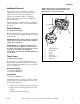
Installation Additional Security Torx security screws are available (as optional equipment at extra cost) for securing lower access panel to dryer base. Order part number 62853. NOTE: Adjust ratchet wheel and timing cam to “OFF” position prior to putting dryer into use. Refer to Figure 1 for proper position. 1 A Torx bit, part number 282P4, is available (as optional equipment at extra cost) for installing the Torx security screws.
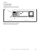
Installation Coin Slide Guards (Coin Slide Models Only) Using sheet metal screws from accessories bag, install coin slide guard, to front of control cabinet. Refer to Figure 2. 1 OPERATING INSTRUCTIONS PERM PRESS 1. Select Fabric Type (heat setting) NORMAL, PERM PRESS, DELICATE, FLUFF (no heat) DELICATE 2. Load Clothes. FLUFF (NO HEAT) NORMAL 3. Insert Coin(s)/Card. IN USE FABRIC SELECTOR 4. To Start Dryer - Close Door and Push Start. 5. To Stop Dryer During Cycle - Open Door. 6.
Installation Before You Start No other fuel burning appliance should be installed in the same closet with the dryer. Tools For most installations, the basic tools you will need are: 1 2 The dryer must not be installed or stored in an area where it will be exposed to water and/or weather. The dryer needs sufficient clearance and an adequate air supply for proper operation and ventilation, and for easier installation and servicing. (Minimum clearances are shown in Figure 4).
Installation B E D A A *42" (107 cm) C A 1 SIDE VIEW FRONT VIEW (w/o Closet Door) Area Description Free Standing/Alcove Installation A Dryer sides and rear clearance 0 in. (0 cm) B Dryer top clearance 12 in. (30.5 cm) C Dryer front clearance Not Applicable D Exhaust duct clearance to combustible material 2 in. (5.1 cm) E Weather hood to ground clearance 12 in. (30.5 cm) (Minimum clearances are shown.
Installation Step 2: Connect Dryer Exhaust System ● DO NOT use plastic or thin foil ducting. Rigid metal duct is recommended. WARNING To reduce the risk of fire and combustion gas accumulation the dryer MUST be exhausted to the outdoors. W604 To reduce the risk of fire and the accumulation of combustion gases, DO NOT exhaust dryer air into a window well, gas vent, chimney or enclosed, unventilated area, such as an attic, wall, ceiling, crawl space under a building or concealed space of a building.
Installation ● Static pressure in exhaust duct should not be greater than .6 inches water column (1.5 cm), measured with manometer placed on exhaust duct two feet (61 cm) from dryer (check with dryer running and no load). In multi-dryer installations, all dryers connected to the main collector duct should be operating when pressure is checked. ● Exhausting dryer in hard-to-reach locations can be done by installing 521P3 Flexible Metal Vent Kit (available as optional equipment at extra cost).
Installation Exhaust System NOTE: Weather hood should be installed at least 12 inches (30.5 cm) above the ground. Larger clearances may be necessary for installations where heavy snowfall can occur. For best drying results, recommended maximum length of exhaust system is shown in Table 1. To prevent backdraft when dryer is not in operation, outer end of exhaust pipe must have a weather hood with hinged dampers (obtain locally). Number of 90° Elbows Recommended 4 in. (10.
Installation Multi-Dryer Installation Exhaust Requirements Figure 7 shows a typical example of a multiple dryer installation. Note how each dryer has its own exhaust system vented to the central exhaust duct. 2 1 S TION RUC INST ) S, ING (heat setting heat) RAT Type PRES (no OPE FabricAL, PERM FLUFF 1. 2. 3. 4. 5. 6. SelectNORMATE, DELIC Start. s. Push . Clothe and )/Card Door Door. Coin(s Close Start. - Open Push Cycle Dryer and During Door Dryer Close When lete rt Dryer is Comp Off.
Installation 1 A B C D E F G H I J 2 K 5 3 AIR FLOW 4 EXHAUST AIR FLOW MAXIMUM LENGTH OF DUCT 30 feet (9.1 m) 30° EXHAUST OUTLET 24 in. (61 cm) MINIMUM CLEARANCE TO ROOF/GROUND D686I HORIZONTAL EXHAUST INSTALLATION D686I 1 2 NOTE: Where the exhaust duct pierces a combustible wall or ceiling, the opening must be sized per local codes. Wall 3 4 5 2 in. (5 cm) Minimum or Clearance per Local Codes No Screen or Cap Clean Out Cover – Inspect Monthly Figure 8 2 WARNING 24 in.
Installation Duct Station Minimum Diameter of Collector Duct A 4 inches (10.2 cm) B 8 inches (20.3 cm) C 9 inches (22.9 cm) D 10 inches (25.4 cm) E 11 inches (27.9 cm) F 12 inches (30.5 cm) G 13 inches (32.6 cm) H 14 inches (35.6 cm) I 15 inches (38.1 cm) J 15 inches (38.1 cm) K 16 inches (40.6 cm) 1. Make certain your dryer is equipped for use with the type of gas in your laundry room. Dryer is equipped at the factory for Natural Gas with a 3/8 inch NPT gas connection.
Installation NOTE: When connecting to a gas line, an equipment shut-off valve must be installed within 6 feet (1.8 m) of the dryer. An 1/8 in. NPT pipe plug must be installed as shown for checking inlet pressure. Refer to Figure 10. 1 3 Step 4: (Electric Dryer Only) Connect Electrical Plug Dryer requires 120/240 Volt or 120/208 Volt, 60 Hertz, 3 or 4 wire electrical supply. Refer to serial plate for specific electrical requirements.
Installation Grounding Information ● ● 18 This dryer must be connected to a grounded metal, permanent wiring system; or an equipment-grounding conductor must be run with the circuit conductors and connected to the equipment-grounding terminal or lead on the dryer. The dryer has its own terminal block that must be connected to a separate branch, 60 Hertz, single phase circuit, AC (alternating current) circuit, fused at 30 Amperes (the circuit must be fused on both sides of the line).
Installation IMPORTANT: Use only a new U.L. listed No. 10 (copper wire only) three conductor power supply cord kit rated 240 Volts (minimum) 30 Amperes and labeled as suitable for use in a clothes dryer.
Installation Connecting Power Cord with Three-Wire Plug NOTE: Four-wire cord is required for mobile homes or where codes do not permit grounding through neutral. NOTE: The power cord is NOT supplied with the electric dryer. Type of power cord and gauge of wire must conform to local codes and instructions. POWER SUPPLY POWER SUPPLY 1 The method of wiring the dryer is optional and subject to local code requirements.
Installation 4. Use the three screws from the accessories bag to attach the power cord wires to the terminal block. Refer to Figure 16. 1 2 1 3 2 12 V. 0 ± A 1 .C 2 . 4 12 V. 0 ± A 1 .C 2 . 240 ± 12 V.A.C. 12 V. 0 ± A 1 .C 2 . 12 V. 0 ± A 1 .C 2 . 3 0 V.A.C. D286I 1 2 3 “L1” Terminal Neutral Terminal “L2” Terminal Figure 16 5. Tighten all screws firmly. IMPORTANT: Failure to tighten these screws firmly may result in wire failure at the terminal block.
Installation 3. Remove ground screw and save for use in Step 5. Remove wire and use in Step 6. 5. Attach power cord ground (green) wire to rear bulkhead using ground screw removed in Step 3. 1 1 7 6 5 D697I 2 4 D697I 1 Ground Screw DRY1920N 3 Figure 19 DRY1920N 4. Use a strain relief and insert end of power cord through power supply hole. 1 2 3 4 5 6 7 White “L2” Terminal Black Green Red Neutral Terminal “L1” Terminal Figure 21 6.
Installation Step 5: Reverse Door, if Desired 4. Rotate door panel 180 degrees as shown. The door on this dryer is completely reversible. To reverse door proceed as follows: 1. Remove four hinge attaching screws. S ON CTI TRU INS g) ING (heat settinS, heat) RATc Type PRES F (no OPE t Fabri PERM FLUF 1. 2. 3. 4. 5. 6. MAL, , SelecNORCATE DELI Start. es. Push Cloth rd. and Load Door. s)/Ca Door t Coin( - Close Start.
Installation 8. Using screwdriver, remove two door plugs, and reinstall on opposite side of door opening. INS Electric Dryer Connect the dryer to an electrical power source. Refer to Step 4 for information on connecting power cord. NS TIO TR Step 7: Plug In the Dryer UC g) ING (heat settin SS, ) AT heat M PRE (no ER ic Type , PER F ct FabrMAL FLUF Sele NORICATE, . DEL Start es. Push Cloth . and ard. Load Door (s)/C .
Installation The dryer is designed to be operated on a separate branch, polarized, three-wire, effectively grounded, 120 Volt, 60 Hertz, AC (alternating current) circuit protected by a 15 Ampere fuse, equivalent fusetron or circuit breaker. The three-prong grounding plug on the power cord should be plugged directly into a polarized three-slot effectively grounded receptacle rated 120 Volts AC (alternating current) 15 Amps. Refer to Figure 33 to determine correct polarity of the wall receptacle.
Installation Gas Dryers After the dryer has operated for approximately five minutes, observe burner flame through lower front panel. Adjust the air shutter to obtain a soft, uniform blue flame. (A lazy, yellow-tipped flame indicates lack of air. A harsh, roaring, very blue flame indicates too much air.) Adjust the air shutter as follows: IMPORTANT: This operation is to be conducted by qualified personnel only. To view the burner flame, remove the lower front panel of the dryer.
Operation Operation Instructions for Electromechanical Dryers Step 2: Load Laundry Load clothes loosely into dryer drum. Add fabric softener sheet if desired. WARNING To reduce the risk of fire, electric shock, or injury to persons, read the IMPORTANT SAFETY INSTRUCTIONS before operating this appliance. OPERATING INSTRUCTIONS PERM PRESS NORMAL 1. Select Fabric Type (heat setting) NORMAL, PERM PRESS, DELICATE, FLUFF (no heat) DELICATE 2. Load Clothes. FLUFF (NO HEAT) 3. Insert Coin(s)/Card.
Operation Step 4: Set Fabric Selector Step 5: Start Dryer Select NORMAL for cottons, PERM PRESS for permanent press, DELICATE for sensitive items or FLUFF (NO HEAT) for items that require no heat. Place coin(s) in slide and carefully push in as far as possible and then pull slide out as far as possible. After IN USE light comes on (indicating start of cycle), press the PUSH-TO-START button. NOTE: Always follow manufacturer’s care label instructions.
Operation Operation Instructions for Electronic Display Control Dryers Step 2: Load Laundry Load clothes loosely into dryer drum. Add fabric softener sheet if desired. WARNING To reduce the risk of fire, electric shock, or injury to persons, read the IMPORTANT SAFETY INSTRUCTIONS before operating this appliance. OPERATING INSTRUCTIONS 1. Select Fabric Type (heat setting) NORMAL, PERM PRESS, DELICATE, FLUFF (no heat) 2. Load Clothes. 3. Insert Coin(s)/Card. 4. To Start Dryer - Close Door and Push Start.
Operation Step 4: Set Fabric Selector To Insert Card Select HIGH TEMP, MED TEMP, LOW TEMP or NO HEAT by pushing touchpad. Insert card into opening. Follow directions on display. DO NOT REMOVE THE CARD UNTIL DISPLAY READS “Remove Card”. NOTE: Always follow manufacturer’s care label instructions. HIGH TEMP START MED TEMP LOW TEMP NO HEAT M330I M330I D452I Figure 45 D452I If Additional Time Feature is turned on, additional dryer time may be purchased at cycle start or while dryer is running.
Operation Indicator Lights DOOR OPEN INSERT COINS DOOR OPEN is lit and flashes at one-second intervals whenever the dryer door is open. INSERT COINS is lit to prompt the user to insert coins or card to satisfy the vend price for the chosen cycle. When INSERT COINS is lit, the three digits and decimal point will display the vend price remaining to be satisfied. COOL DOWN COOL DOWN is lit whenever the COOL DOWN portion of a heated cycle is active. It is also lit when the NO HEAT cycle is in operation.
Operation Operation Instructions for MDC Dryers Step 2: Load Laundry Load clothes loosely into dryer drum. Add fabric softener sheet if desired. WARNING To reduce the risk of fire, electric shock, or injury to persons, read the IMPORTANT SAFETY INSTRUCTIONS before operating this appliance. OPERATING INSTRUCTIONS 1. Select Fabric Type (heat setting) NORMAL, PERM PRESS, DELICATE, FLUFF (no heat) 2. Load Clothes. 3. Insert Coin(s)/Card. 4. To Start Dryer - Close Door and Push Start. 5.
Operation Step 4: Set Fabric Selector To Insert Card Select HIGH TEMP, MED TEMP, LOW TEMP or DELICATES by pushing touchpad. Insert card into opening. NOTE: Always follow manufacturer’s care label instructions. DRY1926N DRY1926N DRY1927N Figure 50 Figure 52 Step 5: Insert Coin(s) or Card If Additional Time Feature is turned on, additional dryer time may be purchased at cycle start or while dryer is running. To Insert Money Insert coin(s) in coin slot. Check pricing as seen on digital display.
Operation Indicator Lights START START is lit whenever the dryer is not in a cycle, the full vend price has been satisfied and the dryer door is closed. When the START pad is pressed, the cycle will begin or resume. DRYING DRYING is lit to indicate that one of the heated cycles (HIGH TEMP, MED TEMP, LOW TEMP or DELICATES) is currently in operation. DRYING will turn off at the end of a heated cycle or when the COOL DOWN cycle begins.
Operation Operation Instructions for NetMaster Dryers Step 2: Load Laundry Load clothes loosely into dryer drum. Add fabric softener sheet if desired. WARNING To reduce the risk of fire, electric shock, or injury to persons, read the IMPORTANT SAFETY INSTRUCTIONS before operating this appliance. OPERATING INSTRUCTIONS 1. Select Fabric Type (heat setting) NORMAL, PERM PRESS, DELICATE, FLUFF (no heat) 2. Load Clothes. 3. Insert Coin(s)/Card. 4. To Start Dryer - Close Door and Push Start. 5.
Operation Step 4: Set Fabric Selector To Insert Card Select HIGH TEMP, MED TEMP, LOW TEMP or NO HEAT by pushing touchpad. Insert card into opening. DO NOT REMOVE THE CARD UNTIL THE REMOVE CARD LED IS LIT. NOTE: Always follow manufacturer’s care label instructions. D777I M343I M343I D777I Figure 59 Figure 57 If Additional Time Feature is turned on, additional dryer time may be purchased at cycle start or while dryer is running.
Operation Indicator Lights COOL DOWN INSERT COINS/CARD COOL DOWN is lit whenever the COOL DOWN portion of a heated cycle is active. It is also lit when the NO HEAT cycle is in operation. INSERT COINS/CARD is lit to prompt the user to insert coins or a card to satisfy the vend price. When INSERT COINS/CARD is lit, the three digits and decimal point will display the vend price remaining to be satisfied.
Maintenance Lubrication Exhaust System All moving parts are sealed in a permanent supply of lubricant or are equipped with oilless bearings. Additional lubrication will not be necessary. WARNING To reduce the risk of electric shock, disconnect the electrical service to the dryer before cleaning. Care of Your Dryer WARNING W043 To reduce the risk of an electric shock, serious injury or death, disconnect the electrical service to the dryer before cleaning the interior.
Maintenance Motor Overload Protector The dryer’s motor overload protector stops the motor automatically in the event of an overload. After cooling, the overload protector will reset itself. Dryer can be restarted by pressing the PUSH-TO-START button or START pad. If overload protector cycles again, remove the dryer from use and call the service person to correct the problem. 510977 For Energy Conservation ● Make sure the lint filter is always clean. ● Do not overload dryer. ● Do not overdry clothes.
Troubleshooting Try these troubleshooting tips before making a service call. They may save you time and money. Dryer Symptom Possible Cause/Solution • • • • Dryer won’t start • • • • • • • Dryer won’t heat • • • • Dryer doesn’t dry clothes satisfactorily • • • • • • Dryer is noisy • • Nonmetered models - Turn timer knob further into cycle. Metered models - Insert coin(s) or card. Metered models - Activate timer. Push coin slide all the way in.
Contact Information If service is required, contact the nearest Factory Authorized Service Center. WARNING If you are unable to locate an authorized service center or are unsatisfied with the service performed on your dryer, contact: Alliance Laundry Systems Shepard Street P. O. Box 990 Ripon, WI 54971-0990 U.S.A. www. comlaundry.
Installer Checklist Fast Track for Installing the Dryer (Refer to the manual for more detailed information) 1 6 • Position and Level the Dryer. • Wipe Out Inside of Dryer. setting) (heatPRESS, heat) Type (no PERM Fabric FLUFF , 1.SelectNORMAL, DELICATE Start. Push Clothes. rd. and Door. Door Coin(s)/CaClose Start. - Open Push When 3.Insert Dryer Cycle and Start During Door 4.To is Complete Off. Dryer Close CycleGoes Stop Dryer DryingLight 5.To Restart Panel 6.To 2.