Programming Washer-Extractors UW Pocket Hardmount B-Series Microcomputer 2 Speed Models UW35B2 and UW60B2 NORMAL WASH ADD BLEACH RINSE SPIN DOOR NOTA: El manual en español aparece después del manual en inglés. PERM PRESS HOT HOT LIGHT SOIL VISA TM HOT WARM HEAVY SOIL UNIFORMS START HOT HOT STAINED DELICATE HOT COLD DOMESTIC MODELS 95C 95C 60C 60C 40C 40C 30C < < INTERNATIONAL MODELS PHM1392C PHM1 www.comlaundry.com Part No.
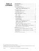
Table of Contents Safety Information.............................................................................. Important Safety Instructions ............................................................... 3 3 Programming ...................................................................................... Entering Program Mode ....................................................................... Determining Firmware ID Code...........................................................
Notes 2 © Copyright, Alliance Laundry Systems LLC – DO NOT COPY or TRANSMIT F232168
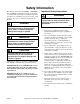
Safety Information Precautionary statements (“DANGER,” “WARNING,” and “CAUTION”), followed by specific instructions, are found in this manual and on machine decals. These precautions are intended for the personal safety of the operator, user, servicer, and those maintaining the machine.
Safety Information 9. Do not install or store the washer where it will be exposed to water and/or weather. 10. Do not tamper with the controls. 11. Do not repair or replace any part of the washer, or attempt any servicing unless specifically recommended in the user-maintenance instructions or in published user-repair instructions that the user understands and has the skills to carry out. 12.
Programming NOTE: The machines are factory-programmed with basic cycles to make the units operational without programming at the installation. Entering Program Mode 1. Open control compartment lid. 2. Locate Program/Run switch on the computer board. (This is accessed through a cutout in the metal control unit cover.) This switch protrudes from the rear of the electronic control unit cover. 3. Flip switch to the left (as seen from the front of machine) to enter Program Mode. 4.
Programming Setup Mode (For Models With Firmware ID Code “o2HC”, “o2UC”, “ouHC” and “ouUC”) NOTE: In Setup Mode, certain machine functions can be configured. The settings in this mode are related to how the machine is equipped from the factory. Usually, these would not be changed in this field. NOTE: Enter Setup Mode through the Program Mode. 1. Press (*) key. Display will show “FAr” or “CEL”.
Programming Setup Mode (For Earlier Models) NOTE: In Setup Mode, certain machine functions can be configured. The settings in this mode are related to how the machine is equipped from the factory. Usually, these would not be changed in this field. NOTE: Enter Setup Mode through the Program Mode. 1. Press (*) key. Display will show “FAr” or “CEL”. NOTE: This selects whether temperatures display in degrees Fahrenheit (F) or Celsius (C), if control is equipped with a temperature sensor.
Programming Programming Cycle Segments After entering Program Mode, display will show a temperature. Press the (∧) key to enter Cycle Programming Mode. The display will reference cycles by number. Cycle 1 will show first. Use the (∧) or (∨) key to select cycle to be edited. Press START key to move into the following menu of options (starting at Table 1). The machine is preprogrammed with eight wash cycle formulas that can be edited. To edit any of these cycles, enter Program Mode.
Programming Options for Each Segment Cycle Steps Available (NOTE: WASH, ADD BLEACH, RINSE, and SPIN LEDs light ONLY when a cycle formula is in operation.) Setting Options for Cycle Steps (Press START key to advance to next row selection, (∧) to increase a value or change, (∨) to decrease a value or change, or (∗) to save and exit.
Programming Table 1 (Continued) Cycle Steps Available (NOTE: WASH, ADD BLEACH, RINSE, and SPIN LEDs light ONLY when a cycle formula is in operation.) Setting Options for Cycle Steps (Press START key to advance to next row selection, (∧) to increase a value or change, (∨) to decrease a value or change, or (∗) to save and exit.
Programming Table 1 (Continued) Cycle Steps Available (NOTE: WASH, ADD BLEACH, RINSE, and SPIN LEDs light ONLY when a cycle formula is in operation.) Setting Options for Cycle Steps (Press START key to advance to next row selection, (∧) to increase a value or change, (∨) to decrease a value or change, or (∗) to save and exit.
Programming Table 1 (Continued) Cycle Steps Available (NOTE: WASH, ADD BLEACH, RINSE, and SPIN LEDs light ONLY when a cycle formula is in operation.) Setting Options for Cycle Steps (Press START key to advance to next row selection, (∧) to increase a value or change, (∨) to decrease a value or change, or (∗)to save and exit.
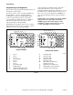
Programming To Edit an Entire Wash Cycle Formula Enter Program Mode. Press the (∧) key until display shows “CY01”. Press the (∧) or (∨) key until cycle to be edited is displayed; then press START key to select the cycle desired. Refer to Figure 1, showing which cycle number corresponds to each key when in Run Mode. Agitation for the Cycle With display showing “CY_x” (x = cycle number), press the START key. Display shows either “norn” (for normal agitation), or “GEnt” (for gentle agitation).
Programming Heated Models Only Rinse 1 – Rinse 4 Display shows temperature in degrees F or C. Display will show degrees F if configured for “FAr” in Setup Mode, or degrees C if configured for “CEL” in Setup Mode. Range is 80°F to 205°F, or 00F (no heat for segment), or 27°C to 95°C, or 00C (no heat for segment). NOTE: Programming a time other than “00” for this step will make the RINSE indicator LED light while this step is running, but not in Program Mode.
Programming The washer-extractor has 5 supply compartments, designated as compartments 1, 2, 3, 4 and 5. Compartment 1 is farthest to the rear of machine. Moving toward the front of machine, compartments are ordered 2, 3, 4 and 5 (at the front of machine). Supply signals 1 through 5 correspond to compartments 1 through 5. Supply signals 1, 2, and 3 have dedicated water valves that flush compartments 1, 2 and 3 (along with the signal being available for external supplies).
Programming Abnormal Conditions Temperature Probe Sensor Problem Door Open During Operation If display shows “tSFL”, “-19c”, or “00F”, the machine has a temperature sensor failure. This could mean the sensor is not connected or the sensor has failed. If replacing the probe does not correct this, consult an authorized service person.
Programming Rapid Advance (For Models With Firmware ID Code “o2HC”, “o2UC”, “ouHC” and “ouUC”) NOTE: Rapid Advance (“Adv”) possible only if configured for “Adv” in Setup mode. Refer to Setup Mode. How to Rapid Advance During All Steps (Except First Fill Step) 1. Make sure Rapid Advance is enabled. 2. Press the advance (∧) keypad to advance to desired step. 3. Display will show recalculated time remaining. How to Rapid Advance (During First Fill Step) 1. Make sure Rapid Advance is enabled. 2.
Programming Permanent Diagnostic Test Cycle Control Test Warm fill to low water level Display flashes “bFIL”/“LO” (WASH LED on), no agitation Outputs: Motor OFF, Drain closed, hot fill on, cold fill on Pause after reaching low water level Display shows “LO” (no flashing), LOW water level dot ON, no agitation (keypad WASH LED on); pauses until operator presses (∧) key Outputs: Motor OFF, Drain closed Drain (can advance to next step Display shows “drAI”, no agitation (keypad WASH LED on) by pressing (∧)
Programming Table 2 (Continued) Pause 5 seconds, then Reverse Display shows ‘rEv’ wash speed – 60 seconds, pause Outputs: Motor operates wash speed reverse; drain closed several seconds before entering drain (next step) Drain (cannot advance to spin here) For 2 speed models: Display flashes “drAI”/“For” (keypad RINSE LED on) For variable-speed models: Display flashes “drAI”/“For” while operating in low speed forward; then flashes “drAI”/“dISt” while operating at distribution speed.
Programming Cycle Charts for Domestic OPL Models Built After April 2005 (Displays P-F5) Displays P-F5 after power is applied to machine when START (enter) keypad is pressed while display shows “- - - -”.
Programming Table 3 (Continued) Normal Hot Light Soil Hot Heavy Soil Hot Stained Hot Perm Press Hot Visa® Warm Uniforms Delicate Cold 2 2 2 2 4 2 2 2 Fill valves (temperature) Hot Warm (Both) Hot Warm (Both) Hot Warm (Both) Warm (Both) Cold Fill water level High High High High High High High High Supply 0 0 0 0 0 0 0 0 Heat (if enabled) 0 0 0 0 0 0 0 0 Yes Yes Yes Yes Yes Yes Yes Yes 0 0 0 0 0 0 0 0 2 2 2 2 2 2 2 2 Warm (Both) Warm
Programming Table 3 (Continued) Cycle Steps Normal Hot Light Soil Hot Heavy Soil Hot Stained Hot Perm Press Hot Visa® Warm Uniforms Delicate Cold 4 4 4 4 4 4 4 2 Warm (Both) Warm (Both) Warm (Both) Warm (Both) Warm (Both) Warm (Both) Warm (Both) Cold Rinse 4 (RINSE indicator) Time for agitation Fill valves (temperature) Fill water level Low Low Low Low Low Low Low Low Supply 3 3 3 3 3 3 3 3 Heat (if enabled) 0 0 0 0 0 0 0 0 Yes Yes Yes Yes Yes Yes Ye
Programming Cycle Charts for Domestic OPL Models Built Prior to April 2005 (Displays P-F1) Displays P-F1 after power is applied to machine when START (enter) keypad is pressed while display shows “- - - -”.
Programming Table 4 (Continued) Normal Hot Cycle Steps Light Soil Hot Heavy Soil Hot Stained Hot 2 4 Perm Press Hot Visa® Warm Uniforms Delicate Cold Wash 4 (WASH indicator) Time for agitation 2 Fill valves (temperature) Hot Hot Both Fill water level High High High Supply 0 0 0 Heat (if enabled) 0 0 0 Yes Yes Yes 0 0 0 Drain Spin (only if ‘drain’) seconds Rinse 1 (RINSE indicator) Time for agitation 4 4 4 4 4 2 4 Fill valves (temperature) Hot Hot Hot Hot Hot
Programming Table 4 (Continued) Normal Hot Light Soil Hot Heavy Soil Hot Stained Hot Perm Press Hot Visa® Warm Uniforms Delicate Cold 4 4 3 3 4 4 4 2 Fill valves (temperature) Both Both Both Both Both Both Both Cold Fill water level Cycle Steps Rinse 4 (RINSE indicator) Time for agitation Low Low Low Low Low Low Low High Supply 3 3 3 3 3 0 3 3 Heat (if enabled) 0 0 0 0 0 0 0 0 Yes Yes Yes Yes Yes Yes Yes Yes 6 6 6 6 4 3 4 4 Drain Spin (onl
Programming Cycle Charts for International OPL Normal Normal Normal 95°C 60°C 40°C Gentle Cold Perm Press 95°C Perm Press 60°C Perm Press 40°C Gentle 30°C 12/3/12 Normal 12/3/12 Normal 12/3/12 Normal 3/12/3 Gentle 12/3/12 Normal 12/3/12 Normal 3/12/3 Gentle 3/12/3 Gentle Time for agitation (min) 2 2 2 2 2 2 2 2 Fill valves (temperature) Both Both Both Cold Both Both Both Cold Fill water level Low Low Low High Low Low Low High 1 1 1 1 1 1 1 1 Heat (if enabled
Programming Table 5 (Continued) Normal 95°C Cycle Steps Normal 60°C Normal 40°C Gentle Cold Perm Press 95°C Perm Press 60°C Perm Press 40°C Gentle 30°C Wash 4 (WASH indicator) Time for agitation Fill valves (temperature) Fill water level Supply Heat Drain Spin (only if ‘drain’) seconds Rinse 1 (RINSE indicator) Time for agitation Fill valves (temperature) Fill water level Supply Heat Drain Spin (only if ‘drain’) seconds Rinse 2 (RINSE indicator) Time for agitation 2 2 2 2 2 2 2 Fill valves
Programming Table 5 (Continued) Normal 95°C Normal 60°C Normal 40°C Gentle Cold Perm Press 95°C Perm Press 60°C Perm Press 40°C Gentle 30°C Time for agitation (min) 2 2 2 2 2 2 2 2 Fill valves (temperature) Cold Cold Cold Cold Cold Cold Cold Cold Fill water level High High High High High High High High 0 0 0 0 0 0 0 0 Heat (if enabled) No No No No No No No No Drain Yes Yes Yes Yes Yes Yes Yes Yes Spin (only if ‘drain’) seconds 60 60 60 60 60