Installation Washer-Extractors UW Pocket Hardmount 2 Speed P029I P031I Para bajar una copia de estas instrucciones en español, visite www.comlaundry.com. Keep These Instructions for Future Reference. (If this machine changes ownership, this manual must accompany machine.) www.comlaundry.com Part No.
Table of Contents Introduction......................................................................................... Model Identification ............................................................................. 3 3 Safety Information.............................................................................. 5 Explanation of Safety Messages........................................................... 5 Important Safety Instructions ...............................................................
Notes 2 © Copyright, Alliance Laundry Systems LLC – DO NOT COPY or TRANSMIT F232085
Introduction Model Identification F232085 UW35B2 UW35P2 UW60B2 UW60P2 UW35M2 UW35S2 UW60M2 UW60S2 © Copyright, Alliance Laundry Systems LLC – DO NOT COPY or TRANSMIT 3
Notes 4 © Copyright, Alliance Laundry Systems LLC – DO NOT COPY or TRANSMIT F232085
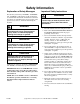
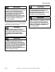
Safety Information Explanation of Safety Messages Precautionary statements (“DANGER,” “WARNING,” and “CAUTION”), followed by specific instructions, are found in this manual and on machine decals. These precautions are intended for the personal safety of the operator, user, servicer, and those maintaining the machine. Important Safety Instructions WARNING To reduce the risk of fire, electric shock, serious injury or death to persons when using your washer, follow these basic precautions: W023 DANGER 1.
Safety Information 9. Do not install or store the washer where it will be exposed to water and/or weather. 10. Do not tamper with the controls. 11. Do not repair or replace any part of the washer, or attempt any servicing unless specifically recommended in the user-maintenance instructions or in published user-repair instructions that the user understands and has the skills to carry out. 12.
Safety Information CAUTION WARNING Dangerous voltages are present in the electrical control box(es) and at the motor terminals. Only qualified personnel familiar with electrical test procedures, test equipment, and safety precautions should attempt adjustments and troubleshooting. Disconnect power from the machine before removing the control box cover, and before attempting any service procedures. SW005 Warnings are general examples that apply to this machine.
Safety Information Safety Decals Safety decals appear at crucial locations on the machine. Failure to maintain legible safety decals could result in injury to the operator or service technician. 8 To provide personal safety and keep the machine in proper working order, follow all maintenance and safety procedures presented in this manual. If questions regarding safety arise, contact the factory immediately. Use factory-authorized spare parts to avoid safety hazards.
Safety Information Operator Safety Safe Operating Environment WARNING NEVER insert hands or objects into basket until it has completely stopped. Doing so could result in serious injury. SW012 To ensure the safety of machine operators, the following maintenance checks must be performed daily: Safe operation requires an appropriate operating environment for both the operator and the machine. If questions regarding safety arise, contact the factory immediately.
Safety Information For machines equipped with optional steam heat, install piping in accordance with approved commercial steam practices. Failure to install the supplied steam filter may void the warranty. DANGER Do not place volatile or flammable fluids in any machine. Do not clean the machine with volatile or flammable fluids such as acetone, lacquer thinners, enamel reducers, carbon tetrachloride, gasoline, benzene, naptha, etc.
Installation This manual is designed as a guide to the installation and maintenance of the UW35 and UW60 2 speed rigid-mount washer-extractor. Water enters the machine through electromechanical water valves. Vacuum breakers are installed in the water-inlet plumbing to prevent backflow of water. All information, illustrations, and specifications contained in this manual are based on the latest product information available at the time of printing.
Installation Delivery Inspection Serial Plate Location Upon delivery, visually inspect crate, protective cover, and unit for any visible shipping damage. If the crate, protective cover, or unit are damaged or signs of possible damage are evident, have the carrier note the condition on the shipping papers before the shipping receipt is signed, or advise the carrier of the condition as soon as it is discovered. A record of each machine is on file with the manufacturer.
Installation Model Number Familiarization Guide Sample Model Number: UW60P2OU70001 UW Model Number Prefix 60 Washer-Extractor Capacity (pounds dry weight) P (S) (M) (B) Type of Electrical Control P = WE-6 Computer S = 12 Cycle Computer M = Mechanical Timer B = Millenium Computer 2 Washer-Extractor Speed Capabilities 2 = 2 Speeds O Electrical Characteristics Refer to Table 8.
Installation . UW 2 Speed Pocket Hardmount Models Specifications UW35 UW60 Overall width, in. (mm) 32-1/2 (826) 36-5/8 (930) Overall height, in. (mm) 55-1/2 (1410) 64-1/2 (1638) Overall depth, in. (mm) 38-1/4 (972) 45 (1143) 750 (341) 1136 (515) 74 (34) 200 (92) 810 (367) 1175 (533) 66 (1.9) 84 (2.4) 38 x 47 x 64 (970 x 1200 x 1630) 40 x 49 x 74-1/2 (1016 x 1245 x 1892) 910 (413) 1300 (590) 78 (2.2) 96 (2.
Installation UW 2 Speed Pocket Hardmount Models Specifications UW35 UW60 1 1 Wash/reverse motor power, hp (kW) 0.4 (0.3) 0.6 (0.5) High extract motor power, hp (kW) 1.8 (1.3) 3.0 (2.2) Wash/reverse speed, rpm/g 50 / 0.95 44 / 0.88 Distribution speed, rpm/g – – High extract speed, rpm/g 504 / 95 465 / 98 Vibration safety switch installed N/A STD Safety switch gap setting, in. (mm) N/A 0.008-0.010 (0.20-0.25) 1/2 (13) 1/2 (13) 1 1 LOW 2.1 (1.5) 3.3 (2.4) MED 2.3 (1.7) 3.
Installation Machine Dimensions Dimensional Clearances NOTE: The dimensions shown here are for planning purposes only. They are approximate and subject to normal manufacturing tolerances. If exact dimensions are required for construction purposes, contact the distributor or manufacturer. We reserve the right to make changes at any time without notice. Dimensions Allow a minimum of 24 inches (60 cm) at the rear and 18 inches (45 cm) at the sides for maintenance, inspection, and adjustment.
Installation 1 2 3 4 F E C G (Base) A (Base) B (Overall) D (Overall) 5 8 6 I 7 H PHM388N UWP2 MODEL SHOWN PHM388N 1 2 3 4 Supply Valve Box Supply Dispenser Door Handle Spray Rinse Nozzle 5 6 7 8 Water Inlet Valves Power Input Area (Inside) Drain Steam Connection (Optional) Figure 2 F232085 © Copyright, Alliance Laundry Systems LLC – DO NOT COPY or TRANSMIT 17
Installation Machine Foundation A proper foundation is absolutely necessary for UW 2 speed washer-extractors because of the high extract speed and the G-forces exerted. Do not mount on wooden floors, above ground level, or over basements. Installation must be “slab on grade” or equal. Thoroughness of detail must be stressed with all foundation work to ensure a stable unit installation, eliminating possibilities of excessive vibration during extract.
Installation Mechanical Installation Mounting Bolt Installation A bolt kit is available as an option. The UW35 uses 5/8-11 x 6 inch bolts; the UW60 uses 3/4-10 x 8 inch bolts. The bolts should be embedded in a 3500 psi minimum reinforced concrete floor that is a minimum of 6 inches (15 cm) thick. For mounting bolt layouts for both machines, refer to Figures 3 and 4. (The front of the washer-extractor is the bottom of the diagram.
Installation Mounting Bolt Hole Locations 28-5/8 in. (727 mm) 39-1/32 in. (991 mm) 3/4 in. (19 mm) 22-3/4 in. (578 mm) 29 in. (737 mm) 30-1/2 in. (774 mm) OUTLINE OF FRAM BASE 35-1/8 in. (892 mm) FRONT 2 in. (51 mm) 26-1/8 in. (664 mm) 2 in. (51 mm) 30-1/8 in.
Installation 3/4 in. (19 mm) 34-1/8 in. (867 mm) 3/4 in. (19 mm) 3/4 in. (19 mm) 4-3/16 in. (122 mm) 46-13/16 in. (1189 mm) 9 in. (229 mm) 36 in. (914 mm) 1-1/4 in. (32 mm) 44-13/16 in. (1138 mm) 1-1/4 in. (32 mm) 39-1/4 in. (997 mm) 21-7/16 in. (554 mm) 3/4 in. (19 mm) 31-3/4 in. (803 mm) 2 in. (51 mm) 2 in. (51 mm) 35-5/8 in.
Installation The threaded end of the bolts should extend 2 inches (5 cm) above the surface of the floor. 1 Refer to Figure 5 for a typical installation of individual mounting bolts on a UW60. 2 3 3/4 in. (19 mm) 1 2 2 in. (51 mm) 4 8 in. (203 mm) P03 I PHM178N 1 2 Frame Grout 1 2 3 4 P035I Machine Base Mounting Bolt Threads Grouting Reinforcing Rod Figure 6 Figure 5 A bolt-locator fixture or rebar frame is available as an option.
Installation After the concrete has cured, proceed as follows: 35-5/8 in. (905 mm) 1. Place the washer-extractor adjacent to the foundation. Do not attempt to move the machine by pushing on the sides. Always insert a pry bar or other device under the bottom frame of the machine to move it. 2. Remove the wood skid by unscrewing the carriage bolts holding the skid to the bottom frame of the washer-extractor. 5.
Installation Drain Connection A drain system of adequate capacity is essential to washer-extractor performance. Ideally, the water should empty through a vented pipe directly into a sump or floor drain. Figures 9 and 10 show drain line and drain trough configurations. If proper drain size is not available or practical, a surge tank is required. A surge tank in conjunction with a sump pump should be used when gravity drainage is not possible, such as in below-ground-level installations.
Installation Refer to Table 4 for capacity-specific drain information. 1 2 Installation of additional washer-extractors will require proportionately larger drain connections. Refer to Table 5. UW 2 Speed Pocket Hardmount Drain Information 35 60 2-3/8 (60) 3 (76) 1 1 Drain flow capacity, gal/min (l/min) 35 (132) 64 (242) Recommended drain pit size, ft3 (l) 5 (142) 6 (170) Drain connection size, I.D., in.
Installation Water Connection UW 2 Speed Pocket Hardmount Water Supply Line Sizing UW 2 Speed Pocket Hardmount Water Supply Information Water inlet connection size, in. (mm) 3/4 (19) Number of water inlets (standard) 4* Recommended pressure psi (bar) 30 – 85 (2 – 5.7) Inlet flow capacity, gal/min (l/min) (80 psi) 35 28 (106) 60 39 (148) 35 *M and B models have two connections. Table 6 Connections should be supplied by hot and cold water lines of at least the sizes shown in Table 7.
Installation Electrical Installation IMPORTANT: Electrical ratings are subject to change. Refer to serial decal for electrical ratings information specific to your machine. WARNING This machine must be installed, adjusted, and serviced by qualified electrical maintenance personnel familiar with the construction and operation of this type of machinery. They must also be familiar with the potential hazards involved.
Installation Do not connect the ground to the neutral (N-white wire) leg at the power input block terminal strip. Refer to Figure 12. If a delta supply system is used, the high leg must be connected to L3 (red wire) at the power input block. If three-phase service is not available and a phase adder is used, the artificial leg must be connected to L3. Refer to Figure 12. Refer to Figure 13 for the terminal strip for Design 5.
Installation UW 2 Speed Pocket Hardmount Electrical Specifications Voltage Designation Voltage Cycle Phase Wire Full Load Amps Breaker AWG mm2 Full Load Amps Breaker AWG mm2 60 Electric Heat Code 35 Standard D 220-240 50 3 3 7 20 12 3x4 38 50 6 3x16 F* 440-480 60 3 3 5 15 14 3x2.5 25 30 10 3x6 G 440 50 3 3 5 15 14 3x2.5 25 30 10 3x6 H 380 60 3 3 5 15 14 3x2.5 20 25 10 3x6 M 550-575 60 3 3 5 15 14 3x2.
Installation Steam Requirements Steam Heat Option Only The optional steam connection is located at the upper right corner panel, as seen from the rear. For washer-extractors equipped with optional steam heat, install piping in accordance with approved commercial steam practices. Steam requirements are shown in Table 9. UW 2 Speed Pocket Hardmount Steam Supply Information WARNING Steam inlet connection, in. (mm) Never touch internal or external steam pipes, connections, or components.
Installation Chemical Injection Supply System Undiluted chemical dripping can damage the washerextractor. Therefore, all chemical supply dispenser pumps should be mounted below the washer’s injection point. All dispenser tubing should also run below the injection point. Loops do not prevent drips if these instructions are not followed. Failure to follow these instructions could damage the machine and void the warranty. Figure 14 shows a typical chemical injection supply system.
Installation 1 1 2 2 3 3 4 4 5 5 6 6 P041I PHM5 DESIGNS 1-4 DESIGN 7 PHM559N 1 2 3 4 5 6 Tubing from Pump Seal Nut Tubing Ring Base Lid Nut Figure 15 32 P041I 1 2 3 4 5 6 Tubing from Pump Seal Nut Tubing Ring Base Lid Nut Figure 16 © Copyright, Alliance Laundry Systems LLC – DO NOT COPY or TRANSMIT F232085
Installation Connecting External Liquid Supplies to the Washer-Extractor 1. Remove plugs from base. Refer to Figure 15. Plugs are assembled inside the tubing ring. Chemical Injection Supply System Number of dry supply compartments 5 Number of liquid supply connections 5 2. Install strain reliefs, included in the seal nut. 3. Insert tubes through base. Do not remove cups. Tube should extend into the plastic cup, with the exception of the softener tube, which should be routed to the outside of the cup.
Installation 1 2 3 4 5 PHM553N DESIGN 7 PHM553N 1 2 3 Strain Relief for Liquid Chemical Supply Lines Supply Dispenser Lid Dry Supply Cups 4 5 Dry Supply Insert Supply Dispenser Figure 17 34 © Copyright, Alliance Laundry Systems LLC – DO NOT COPY or TRANSMIT F232085
Installation 1 2 3 4 5 6 DESIGNS 1-4 P040I 1 2 3 Strain Relief for Liquid Chemical Supply Lines Supply Dispenser Lid Dry Supply Cups 4 5 6 Dry Supply Insert Four-Way Water Valve Supply Dispenser Figure 18 F232085 © Copyright, Alliance Laundry Systems LLC – DO NOT COPY or TRANSMIT 35
Installation Any injection system pump which requires 110 VAC must be powered by a separate external power source. LINE 1 LINE 2 NEUTRAL SUPPLY 1 SUPPLY 2 SUPPLY 3 P/N 230764 -1 Terminals Supply 1 through Supply 5 provide 120 VAC or 240 VAC fused at 500 mA. (Refer to the decal at the external supply terminal strip to determine whether the washer-extractor provides 120 VAC or 240 VAC, as well as other pertinent information.
Installation NOTE: If the washer-extractor is equipped with the WE-6 microcomputer, release the emergency stop button at this point in the procedure by pulling the button sharply. 4. Check the door interlock before starting operation: a. Attempt to start the washer with the door open. The washer should not start with the door open. b. Close the door without locking it and attempt to start the washer. The washer should not start with the door unlocked. c. Close and lock the door and start a cycle.