Installation Instructions for Dryers Inside....................................... Dimensions........................................................................ 3 Before You Start................................................................ 4 Installing the Dryer............................................................ 5 Installer Checklist................................................
1. WARNING FOR YOUR SAFETY, the information in this manual must be followed to minimize the risk of fire or explosion or to prevent property damage, personal injury or death. W033 • Do not store or use gasoline or other flammable vapors and liquids in the vicinity of this or any other appliance. • WHAT TO DO IF YOU SMELL GAS: – Do not try to light any appliance. – Do not touch any electrical switch; do not use any phone in your building. – Clear the room, building or area of all occupants.
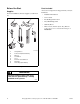
Dimensions 23.5 in. (59.7 cm) 28 in. (71.1 cm) *43 in. (109.2 cm) 15.4 in. (39.1 cm) *15.44 in. (39.2 cm) *4.5 in. (11.4 cm) *36 in. (91.4 cm) 8.0 in. (20.3 cm) *40.25 in. (102.24 cm) 22.38 in. (56.85 cm) 0.4 in. (1.1 cm) *4.0 in. (10.2 cm) 26.9 in. (68.3 cm) DRY2203N ELECTRIC DRYERS DRY2203N * With leveling legs turned into base. 23.5 in. (59.7 cm) 28 in. (71.1 cm) 0.4 in. (1.1 cm) 15.4 in. (39.1 cm) 26.9 in. (68.3 cm) *4.0 in. (10.2 cm) *15.44 in. (39.2 cm) *43 in. (109.2 cm) *4.
Before You Start Parts Included Supplies An accessories bag has been shipped inside your dryer. It includes: For most installations, the basic supplies you will need are: • Installation Instructions • User’s Guide 1 2 • Product Registration Card • Dryer Rack Reply Card • Warranty Bond 4 5 • Three screws (electric dryers only). Refer to Connecting Power Cord sections in Step 4 of Installation.
Installing the Dryer No other fuel burning appliance should be installed in the same closet with the dryer. Step 1: Position and Level the Dryer The dryer must not be installed or stored in an area where it will be exposed to water and/or weather. Install dryer before washer. This allows room for attaching exhaust duct. Select a location with a solid floor. Dryers installed in residential garages must be elevated 18 inches (46 cm) above the floor.
Place the dryer in position, and adjust the legs until the dryer is level from side to side and front to back. The dryer must not rock. WARNING This gas appliance contains or produces a chemical or chemicals which can cause death or serious illness and which are known to the State of California to cause cancer, birth defects, or other reproductive harm.
• Ductwork that runs through unheated areas must be insulated to help reduce condensation and lint build-up on pipe walls. • When exhausting the dryer to the outdoors, the dryer can be installed with “0” inch clearance at sides and rear. Clearance of the duct from combustible construction must be a minimum of 2 inches (5.08 cm). • For proper operation, it is important that the dryer has an ample amount of outside make-up air.
Exhaust System NOTE: Weather hood should be installed at least 12 inches (30.5 cm) above the ground. Larger clearances may be necessary for installations where heavy snowfall can occur. For best drying results, recommended maximum length of exhaust system is shown in Table 1. To prevent backdraft when dryer is not in operation, outer end of exhaust pipe must have a weather hood with hinged dampers (obtain locally). Number of 90° Elbows Weather Hood Type Recommended 4 in. (10.
Step 3: (Gas Dryer Only) Connect Gas Supply Pipe Natural Gas Altitude Adjustments Altitude WARNING To reduce the risk of gas leaks, fire or explosion: • The dryer must be connected to the type of gas as shown on nameplate located in the door recess. • Use a new flexible stainless steel connector. • Use pipe joint compound insoluble in L.P. (Liquefied Petroleum) Gas, or Teflon tape, on all pipe threads. • Purge air and sediment from gas supply line before connecting it to the dryer.
4. Tighten all connections securely. Turn on gas and check all pipe connections (internal & external) for gas leaks with a non-corrosive leak detection fluid. NOTE: The dryer and its appliance main gas valve must be disconnected from the gas supply piping system during any pressure testing of that system at test pressures in excess of 1/2 psi (3.45 kPa). Refer to Step 9 (Check Heat Source). L.P. (Liquefied Petroleum) Gas, 2500 Btu/ft3 (93.1 MJ/m3) service must be supplied at 10 ± 1.
The dryer has its own terminal block that must be connected to a separate branch, 60 Hertz, single phase circuit, AC (alternating current) circuit, fused at 30 Amperes (the circuit must be fused on both sides of the line). Electrical service for the dryer should be of maximum rated voltage (208 or 240 Volt, depending on heating element) listed on the nameplate. Do not connect dryer to 110, 115, or 120 Volt circuit.
Connecting Power Cord with Three-Wire Plug NOTE: Four-wire cord is required for new branchcircuit installations, mobile homes or where codes do not permit grounding through neutral. NOTE: The power cord is NOT supplied with the electric dryer. Type of power cord and gauge of wire must conform to local codes and instructions. POWER SUPPLY POWER SUPPLY 1 The method of wiring the dryer is optional and subject to local code requirements.
4. Use the three screws from the accessories bag to attach the power cord wires to the terminal block. Refer to Figure 9. 1 Connecting Power Cord with Four-Wire Plug NOTE: Four-wire cord is required for new branchcircuit installations, mobile homes or where codes do not permit grounding through neutral. 2 2 1 3 4 12 V. 0 ± A 1 .C 2 . 3 12 V. 0 ± A 1 .C 2 . D286I 240 ± 12 V.A.C. “L1” Terminal Neutral Terminal “L2” Terminal 12 V. 0 ± A 1 .C 2 . 0 V.A.C. 12 V. 0 ± A 1 .C 2 . 1 2 3 Figure 9 5.
3. Remove ground screw and save for use in Step 5. Remove wire and use in Step 6. 5. Attach power cord ground (green) wire to rear bulkhead using ground screw removed in Step 3. 1 1 7 6 5 D697I 2 4 D697I 1 Ground Screw 3 DRY1920N Figure 12 DRY1920N 4. Use a strain relief and insert end of power cord through power supply hole. 1 2 3 4 5 6 7 White “L2” Terminal Black Green Red Neutral Terminal “L1” Terminal Figure 14 6.
Step 5: Reverse Door, if Desired The door on this dryer is completely reversible. To reverse door proceed as follows: 5. Remove door strike from door liner and reinstall on opposite side. 1. Remove four hinge attaching screws. DRY1917N DRY1917N 6. Insert liner under flange on bottom of door, then push top of door liner into place. D675I D675I 2. Remove all nine screws. B A DRY1918N DRY1918N 7. Reinstall nine screws removed in Step 2. D272P 3.
9. Reinstall four hinge attaching screws, removed in Step 1. Gas Dryer Dryer requires 120 Volt, 60 Hertz electrical supply and comes equipped with a 3-prong grounding plug. Refer to serial plate for specific electrical requirements. NOTE: The wiring diagram is located inside the control hood.
Grounding Information The dryer must be grounded. In the event of malfunction or breakdown, grounding will reduce the risk of electric shock by providing a path of least resistance for electric current. The dryer is equipped with a cord having an equipment-grounding conductor and a 3 prong grounding plug. The three-prong grounding plug on the power cord should be plugged directly into a polarized three-slot effectively grounded receptacle rated 110/120 Volts AC (alternating current) 15 Amps.
Gas Dryers 1. Loosen the air shutter lockscrew. To view the burner flame, remove the lower front panel of the dryer. 2. Turn the air shutter to the left to get a luminous yellow-tipped flame, then turn it back slowly to the right to obtain a steady, soft blue flame. Close the loading door, start the dryer in a heat setting (refer to the Operating Instructions supplied with the dryer); the dryer will start, the igniter will glow red and the main burner will ignite. 3.
Installer Checklist Fast Track for Installing the Dryer (Refer to the manual for more detailed information) 1 6 • Position and Level the Dryer. • Wipe Out Inside of Dryer. LEVEL D255I D255I D256I 2 D618I D618I CHECK D259I CHECK 7 • Connect Dryer Exhaust System. • Plug In the Dryer. Gas Electric CHECK DRY1915N DRY1915N CHECK 3 GAS ONLY • Connect Gas Supply Pipe. • Check for Gas Leaks. 8 D258I CHECK • Recheck Steps 1-7. • Check Heat Source. ELECTRIC ONLY • Connect Electrical Cord.