
Operating instructions

M413620
61
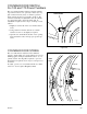
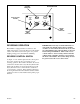
BELT DRIVE
Reversing Models (see
Figure 32
)
Proper tension is when the drive belt can be depressed
approximately 1/2 inch (1.27 cm) by applying light
thumb pressure (approximately 5 pounds) at a point
midway between the sheave and motor pulley.
Proper tension is when each cylinder belt can be
depressed approximately 3/16 inch (.48 cm) by applying
light thumb pressure (approximately 5 pounds) at a point
midway between the sheave and the idler.
1. Remove guard from rear of tumbler.
2. To adjust cylinder belt tension, loosen idler housing
bolts holding idler housing assembly to the housing
support.
3. Position housing assembly by turning adjusting bolt
until proper belt tension is reached, then retighten
idler housing bolts.
NOTE: Adjusting the cylinder belt tension will
change the drive belt tension. Drive belt tension must
also be adjusted.
4. Loosen the locking bolt.
5. Loosen the adjusting nut and use the adjusting screw
to move the motor up or down.
6. Once proper belt tension is reached, retighten the
adjusting nut and locking bolt.
7. Replace the guard on rear of tumbler.
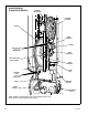
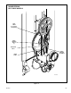
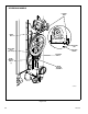
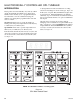
BELT DRIVE
120 and 170 Pound Reversing Models (see
Figures 25 & 26
)
The drive assemblies consist of motors, belts, eyebolts,
and a step pulley.
The pulley diameters are sized to produce a cylinder
speed of 37-39 RPMS (120 lb.) or 29-31 RPMS (170 lb.).
The step pulley assembly is used for speed reduction as
well as a means of adjusting belt tension. The pulley
mounting plate is attached to the frame of the cabinet.
The frame mounting plate has vertically slotted holes
allowing up and down movement of the step pulley
mounting plate for belt adjustment.
Adjust the belt tension as follows:
1. Disconnect electrical power to the tumbler before
attempting any adjustments to the drive assemby.
2. Loosen the upper nut on the final drive eye-bolt
(Figures 25 & 26).
3. Rotate the lower nut of the final drive eye-bolt
clockwise until proper belt tension is achieved.
4. Rotate upper nut clockwise against the lower nut in
order to lock it into place.
5. If necessary, adjust the drive motor belt tension eye-
bolt using the same procedure as steps 1-4. (Figures
25 & 26).
6. Adjust blower belt tension on 120 pound 50 Hz.
tumblers and all 170 pound tumblers using the same
procedure as in steps 1-4.
NOTE: Proper tension for new belts is 45-55 pounds
for the motor belt and 55-65 pounds for the final
drive, measured with a Borroughs Belt Tension
Gauge. Using a Browning Belt Tension Gauge, the
motor belt deflection should be 5/16 inch at five
pounds pressure, and final drive belt deflection
should be 1/4 inch at five pounds pressure.
Belts should not slip or make any noise when starting up
under normal load.
To reduce the risk of serious injury or
death, disconnect power to the tumbler
before performing this operation.
W074
WARNING
To reduce the risk of serious injury or
death, guard panel MUST be installed on
the rear of the tumbler after the belt
adjustment is made.
W075
WARNING