INSTALLATION INSTRUCTIONS A80UH2V & 80G1UH2V Warm Air Gas Furnace Upflow / Horizontal Left and Right Air Discharge This manual must be left with the homeowner for future reference. This is a safety alert symbol and should never be ignored. When you see this symbol on labels or in manuals, be alert to the potential for personal injury or death. WARNING CAUTION Improper installation, adjustment, alteration, service or maintenance can cause property damage, personal injury or loss of life.
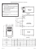
A80UH2V & 80G1UH2V Unit Dimensions - inches (mm) NOTE - 20C and 20D size units installed in upflow applications that require air volumes of 1800 cfm (850 L/s or greater must have one of the following: 1. Return air from single side transition will accommodate 20 x 25 x 1 in. (508 x 635 x 25 mm) cleanable air filter. (Required to maintain proper air velocity.) 2. Single side return air with optional RAB Return Air Base 3. Return Air from bottom and one side. 4. Return air from both sides. 5.
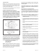
EXPLODED VIEW HEAT EXCHANGER COMBUSTION AIR INDUCER COMBUSTION AIR INDUCER PRESSURE SWITCH ROLLOUT SWITCH GAS VALVE BURNER BOX CABINET CONTROL BOX ACCESS PANEL BLOWER ASSEMBLY Figure 1 506471-01 Issue 1034 Page 3 of 41
A80UH2V & 80G1UH2V Gas Furnace The A80UH2V & 80G1UH2V gas furnace is shipped with ready for installation in the upflow or horizontal position (left or right). for horizontal left position the combustion air pressure switch must be moved). The furnace is shipped with the bottom panel in place. The bottom panel must be removed if the unit is to be installed in a horizontal application. The panel may also be removed in upflow applications. The furnace is equipped for installation in natural gas applications.
Temperature Rise NOTE: Furnace must be adjusted to obtain a temperature rise within the range specified on the unit nameplate. Failure to do so may cause erratic limit operation and may result in premature heat exchanger failure. This furnace must be installed so that its electrical components are protected from water.
General These instructions are intended as a general guide and do not supersede local codes in any way. Consult authorities having jurisdiction before installation. In addition to the requirements outlined previously, the following general recommendations must be considered when installing one of these furnaces: • • • • Place the furnace as close to the center of the air distribution system as possible. The furnace should also be located close to the chimney or vent termination point.
All gas fired appliances require air for the combustion process. If sufficient combustion air is not available, the furnace or other appliances will operate inefficiently and unsafely. Enough air must be provided to meet the needs of all fuel burning appliances and appliances such as exhaust fans which force air out of the house. When fireplaces, exhaust fans, or clothes dryers are used at the same time as the furnace, much more air is necessary to ensure proper combustion and to prevent a downdraft.
When ducts are used, they shall be of the same cross sectional area as the free area of the openings to which they connect. The minimum dimension of rectangular air ducts shall be no less than 3 inches (75 mm). In calculating free area, the blocking effect of louvers, grilles, or screens must be considered.
Setting Equipment Upflow Applications Allow for clearances to combustible materials as indicated on the unit nameplate. Minimum clearances for closet or alcove installations are shown in Figure 8. WARNING Do not install the furnace on its front or its back. Do not connect the return air ducts to the back of the furnace. Doing so will adversely affect the operation of the safety control devices, which could result in personal injury or death.
Return Air - Upflow Applications Return air can be brought in through the bottom or either side of the furnace installed in an upflow application. If the furnace is installed on a platform with bottom return, make an airtight seal between the bottom of the furnace and the platform to ensure that the furnace operates properly and safely. The furnace is equipped with a removable bottom panel to facilitate installation.
Removing the Bottom Panel Remove the two screws that secure the bottom cap to the furnace. Pivot the bottom cap down to release the bottom panel. Once the bottom panel has been removed, reinstall the bottom cap. See Figure 11. Removing the Bottom Panel Horizontal Applications The furnace can be installed in horizontal applications. Order horizontal suspension kit (51W10) from Allied Air, or use equivalent suspension method. Allow for clearances to combustible materials as indicated on the unit nameplate.
Horizontal Application Unit installed on Platform Table 1 Duct System Use industry approved standards (such as those published by Air Conditioning Contractors of America or American Society of Heating, Refrigerating and Air Conditioning Engineers) to size and install the supply and return air duct system. This will result in a quiet and low static system that has uniform air distribution. Figure 14 NOTE: Do not operate the furnace in the heating mode with an external static pressure that exceeds 0.
Venting A 4 inch diameter flue transition is factory installed on the combustion air inducer outlet of all models. Figure 16 shows the combustion air inducer as shipped from the factory. Mounting Screws Location If necessary reposition the combustion air inducer, pressure switch and/or make-up box as needed per the following steps. See Figures 16 through 22. 1. Remove the four mounting screws (Figure 15) which secure the combustion air inducer / pressure switch assembly to the orifice plate.
Horizontal Position HORIZONTAL LEFT POSITION Top Vent discharge • • HORIZONTAL RIGHT POSITION Top Vent Discharge Disconnect pressure switch hose from barbed fitting on the pressure switch assembly. Remove pressure switch assembly (1 screw) and cut wire tie to free pressure switch wires. Reinstall pressure switch on the other side of orifice plate and reconnect pressure switch hose.
These series units are classified as fan assisted Category I furnaces when vertically vented according to the latest edition of National Fuel Gas Code (NFPA 54 / ANSI Z223.1) in the USA. A fan assisted Category I furnace is an appliance equipped with an integral mechanical means to either draw or force combustion products through the combustion chamber and/or heat exchanger. This unit is not approved for use with horizontal venting. NOTE: Use these instructions as a guide. They do not supersede local codes.
Common Venting Using Tile Lined Interior Masonry Chimney and Combined Vent Connector NOTE: Refer to provided venting tables for installations. NOTE: The chimney must be properly sized per provided venting tables or lined with listed metal lining system. Figure 25 DO NOT insulate the space between the liner and the chimney wall with puffed mica or any other loose granular insulating material. Never connect a Category I appliance to a chimney that is servicing a solid fuel appliance.
6. The entire length of single wall metal vent connector shall be readily accessible for inspection, cleaning, and replacement. 7. Single appliance venting configurations with zero lateral lengths (Tables 3 and 4) are assumed to have no elbows in the vent system. For all other vent configurations, the vent system is assumed to have two 90° elbows.
Capacity of Type B Double Wall Vents with Type B Double Wall Connectors Serving a Single Category I Appliance NOTE: Single appliance venting configureations with zero lateral lengths are assumed to have no elbows in the vent system. For all other vent configurations, the vent system is assumed to have two 90 ° elbows. For each additional 90° elbow or equivalent (for example two 45° elbows equal one 90° elbow) beyond two, the maximum capacity listed in the venting table should be reduced by 10 percent (0.
Capacity of Type B Double Wall Vents with Single Wall Metal Connectors Serving a Single Category I Appliance NOTE: Single appliance venting configureations with zero lateral lengths are assumed to have no elbows in the vent system. For all other vent configurations, the vent system is assumed to have two 90 ° elbows. For each additional 90° elbow or equivalent (for example two 45° elbows equal one 90° elbow) beyond two, the maximum capacity listed in the venting table should be reduced by 10 percent (0.
Vent Connector Capacity Type B Double Wall Vents with Type B Double Wall Connectors Serving Two or More Category I Appliances Table 5 Common Vent Capacity Type B Double Wall Vents with Type B Double Wall Connectors Serving Two or More Category I Appliances Table 6 Page 20 of 41 Issue 1034 506471-01
Vent Connector Capacity Type B Double Wall Vents with Single Wall Metal Connectors Serving Two or More Category I Appliances NOTE: Single appliance venting configureations with zero lateral lengths are assumed to have no elbows in the vent system. For all other vent configurations, the vent system is assumed to have two 90 ° elbows.
Removal of the Furnace from Common Vent In the event that an existing furnace is removed from a venting system commonly run with separate gas appliances, the venting system is likely to be too large to properly vent the remaining attached appliances. Conduct the following test while each appliance is operating and the other appliances (which are not operating) remain connected to the common venting system.
Gas Piping CAUTION If a flexible gas connector is required or allowed by the authority that has jurisdiction, black iron pipe shall be installed at the gas valve and extend outside the furnace cabinet. The flexible connector can then be added between the black iron pipe and the gas supply line. Gas Supply 1. This unit is shipped standard for left or right side installation of gas piping (or top entry in horizontal applica-tions). Connect the gas supply to the piping assembly. 2.
NOTE: BLACK IRON PIPE ONLY TO BE ROUTED INSIDE OF CABINET Figure 26 Horizontal Applications Possible Gas Piping Configurations NOTE: BLACK IRON PIPE ONLY TO BE ROUTED INSIDE OF CABINET Figure 27 Page 24 of 41 Issue 1034 506471-01
Leak Check After gas piping is completed, carefully check all piping connections (factory and field installed) for gas leaks. Use a leak detecting solution or other preferred means. NOTE: If emergency shutoff is necessary, shut off the main manual gas valve and disconnect the main power to the furnace. The installer should properly label these devices. The unit is equipped with a field make-up box on the left hand side of the cabinet.
Table 10 4. Before connecting the thermostat, check to make sure the wires will be long enough for servicing at a later date. Make sure that thermostat wire is long enough to facilitate future removal of blower for service. 5. Complete the wiring connections to the equipment. Use the provided unit wiring diagram and the field wiring diagram shown in Figure 41. Use 18 gauge wire or larger that is suitable for Class II rating for thermostat connections. 6.
In all instances, other than wiring for the thermostat, the wiring to be done and any replacement of wire shall conform with the temperature limitation for Type T wire –63°F (35°C) rise. Automatic Heat Staging Jumper Connect a sufficiently sized wire with ground to the furnace’s line voltage connections and ground lug. Refer to the furnace rating plate for electrical characteristics to be used in sizing field supply wiring and overcurrent protection.
Active Dehumidification To achieve additional dehumidification, clip the jumper wire located below the DEHUM terminal on the integrated ignition/ blower control board and connect a humidity control that opens on humidity rise to the DEHUM and R terminals. The DEHUM terminal on the control board must be connected to the normally closed contact of the humidity control so that the board senses an open circuit on high humidity.
ADJUSTING AIRFLOW Table 11 506471-01 Issue 1034 Page 29 of 41
START-UP To Start Furnace: Lighting Instructions CAUTION For Your Safety, Read Before Operating Be sure the manual gas control has been in the “OFF” position for at least 5 minutes before starting the unit. Do not attempt to manually light the burners. WARNING If you do not follow these instructions exactly, a fire or explosion may result causing property damage, personal injury, or loss of life. 1. Set the room thermostat to lowest setting. 2. Remove burner access door.
OPERATION the R to G circuit and the circulating blower motor runs at 50% of the selected cooling CFM until switched off. When the call for fan is turned off, the control de-energizes the circulating blower. Sequence of Operation (see Figures 33 – 37) Heating On a call for heat from the room thermostat, the control board performs a 1 second self check. Upon confirmation that the pressure switch contacts are in an open position, the control energizes the combustion blower on high speed.
1st Stage - 2nd Stage (W1/W2) Heat Call W1/W2 w1 w2 W1 1 min 1 min 100%* 75%* 100%** 2 min 2 min W1 - Heat Demand Present w1 - Heat Demand Satisfied 82%** 82%* W2 - High Heat Demand Present w2 - High Heat Demand Satisfied w1 50%* CALL * Percentage of Low Fire CFM OFF ** Percentage of High Fire CFM Figure 33 Single Stage Cooling High Heat (W2) Call W2 y Y w2 7.
Controls Following is a description of the operation of some of the controls used in this furnace. All models use one of each control, except as noted. Pressure Switch The pressure switch is a normally open switch that monitors combustion air flow. Inadequate air flow resulting from excessive venting system restriction or a failed combustion blower will cause the switch to remain open. A80UH2V and 80G2UHV models have two pressure switches. propane gas, the manifold pressures are 4.9" w.c.
For Natural Gas: Check the furnace rate by observing the gas meter, when available, making sure all other gas appliances are turned off. The test hand on the meter should be timed for at least one revolution. Note the number of seconds for one revolution. BTU/HR Cubic Feet Per Revolution x 3600 x Heating = INPUT # Seconds Per Revolution Value The heating value of the gas can be obtained from the local utility company.
MAINTENANCE Typical Flame Appearance WARNING Heat Exchanger ELECTRICAL SHOCK, FIRE, OR EXPLOSION HAZARD Burner Failure to follow the safety warnings exactly could result in dangerous operation, serious injury, death, or property damage. Gas Manifold Improper servicing could result in dangerous operation, serious injury, death, or property damage. Burner Flame (Blue Only) • Before servicing, disconnect all electrical power to furnace.
CONTROL DIAGNOSTICS Failure Codes - Red LED Troubleshooting Make the following visual checks before troubleshooting: 1. 2. Check to see that the power to the furnace and the integrated ignition/blower control board is ON. The manual shutoff valves in the gas line to the furnace must be open. 3. Make sure all wiring connections are secure. 4. Review the Sequence of Operation (see page 31). Start the system by setting thermostat above room temperature. Observe system response.
REPAIR PARTS The following repair parts are available from the local distributor. When ordering parts, include the complete furnace model number and serial number which are printed on the rating plate located on the furnace.
Wiring Diagram VLT WHT RED BLK BRN BRN FLAME SENSOR ROLLOUT SWITCH GAS VALVE VLT VLT IGNITER M C HI WHT/BLK MAIN LIMIT 1 2 2-PIN 1 2 CONNECTOR RED RED/BLK ORN BLU GRY BRN S1 3 2 1 P1 3 2 1 VLT INTERLOCK SWITCH WHT BLK HOT NEUTRAL 120/1/60 GROUND GRN PRESSURE PRESSURE PRESSURE SWITCH - ROLLOUT SWITCH SWITCH SWITCH DRAIN (HIGH) (LOW) (IF USED) (IF USED) YEL YEL BLK WHT INDUCED DRAFT BLOWER 5-PIN CONNECTOR 24V TRANSFORMER AUX LIMIT SWITCH (IF USED) LO HEAT GRY BRN WHT/BLK VLT PARK
Typical Field Wiring Diagram Figure 41 506471-01 Issue 1034 Page 39 of 41
START-UP & PERFORMANCE CHECK LIST UNIT SET UP Page 40 of 41 Issue 1034 506471-01
UNIT OPERATION 506471-01 Issue 1034 Page 41 of 41