Installation Manual CopperJet CopperJet CopperJet CopperJet CopperJet CopperJet 810 811 820 821 822 823 Based on firmware 5.
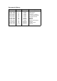
Document History Date 21 Mar 2003 21 Mar 2003 31 Mar 2003 2 Apr 2003 4 Apr 2003 7 Apr 2003 22 Apr 2003 23 Apr 2003 29 Apr 2003 17 Jul 2003 03 Nov 2003 04 Nov 2003 Version 1 1 1.1 1.2 1.3 1.4 1.5 1.6 1.7 1.8 1.9 1.10 Status Draft Draft Draft Draft Draft Draft Draft Release Draft Release Release Release Description Initial version Initial version First check Comment + history 2nd Check and layout Changed pictures Updated Updated Headers and footers Updated Firmware 5.
Product DISCLAIMER This manual by ALLIED DATA TECHNOLOGIES B.V. (hereafter referred to as ALLIED DATA TECHNOLOGIES) is a reflection of the current state of the products described in it. It has been our goal to provide a manual that is complete and clear to ensure that our products are as easy to use. However, this manual may contain technical inaccuracies and typing errors.
Contents 1 Packaging contents ...............................................................................4 2 LED Indicators and back panel ................................................................5 2.1 2.2 2.3 2.4 2.5 3 Connecting the CopperJet.......................................................................8 3.1 3.2 4 Connecting the CopperJet 81x .........................................................8 Connecting the CopperJet 82x ..................................................
6.1 6.2 Upgrading and downgrading firmware............................................. 41 Uploading and retrieving configuration profile .................................. 41 7 CopperJet Revisions ............................................................................ 42 8 Glossary ............................................................................................
Chapter 1: Packaging contents 1 Packaging contents The packaging should contain the following parts: All CopperJets CopperJet 81x only CopperJet 82x only CopperJet 81x/82x with USB connector only Caution! To prevent overheating, make sure that the CopperJet has enough free space on both sides and above to permit free airflow.
Chapter 2: LED Indicators and back panel 2 LED Indicators and back panel Before you begin with the installation, please take a moment to become more familiar with the LED indicators and back panel of the CopperJet. 2.1 CopperJet 81x LED indicators ACT: Blinks when data traffic is generated. ADSL: Blinking indicates that the DSL protocols starts handshaking. Illuminates when the ADSL network is correctly configured and connected.
Chapter 2: LED Indicators and back panel 2.3 CopperJet 82x LED indicators Power: When the CopperJet is connected to a power source, the Power LED will illuminate. ADSL: Blinking indicates that the DSL protocols starts handshaking. Illuminates when the ADSL network is correctly configured and connected. USB: The USB led will illuminate when you connect the CopperJet to the USB port on your PC, and the USB drivers are installed. Note: not available on all units.
Chapter 2: LED Indicators and back panel default configuration is restored. The softkey can be released and the CopperJet will restart automatically with the default configuration. Important: Never disconnect the power from the modem while the softkey is pressed.
Chapter 3: Connecting the CopperJet 3 Connecting the CopperJet To connect the CopperJet to the computer, you must have installed an Ethernet 10Base-T card in your computer. You need to have a static IP address on your network card that is in the same subnet as the web interface IP address of the CopperJet. The default web interface IP address for Ethernet is 172.19.3.1. For USB, the default IP address is 172.20.3.1.
Chapter 4: Before you start 4 Before you start The following information may be required for configuring the CopperJet. If you do not know if all the information is needed, please contact your DSL service provider before proceeding with the configuration. 4.1 IP Address Settings The CopperJet allows the ISP to dynamically assign IP Address settings. If your ISP requires static setting of specific IP address information, you need to receive the following information: • • • 4.
Chapter 5: Configuring the CopperJet 5 Configuring the CopperJet Configuration of the CopperJet ADSL router can be done through the build-in HTTP WebServer. Users can access this WebServer using a standard browser like Netscape Navigator or Microsoft Internet Explorer. 5.1 Accessing the build-in WebServer To access the build-in WebServer, you need to launch a HTTP Web browser. Enter the IP address of the CopperJet in the address bar. The default Ethernet IP address of the CopperJet is: 172.19.3.
Chapter 5: Configuring the CopperJet 5.1.1 Logging in to the WebServer The first time that you click on an entry from the left-hand menu to display a page, a login box is displayed. You must enter your username and password to access the pages. The default network login is: Username: admin Password: admin Click on OK. You can now configure your CopperJet using the WebServer. 5.1.
Chapter 5: Configuring the CopperJet 5.2 Quickstart With the Quickstart option you can configure your CopperJet in only a few steps. The number of steps is depending on the specific ISP network. To use the Quickstart, click on Quickstart (on the left hand side). The Quickstart page is displayed. Select your ISP network from the dropdown-list and click on OK. Some settings may already been pre-configured. This is shown at the top op the page Predefined Settings.
Chapter 5: Configuring the CopperJet 5.3 LAN Connections LAN Connections allows you to add, configure and remove the Ethernet and/or USB connections. It is also used to assign IP addresses to these connections. The Ethernet connection CANNOT be removed only edited. Go to the Configuration menu and click on LAN connections. The LAN Connections page is displayed. This page displays a table that lists all existing LAN connections.
Chapter 5: Configuring the CopperJet 5.3.3 Edit a LAN connection To update or edit your LAN IP address, click on the Edit hyperlink of the LAN connection you want to update or edit. The Default LAN Port page is displayed.
Chapter 5: Configuring the CopperJet 5.3.4 Configuring DHCP Server DHCP allows you to dynamically assign IP address to the computers connected to the Ethernet or USB interface of the CopperJet. The CopperJet allows multiple DHCP Servers for multiple IP subnets. Usually, you would only require 1 DHCP Server. This option allows you to enable, disable and configure the DHCP server on your CopperJet. By default, the DHCP Server is disabled. 5.3.4.
Chapter 5: Configuring the CopperJet Select DHCP Server en click on Configure. The DHCP Subnet page is displayed. This page allows you to: • Set the subnet for the DHCP Server manually OR use the same subnet used on the IP interface by selecting Use Subnet of IP interface. • Set the DHCP address range manually OR use a default range of 253 addresses by selecting Use Default Range. • Set the default and maximum lease times for this DHCP Server.
Chapter 5: Configuring the CopperJet If you want to carry out further configuration of your DHCP Server, click on the Advanced Options page at the bottom of the DHCP configuration page. The Edit DHCP Server page is displayed. This page allows you to edit the options that appear on the DHCP Server page. Default lease time: If the client that requests the lease, does not ask for a specific expiry time (43200) the default time (in seconds) will be assigned to a lease.
Chapter 5: Configuring the CopperJet 5.3.4.2 Disabling DHCP Server To disable the DHCP Server, go to the Configuration menu and select DHCP server. The DHCP Server page is displayed. Select Disabled and click on Configure to disable the DHCP Server. The DHCP: disable server and relay agent page is displayed. At the bottom of the page, click on Apply. The DHCP Server page is displayed to ensure that the DHCP Server is disabled.
Chapter 5: Configuring the CopperJet 5.3.5 Configuring DNS Relay DNS Relay allows you to send DNS requests to the CopperJet instead of the DNS servers at the service provider. The CopperJet relays these requests to specified DNS Servers. The DNS servers can be discovered automatically through DHCP on the WAN interface OR configured manually. 5.3.5.1 Enabling DNS Relay manually To manually enable and configure DNS Relay, go to the Configuration menu and select DNS relay.
Chapter 5: Configuring the CopperJet The DNS relay is enabled. Relaying to following DNS servers:212.213.214.215 When finished configuring DNS Relay, go to the Configuration menu and click on Save config to save the new settings into the CopperJet. Note: You need to fill in the CopperJet IP address as DNS server on your network card or configure the DHCP Server and enable the setting: Use Router as DNS Server. 5.3.5.
Chapter 5: Configuring the CopperJet For PPPoA, select the PPP tab. For PPPoE, select the PPPoE tab. Be sure that following options are set to true if you want the CopperJet to automatically discover the DNS addresses. When you are finished with configuring DNS Relay for the WAN connection, click on Apply. Go to the Configuration menu and click on Save config to save the new settings into the CopperJet.
Chapter 5: Configuring the CopperJet 5.4 WAN Connections To create a DSL Connection, you need to add a WAN connection. Depending on the network of your ISP, you need to configure either a BRIDGED or ROUTED WAN connection. Bridged connections are often RFC1483 BRIDGED (attached to the Bridge). Routed connections are often RFC1483 ROUTED, PPPoE, PPPoA or IPoA (attached to the Router). To create and configure WAN connections for your CopperJet, go to the Configuration menu and click on WAN connections.
Chapter 5: Configuring the CopperJet 5.4.1 Configuring RFC1483 Bridged One of the most commonly used connections is RFC 1483 Bridged, attached to the Bridge. This WAN connection performs a transparent bridge between the ADSL connection and the LAN connection. The CopperJet does not route any packets. All packets received on one interface (i.e. ADSL) are transparently bridged to the other interface (i.e. Ethernet).
Chapter 5: Configuring the CopperJet After configuring the CopperJet in RFC1483 Bridge mode, you may need to configure your DHCP settings on your local network card. DHCP, which stands for Dynamic Host Configuration Protocol, automatically allocates an IP address on your local networkcard. 5.4.1.1 Configuring DHCP on your networkcard To configure DHCP on a networkcard for a Windows PC, follow the steps below. 1. Click the Start menu. 2. Click Settings -> Control panel. 3.
Chapter 5: Configuring the CopperJet 5.4.2 Configuring RFC1483 Routed A RFC 1483 Routed connection is used when your Service Provider delivers a routed connection between the CopperJet and the Service Provider Network. You need to add detailed configuration information about the WAN service that you are creating. This information must be provided by your service provider. Description: RFC1483, this is the default WAN connection name. VPI: Virtual Path Identifier. A field in the ATM header.
Chapter 5: Configuring the CopperJet Default Gateway: When you use the option WAN IP address, you must fill in the default gateway. Enable NAT: NAT is by default enabled. When finished configuring the WAN connection, click on OK. Go to the Configuration menu and click on Save config to save the new settings into the CopperJet.
Chapter 5: Configuring the CopperJet 5.4.3 Configuring PPPoA routed PPPoA routed is mostly used when your Service Provider has an ATM network which requires authentication (username and password). You need to add detailed configuration information about the WAN service that you are creating. This information must be provided by your service provider. Description: PPPoA, this is the default WAN connection name. VPI: Virtual Path Identifier. A field in the ATM header.
Chapter 5: Configuring the CopperJet PAP: Password Authentication Protocol. The server sends an authentication request to the remote user that is dialling in. PAP passes the unencrypted username and password and identifies the remote end. CHAP: Challenge Handshake Authentication Protocol The server sends an authentication request to the remote user that is dialling in. CHAP passes the encrypted username and password and identifies the remote end.
Chapter 5: Configuring the CopperJet 5.4.4 Configuring PPPoE routed PPPoE routed is mostly used when your Service Provider has an Ethernet network which requires authentication (username and password). You need to add detailed configuration information about the WAN service that you are creating. Your service provider must provide this information. Description: PPPoE, this is the default WAN connection name. VPI: Virtual Path Identifier. A field in the ATM header.
Chapter 5: Configuring the CopperJet Encapsulation: LLC/SNAP by default. Access concentrator: Some service provider requires this entry. If the service provider does not provide this, leave it blank. Service name: Some service provider requires this entry. If the service provider does not provide this, leave it blank. Authentication: Choose the authentication method provided by your service provider. None: You don’t need to set any authentication.
Chapter 5: Configuring the CopperJet Auto-configure DHCP server:By default Disabled. When enabled, your Service Provider is able to provide the DHCP Server IP range dynamically based on the subnetmask. This functionality is also known as learning DHCP Server. Default DHCP server range size: Number of IP addresses that are used for the DHCP server. Default is 4. Enable NAT: NAT is by default enabled. When finished configuring the WAN connection, click on OK.
Chapter 5: Configuring the CopperJet 5.5 DSL Line The DSL Port menu allows you to configure specific DSL settings. Usually, the default settings are sufficient to make a good DSL connection. Only for finetuning or advanced administration, the DSL port menu brings useful information. From the Configuration menu, go to Ports and click on DSL. The DSL Port Configuration page is displayed. This page provides the following information. Connected: Shows if your DSL line is up (true) or not (false).
Chapter 5: Configuring the CopperJet 5.6 Security The CopperJet has extensive Security functionality like a Stateful Inspection Firewall, Network Address Translation (NAT) and Filters. One of the most used functionality is NAT.
Chapter 5: Configuring the CopperJet You must enable Security before you can add security functionality like Firewall, NAT or filters. In the Security State section: Click on the Security Enabled radio button and select Change State to update the Security State section. The overall Security is now enabled. 5.6.2 Configuring Security Interfaces Before Security options can be configured, there must be at least 2 Security interfaces defined and configured.
Chapter 5: Configuring the CopperJet The Security Interface Configuration page is displayed and the security interface is added to the section Security Interface. 5.6.3 Configuring Network Address Translation (NAT) The Network Address Translator (NAT) implements Port Address Translation (PAT) and provides Network Address Port Translation (NAPT), also known as IP Masquerading.
Chapter 5: Configuring the CopperJet On this page NAT can be enabled or disabled. Nat Enabled: false NAT is disabled true NAT is enabled After you changed the setting, click on Apply. Don’t forget to save the changes. Go to the Configuration menu and click on Save config to save the new settings into the CopperJet. 5.6.3.1 Configuring NAT reserved mapping Reserved mapping allows you to map an outside security interface or an IP address from a global pool to an individual IP address inside the network.
Chapter 5: Configuring the CopperJet This page allows you to configure your reserved mapping. Add specific values for the following table entries. Global IP Address: If you are mapping from a global IP address, type the address here. If you are mapping from a security interface, type 0.0.0.0. Internal IP Address: The IP address of an individual host inside your network. Transport Type: Specify the transport type that you want to map from the outside interface to the inside.
Chapter 5: Configuring the CopperJet Important: Enabling the Firewall will block ALL traffic going in and out of the CopperJet. Firewall Policies need to be configured for allowing traffic to pass through. 5.6.5 Enabling Intrusion Detection Before enabling Intrusion Detection, you must have Security enabled and you must have at least 1 internal interface or 1 external interface configured. Be sure that the WAN and/or LAN connections and the Security Interfaces are defined and configured.
Chapter 5: Configuring the CopperJet A list of options is displayed for configuring the Trigger. Allow Multiple Hosts: Select allow if you want a secondary session to be initiated to/from different remote hosts. Select block if you want a secondary session to be initiated only to/from the same remote host. Default allow. Max Activity Interval: Type the maximum interval time (in milliseconds) between the use of secondary port sessions. Default 10000.
Chapter 5: Configuring the CopperJet The Firewall Trigger Configuration page is displayed and details of the deleted trigger have been removed.
Chapter 6: Firmware and configuration management 6 Firmware and configuration management The CopperJet has both a firmware and configuration file stored in its flash memory. These files cannot be accessed through the WebServer interface. Use the CopperJet Monitor Tool v3.4.5 or newer to access the firmware and configuration profile. Important: do NOT use the CopperJet Configurator or CopperJet Monitor v2.xx for firmware 5.xx. 6.
Chapter 7: CopperJet Revisions 7 CopperJet Revisions There are currently 4 different revisions of the CopperJet 81x and 82x products available i.e. revision 1 (r1), revision 2 (r2), revision 3 (r3) and revision 4 (r4). Important: You need to know what the revision number is of a CopperJet to be able to upgrade new firmware and profiles (configurations).
Chapter 8: Glossary 8 Glossary ADSL Strictly speaking, Asymmetric Digital Subscriber Line defines only a way of transmitting broadband data (at speeds between 64kbps and 8Mbps) between a user’s premises (home or office) and the local telephone exchange. In order to increase the number of customers that it is possible to serve, the upstream speed (from the user) is lower than the downstream speed (to the user), so the service is ‘asymmetric’.
Chapter 8: Glossary encapsulation used to carry the TCP/IP traffic over the ATM connection and pass the data into the ISPs normal network. In addition, if PPP is one of the encapsulating protocols, the BAS performs the user authentication (perhaps using an authentication server such as RADIUS to verify the username/password combination).
Chapter 8: Glossary Analogy: Inter-office mail may be consolidated into a single envelope to save postage charges. But if individual documents are placed directly into one big envelope then the receiving post room will not be able to deliver them to the correct place. So, you place each document into its own ‘internal’ envelope before placing all the ‘internal’ envelopes inside the big one.
Chapter 8: Glossary Micro-filter A filter designed to be connected between the ADSL line and every phone that is connected to the line. PPP The protocol used to carry TCP/IP traffic to the ISP across modem and ISDN links. PPP incorporates authentication (username/password checking). Because of its historical use for modem and ISDN users, ISPs favour the use of PPP as an encapsulating protocol for ADSL users.
Chapter 8: Glossary Synchronisation and Training This is the modem initialisation process defined by the G.994.1 (G.hs handshaking) recommendation. This process, if successful, ends in the state known as ‘showtime’. VPI/VCI The ATM Virtual Path Identifier (VPI) and Virtual Channel Identifier (VCI) uniquely identify a data path on an ATM link.