AVT Cameras Hardware Installation Guide V2.0.
Legal notice For customers in the U.S.A. This equipment has been tested and found to comply with the limits for a Class B digital device, pursuant to Part 15 of the FCC Rules. These limits are designed to provide reasonable protection against harmful interference when the equipment is operated in a residential environment.
Contents Contacting Allied Vision Technologies ................................................... 5 Introduction ............................................................................................................ 6 Document history .......................................................................................................... 6 Manual overview............................................................................................................ 6 Conventions used in this manual....
Camera interfaces .............................................................................................32 IEEE 1394a port pin assignment (DOLPHIN, OSCAR, MARLIN, GUPPY)................................................................................. 35 Board level camera: IEEE 1394a port pin assignment ..................................................... 36 IEEE 1394b port pin assignment (PIKE, STINGRAY) ...............................................................................................
Contacting Allied Vision Technologies Contacting Allied Vision Technologies Info • Technical information: support@alliedvisiontec.com phone (for Germany): +49 (0)36428 677-270 phone (for USA): +1 978-225-2030 outside Germany/USA: Please check the link for your local dealer. http://www.alliedvisiontec.com/partner.html • Ordering and commercial information: customer-care@alliedvisiontec.
Introduction Introduction This Hardware Installation Guide describes the hardware installation procedures for all 1394 AVT cameras (Dolphin, Oscar, Marlin, Guppy, Pike, Stingray). The Hardware Installation Guide answers questions about putting AVT cameras into operation, about safety warnings, pin assignments on I/O connectors and 1394a/b connectors.
Introduction • • • – Follow all safety instructions, especially the cautions when connecting cameras. – Take special care when operating board level cameras (CautionESD, general warnings, loading and dirty environments). Read all notes and safety instructions before operating any AVT board level camera. Chapter AVT cameras: installing hardware on page 27 describes the hardware installation procedures.
Introduction Symbols Note This symbol highlights important information. L Caution a This symbol highlights important instructions. You have to follow these instructions to avoid malfunctions. Caution-ESD This symbol highlights important ESD instructions. Only qualified personnel is allowed to install and operate components marked with this symbol. www This symbol highlights URLs for further information. The URL itself is shown in blue. Ý Example: http://www.alliedvisiontec.
Introduction www For more information on accessories go to: Ý www.alliedvisiontec.com/avt-products/accessories.html To order accessories online visit the AVT web shop at: http://shop.avt-cameras.com/avtshop.html AVT software Note L AVT cameras are compliant to IIDC V1.30/V1.31. Moreover AVT cameras offer many more functions than specified in the IIDC V1.30/V1.31: so-called AVT SmartFeatures.
Introduction www Ý In addition to the AVT Software Packages Allied Vision Technologies offers special Integration Packages to integrate AVT cameras into any third-party vision software that supports the IIDC standard. For more information read the Software Package Selector Guide. Go to: www.alliedvisiontec.com/avt-products/software.
Safety instructions Safety instructions This chapter describes safety instructions/cautions valid for all AVT camera families and special safety instructions/cautions depending on the camera family/model used. General safety instructions Note • L • • Note • L • There are no switches or parts inside the camera that require adjustment. The guarantee becomes void upon opening the camera casing.
Safety instructions FireWire safety instructions FireWire hot-plug and screw-lock precautions Caution Hot-plug precautions a • • • Although FireWire devices can theoretically be hotplugged without powering down equipment, we strongly recommend turning the computer power off, before connecting a digital camera to it via a FireWire cable. Static electricity or slight plug misalignment during insertion may short-circuit and damage components.
Safety instructions GUPPY: changing filters safety instructions Old CS-/C-Mounting New CS-/C-Mounting starting with serial no. 06/05-84312215 CS-Mount models have the filter or protection glass mounted directly in front of the sensor. Taking out the filter or protection glass is not possible at customer site. Ask your dealer for a camera with the respective filter already installed. All models have the filter or protection glass mounted directly in the CS-Mount adapter.
Safety instructions MARLIN: changing filters safety instructions Note L • • For certain applications it may be recommended to take out the filter by means of a special tool which can be ordered from AVT under the following number: E9020001. Taking out the filter requires special care. Ask your dealer to help you if you are not confident with the procedure.
Safety instructions PIKE/STINGRAY GOF connectors Caution a Special warning for all PIKE/STINGRAY models with GOF connectors: GOF connectors are very sensitive. Any dust or dirt may cause damage. • • • • Always keep the GOF connector and optical fiber plug clean. If GOF connection is not in use, keep GOF dust cover on the GOF connector. Reduce mating cycles to a minimum to prevent abrasion. Please note that optical fiber cables have a very limited deflection curve radius.
Safety instructions Polarity selectable via software =5V Input signal >5V 10 k External resistor (outside camera) See warning above Input Input state Figure 1: Input block diagram (GUPPY) Caution GUPPY a The Guppy outputs are not short-circuit-proof. If there occurs a short-circuit at the outputs, the output driver will be damaged. MARLIN/OSCAR voltages The inputs can be connected directly to +5 V. If a higher voltage is used, an external resistor must be placed in series.
Safety instructions Caution Voltages above +45 V may damage the optical coupler. a Hardware Installation Guide V2.0.
Safety instructions Safety instructions for board level cameras Note L Caution-ESD Read the Guppy Technical Manual and this safety instructions before use. Abuse or misapplication of the camera may result in limited warranty or cancelation of warranty. Board level cameras: ESD warnings • • • • • • Only qualified personnel is allowed to install and operate the Board level cameras. Board level camerass are delivered without housing. Handle the sensor board and main board with care.
Safety instructions Caution a Board level cameras: General Warnings • • • • • • • Caution a Be sure that all power to your board level cameras is switched off, before mounting the sensor board or making connections to the camera. Do not connect or disconnect any cables during an electrical storm. Do not use your board level cameras during an electrical storm.
AVT camera cleaning instructions AVT camera cleaning instructions This section describes safety instructions/cautions valid for all AVT camera families in case of cleaning lenses, optical filters/protection glass or sensors. Note • L • Caution Warranty precautions a • Please read these instructions before you contact your AVT camera dealer for assistance. Ask your AVT camera dealer if you are not familiar with the procedures described below.
AVT camera cleaning instructions Caution-ESD ESD warnings Image sensors are easily damaged by static discharge (ESD). • • Please use anti-static gloves, clothes and materials. Also use conductive shoes. Install a conductive mat on the floor and/or working table to prevent the generation of static electricity.
AVT camera cleaning instructions Is it an impurity? – Identifying impurities If you observe any image artefacts in your video preview of your AVT camera you may have impurities either on the lens, filter/protection glass or, theoretically on the sensor protection glass, although every AVT camera gets cleaned prior to sealing and shipment.
AVT camera cleaning instructions under the following number: E9020001) and clean it on both sides using the techniques explained below. Camera type Tool to be used Description Dolphin AVT order number E9020001 Figure 4: Removing IR cut filter/protection glass using special tool (E902001) on page 24 Oscar 1.3 mm hex key (Allen key) AVT Loosen both countersunk screws. Remove chroorder number K 9020411 matic flange: Take care, C-Mount adjustment spacers may fall out.
AVT camera cleaning instructions Figure 4: Removing IR cut filter/protection glass using special tool (E902001) 3. If the impurity is neither on the lens nor the IR cut filter/protection glass, it is probably on the sensor. Cleaning Instructions Perform all cleaning operations (lenses, filter/protection glass, sensor in a dust-free clean-room. The optical components are very fragile so it is important to avoid touching them with your fingers or any hard material. 1.
AVT camera cleaning instructions The cotton or lens tissue should be moist, but not dripping. Please hold the camera away from your body to avoid falling particles like flakes from skin on the sensor. Hold the camera sensor diagonally upwards. 3. Wipe the glass surface with a spiral motion from the centre to the rim. Normally several spiral wipes are recommended. Wipe only on glass avoiding contact to metal surfaces, because microscopic dirt could be released and could cause scratches on the glass.
AVT camera cleaning instructions 6. If despite warnings you want to clean your camera with compressed air: Caution • a • 7. Use an air blower/compressed air only if you are familiar with cleaning a camera with this instrument. Compressed air may push dust into cameras and lenses. Therefore keep the pressure at a moderate strength only: – The pressure at the tube should be less than 1 bar – operating distance: 5-30 cm Please gently blow the impurities off with dust-filtered, oil-free air (< 1 bar).
AVT cameras: installing hardware AVT cameras: installing hardware This chapter describes the hardware installation of 1394a/b AVT cameras, 1394 adapters (PC or laptop) and the necessary cabling. Note L For software/driver installation read the documentation of the AVT SoftwarePackages.
AVT cameras: installing hardware Hardware conditions • • • • AVT IEEE 1394a or 1394b camera (1394a: Dolphin, Oscar, Marlin, Guppy; 1394b: Pike, Stingray) with corresponding lens 1394 cable (4.5 m) PC or laptop with built-in IEEE 1394 interface IEEE 1394 adapter (OHCI) card for PCI bus or PCI Express bus or PC card or ExpressCard with IEEE 1394 port(s) Note L AVT offers a wide range of IEEE 1394 adapters, both 1394a or 1394b for different requirements.
AVT cameras: installing hardware FireWire hot-plug and screw-lock precautions Caution Hot-plug precautions a • • • Although FireWire devices can theoretically be hotplugged without powering down equipment, we strongly recommend turning the computer power off, before connecting a digital camera to it via a FireWire cable. Static electricity or slight plug misalignment during insertion may short-circuit and damage components.
AVT cameras: installing hardware FireWire cable Description Ordering number FireWire cable -1x Interlock IEEE 1394a; (1x Interlock) 10 m, for Marlin / Oscar / Guppy K1200159 Cable 0.5 m 9 pin - 6 pin, industrial IEEE 1394b/a; 9 pin (screw lock)/6 pin (latch), 0.5 m K1200198 Cable 4.5 m 9 pin - 6 pin, industrial IEEE 1394b/a; 9 pin (screw lock)/6 pin (latch), 4.5 m K1200171 Cable 0.5 m 9-pin - 9-pin, industrial IEEE 1394b; 2x screw lock, 0.5 m, black, 2x ferrite K1200201 Cable 5.
AVT cameras: installing hardware Connecting camera to PC or laptop 1. Shut down your PC or laptop and turn computer power off. Caution • a • • Do not touch the shield of the camera cable connected to a computer and the ground terminal of the lines at the same time. Use only DC power supplies with insulated cases. These are identified by having only two power connectors.
Camera interfaces Camera interfaces Each AVT camera has the following interfaces: • The 12-pin camera I/O connector (Guppy: 8-pin) provides different control inputs and output lines. • One or two IEEE 1394a or 1394b connectors with screw lock mechanism provide access to the IEEE 1394 bus and thus makes it possible to control the camera and output frames. – DOLPHIN, OSCAR, MARLIN AND GUPPY provide one 1394a connector – PIKE and STINGRAY provide 2x 1394b connectors.
Camera interfaces DOLPHIN OSCAR HIROSE and 1x 1394a GUPPY HIROSE and 1x 1394a PIKE HIROSE and 1x 1394a MARLIN HIROSE and 1x 1394a STINGRAY HIROSE and 2x 1394b HIROSE and 2x 1394b Table 6: Rear view of AVT cameras (HIROSE and 1394 copper) Hardware Installation Guide V2.0.
Camera interfaces PIKE fiber STINGRAY fiber [tbd] HIROSE and 1x 1394b GOF, 1x 1394b copper Table 7: Rear view of AVT cameras (HIROSE and 1394b GOF/copper) Hardware Installation Guide V2.0.
Camera interfaces IEEE 1394a port pin assignment (DOLPHIN, OSCAR, MARLIN, GUPPY) The IEEE 1394a plug is designed for industrial use and has the following pin assignment as per specification: Pin Signal 1 Cable power 2 Cable GND 3 TPB- 4 TPB+ 5 TPA- 6 TPA+ Figure 10: IEEE 1394a connector Note L Cables with latching connectors on one or both sides can be used and are available with various lengths of 4.5 m or up to 17.5 m. Ask your local dealer for more details.
Camera interfaces Board level camera: IEEE 1394a port pin assignment Board level Guppies have two 1394a ports to allow daisy chaining of cameras. The second IEEE 1394a pin header (2.54 mm connector) is designed for adding a 1394a adapter cable of e.g the following supplier: http://www.frontx.
Camera interfaces IEEE 1394b port pin assignment (PIKE, STINGRAY) The IEEE 1394b connector is designed for industrial use and has the following pin assignment as per specification: Pin Signal 1 TPB- 2 TPB+ 4 3 2 1 3 TPA- 5 6 7 8 9 4 TPA+ 5 TPA (Reference ground) 6 VG (GND) 7 N.C.
Camera interfaces PIKE/STINGRAY fiber infos and cautions All PIKE and STINGRAY cameras are also available as fiber version with 1 x GOF connector and 1x copper connector. The GOF connector is of the following type: 2 x optical fiber on LCLC The GOF transmission uses MMF (multi-mode fiber at 850 nm). Connect the camera by using either of the connectors. The other connector can be used to daisy chain a second camera.
Camera interfaces IEEE 1394b connector GOF (2x optical fiber on LCLC) IEEE 1394b connector (copper) Figure 15: Rear view of PIKE camera (1394b: 1 x GOF, 1 x copper) (STINGRAY similar) Caution a Special warning for all PIKE/STINGRAY models with GOF connectors: GOF connectors are very sensitive. Any dust or dirt may cause damage. • • • • Always keep the GOF connector and optical fiber plug clean. If GOF connection is not in use, keep GOF dust cover on the GOF connector.
Camera interfaces Camera I/O pin assignment (8 pin) (GUPPY) The 8-pin camera I/O connector (only Guppy cameras) is designed for industrial use. It provides: • access to the inputs and outputs on the camera • a serial interface Note The part number of the appropriate straight I/O connector is: L • HIROSE HR25-7TP-8S, AVT article number K7600503 AVT also supplies various I/O cables of different lengths, a selection is listed below: I/O cable, open 8-pin HIROSE female to open end, 2.
Camera interfaces Board level camera (Guppy): I/O pin assignment The following diagram shows the I/O pin header (2.
Camera interfaces Camera I/O connector pin assignment (12 pin): DOLPHIN, OSCAR, MARLIN, PIKE, STINGRAY The 12-pin camera I/O connector (DOLPHIN, OSCAR, MARLIN, PIKE, STINGRAY) is also designed for industrial use and, in addition to providing access to the inputs and outputs on the camera, it also provides a serial interface for e.g. the firmware update.
Camera interfaces Order text Length I/O cable 12-pin HIROSE female to open end I/O cable Order number 5.0 m K1200193 10.0 m K1200194 12-pin HIROSE female to open end Table 11: Order numbers: trigger and I/O cables Note L The following diagrams show the pinning of the I/O connectors as viewed in pin direction. DOLPHIN family Pin Signal Use 1 External GND GND for RS232 and ext. power 2 Power IN 8-36 V DC 3 GPInput 3 TTL 4 GPInput 1 (default trigger) TTL, Edge, progr.
Camera interfaces OSCAR and MARLIN family Pin Signal Use 1 External GND GND for RS232 and ext. power 2 Power IN (MARLIN: CCD models only) 3 4 GPInput 1 (default trigger) TTL, Edge, progr. 6 GP Output 1 (default IntEna) Open emitter 7 GPInput GND Common GND for inputs 8 RS232 RxD 9 RS232 TxD 10 OutVCC Common VCC for outputs 11 GPInput 2 TTL 12 GPOutput 2 Open emitter 5 Figure 19: Camera I/O connector pin assignment Hardware Installation Guide V2.0.
Camera interfaces PIKE and STINGRAY family Pin Signal Direction Level Description 1 External GND GND for RS232 and ext. power External Ground for RS232 and external power 2 ExtPower +8...
Camera interfaces Operating the camera (DOLPHIN, OSCAR, MARLIN, GUPPY, PIKE, STINGRAY) DOLPHIN, OSCAR, MARLIN, PIKE, STINGRAY GUPPY ALL CAMERAS Power for the camera is supplied either via the FireWire™ bus or the camera I/O connector's pin 2 (MARLIN: CCD models only). Power for the camera is supplied either via the FireWire™ bus or the camera I/O connector’s pin 7. The input voltage must be within the following range: Vcc min.: +8 V Vcc max.
Camera interfaces Caution GUPPY a The GUPPY outputs are not short-circuit-proof. If there occurs a short-circuit at the outputs, the output driver will be damaged. Inputs (DOLPHIN, OSCAR, MARLIN, GUPPY, PIKE, STINGRAY) All inputs have been implemented as shown in the diagrams below. Figure 21: Input schematics (DOLPHIN) Figure 22: Input schematics (OSCAR, MARLIN) Hardware Installation Guide V2.0.
Camera interfaces +3.3 V +3.3 V 4k7 VCC GPIn1 390 LP fg=480kHz GND InGND HCPL-063L GND Figure 23: Input schematics (PIKE) +3.3 V +3.3 V 8 mA GPIn1 VCC intern LP InGND fg=480kHz GND extern HCPL-063L GND Figure 24: Input schematics (STINGRAY) Flux voltage from LED type 1.2 V at 20 mA Initial on-current 5 mA Max. off-current 1 mA Max. input current 50 mA Max. input frequency 2 kHz Min.
Camera interfaces Flux voltage from LED type 1.5 V at 10 mA Initial on-current 5 mA Max. off-current 0.25 mA Max. input current 15 mA Min. pulse width 2.2 µs OSCAR: 100 µs (software) Table 14: Input characteristics: Flux voltage (OSCAR, MARLIN, PIKE) Cycle delay of the optical coupler tpdLH 2275 ns tpdHL 2290 ns Table 15: Input characteristics: Cycle delay (OSCAR, MARLIN, PIKE) Input voltage Absolute maximum Recommended ratings operating conditions Description -0.5 V ... +7.
Camera interfaces DOLPHIN OSCAR MARLIN GUPPY The inputs can be connected directly to +5 V. If higher voltage is used a resistor will have to be switched in series: at +12 V use a 470 Ω resistor, at +24 V use a 1.2 kΩ resistor. (DOLPHIN) Caution DOLPHIN a Voltages above +45 V may damage the optical coupler. The inputs can be connected directly to +5 V. If a higher voltage is used, an external resistor must be placed in series: at +12 V use a 820 Ω resistor, at +24 V use a 2.2 kΩ resistor.
Camera interfaces Polarity selectable via software =5V Input signal >5V 10 k External resistor (outside camera) See warning above Input Input state Figure 25: Input block diagram (GUPPY) PIKE STINGRAY ALL CAMERAS The inputs can be connected directly to +5 V. If a higher voltage is used, an external resistor must be placed in series. Use at +12 V a 820 Ω resistor and at +24 V a 2.2 kΩ resistor. Caution PIKE a Voltages above +45 V may damage the optical coupler.
Camera interfaces 390R 390R In1 – Pin 4 In2 – Pin 11 InGND – Pin 7 Figure 26: Input Ground (InGND) (Pin no. 7 from camera I/O connector) (PIKE) 8 mA In1 – Pin 4 8 mA In2 – Pin 11 InGND – Pin 7 Figure 27: Input Ground (InGND) (Pin no. 7 from camera I/O connector) (STINGRAY) Triggers ALL CAMERAS The following note is valid for all cameras: Note ALL CAMERAS L For information on inputs configured as triggers see the Technical Manuals. Hardware Installation Guide V2.0.
Camera interfaces Outputs DOLPHIN The DOLPHIN cameras have 3 inverted outputs with open collectors. These are shown with external wiring in the following diagram: Figure 28: Output schematics with external resistor R (DOLPHIN) Parameter Collector voltage Emitter collector voltage Test condition Value Max. 500 mA Max. 45 V Figure 29: Output parameters (DOLPHIN) OutVCC Resistor value 5V 470 Ω 12 V 1 kΩ 24 V 2.2 kΩ Figure 30: OutVCC (DOLPHIN) Hardware Installation Guide V2.0.
Camera interfaces Note DOLPHIN L • • Note For information on output features (IntEna, Fval, Busy) and configuration via registers see Technical Manuals. L Voltage above +45 V may damage the circuit. Depending on the voltage applied at OutVCC and the type of input which you want to drive, it may be necessary to switch an external resistor in series. See Figure 28: Output schematics with external resistor R (DOLPHIN) on page 53. Hardware Installation Guide V2.0.
Camera interfaces Outputs OSCAR/MARLIN The OSCAR and MARLIN cameras have 2 non-inverting outputs with open emitters. These are shown in the following diagram: Figure 31: Output schematics with external resistor R (OSCAR/MARLIN) Parameter Emitter current Emitter collector voltage Test condition Value Max. 500 mA Max. 45 V Figure 32: Output parameters (OSCAR/MARLIN) OutVCC Resistor value 5V 1 kΩ 12 V 2.
Camera interfaces Outputs GUPPY The standard Guppy cameras have 3 inverting outputs. Outputs Operating conditions Output voltage 0 ... 5.5 V Output current Max. ± 20 mA Table 19: Output parameters (GUPPY) Note L For information on output features (IntEna, Fval, Busy) and configuration via registers see Technical Manuals. Guppy board level cameras have physically 4 I/Os and logically 4 inputs and 4 outputs. For information on I/Os and PWM of board level cameras see Technical Manuals.
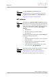
Camera interfaces Outputs PIKE The PIKE cameras have 4 non-inverting outputs with open emitters. These are shown in the following diagram: PIKE OutVCC – Pin 10 GPOut1 – Pin 6 GND R GND GPOut2 – Pin 12 GND R GND GPOut3 – Pin 5 GND R GND GPOut4 – Pin 3 GND R GND Figure 34: Output schematics with external resistors R (pin no.
Camera interfaces OutVCC Resistor value 5V 1 kΩ 12 V 2.4 kΩ 24 V 4.7 kΩ Figure 36: OutVCC (PIKE) Note PIKE L • • • • Voltage above +45 V may damage the optical coupler. The output connection is different to the AVT Dolphin series to achieve higher output swing. Depending on the voltage applied at OutVCC and the type of input which you want to drive, it may be necessary to switch an external resistor in series between GPOut1...4 and ground.
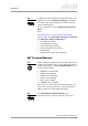
Camera interfaces Outputs STINGRAY The STINGRAY cameras have 4 non-inverting outputs with open emitters. These are shown in the following diagram: intern STINGRAY extern OutVCC – Pin 10 GPOut1 – Pin 6 GND R GND GPOut2 – Pin 12 GND R GND GPOut3 – Pin 5 GND R GND GPOut4 – Pin 3 GND R GND Figure 38: Output schematics with external resistors R (pin no.
Camera interfaces OutVCC Resistor value 5V 1 kΩ 12 V 2.4 kΩ 24 V 4.7 kΩ ≈ 5 mA load Figure 40: OutVCC (STINGRAY) Note STINGRAY L • • • • Voltage above +30 V may damage the optical coupler. The output connection is different to the AVT Marlin series to achieve higher output swing. Depending on the voltage applied at OutVCC and the type of input which you want to drive, it may be necessary to switch an external resistor in series between GPOut1...4 and ground.
Firmware update Firmware update Firmware updates can be carried out without opening the camera. Note For further information: L • • Read the application note: How to update Guppy/ Pike/Stingray firmware at AVT website or Contact your local dealer. Hardware Installation Guide V2.0.
Index Index C Cable GND............................................... 35 camera I/O pinning ....................................... 41 operating .......................................... 46 rear view........................................... 32 camera interfaces..................................... 32 common GND inputs..................................... 43, 44, 45 common vcc outputs................................... 43, 44, 45 Cycle delay input characteristics ...........................
Index O T Open emitter ...................................... 43, 44 operating camera.............................................. 46 operating system FirePackage ....................................... 30 optical coupler cycle delay ........................................ 49 optical filter............................................ 11 outputs ........................................ 40, 42, 57 common vcc ............................ 43, 44, 45 general .............................................