Fast Ethernet Media Converter AT-PC232/POE ◆ Installation Guide 613-001030 Rev.
Copyright © 2008 Allied Telesis, Inc. All rights reserved. No part of this publication may be reproduced without prior written permission from Allied Telesis, Inc. Allied Telesis is a registered trademark of Allied Telesis, Incorporated. All other product names, company names, logos or other designations mentioned herein are trademarks or registered trademarks of their respective owners. Allied Telesis, Inc.
Electrical Safety and Emissions Standards This product meets the following standards. U.S. Federal Communications Commission Declaration of Conformity Manufacturer Name: Allied Telesis, Inc. Declares that the product: Residential Gateway Model Numbers: AT-PC232/POE This product complies with FCC Part 15B, Class B Limits: This device complies with part 15 of the FCC Rules.
Translated Safety Statements Important: The indicates that a translation of the safety statement is available in a PDF document titled “Translated Safety Statements” (613-000990) posted on the Allied Telesis website at www.alliedtelesis.com and on this product CD.
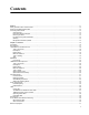
Contents Preface ................................................................................................................................................................................11 Safety Symbols Used in this Document................................................................................................................................12 Where to Find Web-based Guides .....................................................................................................................
Contents Standalone Topology.....................................................................................................................................................31 Back-to-Back Topology .................................................................................................................................................32 Chapter 2: Installation ..........................................................................................................................................
Figures Figure 1. AT-PC232/POE Front Panel.................................................................................................................................16 Figure 2. AT-PC232/POE Back Panel .................................................................................................................................16 Figure 3. LEDs on the AT-PC232/POE Media Converter....................................................................................................26 Figure 4.
Figures 8
Tables Table 1. Safety Symbols .....................................................................................................................................................12 Table 2. IEEE 802.3af Class vs. Power Levels ..................................................................................................................25 Table 3. System Status LED ...........................................................................................................................................
Tables 10
AT-PC232/POE Media Converter Installation Guide Preface This guide provides the hardware installation instructions for your ATPC232/POE Media Converter.
Preface Safety Symbols Used in this Document This document uses the safety symbols defined in Table 1. Table 1. Safety Symbols Symbol 12 Meaning Description Caution Performing or omitting a specific action may result in equipment damage or loss of data. Warning Performing or omitting a specific action may result in electrical shock.
AT-PC232/POE Media Converter Installation Guide Where to Find Web-based Guides The installation and user guides for all Allied Telesis products are available in portable document format (PDF) on our web site at www.alliedtelesis.com. You can view the documents online or download them onto a local workstation or server.
Preface Contacting Allied Telesis This section provides Allied Telesis contact information for technical support as well as sales or corporate information. Online Support You can request technical support online by accessing the Allied Telesis Knowledge Base from the following web site: www.alliedtelesis.com/support. You can use the Knowledge Base to submit questions to our technical support staff and review answers to previously asked questions.
Chapter 1 Overview The AT-PC232/POE Media Converter is designed to extend the distance of your network by converting 10 /100Base Ethernet data between copper and fiber network cables and to provide Power over Ethernet (PoE) power to a Powered Device (PD) connected to the copper port.
Chapter 1: Overview Introduction The AT-PC232/POE Media Converter is a 10/100Base-TX copper to 100Base-FX fiber media converter is designed for both standalone and wall mount use and does not require software configuration or management. Figure 1 illustrates the front panel of the AT-PC232/POE Media Converter. 1356 Figure 1. AT-PC232/POE Front Panel Figure 2 illustrates the back panel of the AT-PC232/POE Media Converter.
AT-PC232/POE Media Converter Installation Guide Key Features The AT-PC232/POE Media Converter comes with the following features: ❒ One 10/100Base-TX twisted pair port with RJ-45 connector ❒ One 100Base-FX multi-mode fiber optic port with a duplex SC connector ❒ Supports half and full duplex operation ❒ Auto-MDI/MDI-X on the 10/100Base-TX port ❒ IEEE 802.3u compliant Auto-Negotiation ❒ IEEE 802.3af Power over Ethernet (PoE) compliant ❒ Supplies up to 15.
Chapter 1: Overview 10/100Base-TX Twisted Pair Port The 10/100Base-TX twisted pair port is described below: Type of Connector The 10/100Base-TX twisted pair port on AT-PC232/POE Media Converter features an 8-pin RJ-45 connector. The port uses four pins when operating at 10 or 100 Mbps. For the port pinout details, refer to Figure 17 , “RJ-45 Connector and Port Pin Layout” on page 54. Port Speed The 10/100Base-TX twisted pair port can operate at 10 or 100 Mbps.
AT-PC232/POE Media Converter Installation Guide Type of Cabling For 10 Mbps, the port requires Category 3 or better 100 ohm shielded or unshielded twisted pair cabling. For 100 Mbps operation, the port requires Category 5 or Enhanced Category 5 (5E) 100 ohm shielded or unshielded twisted pair cabling. Auto MDI/MDI-X The 10/100Base-TX twisted pair port on the AT-PC232/POE Media Converter is auto-MDI/MDI-X and IEEE 802.3ab-compatible.
Chapter 1: Overview 100Base-FX Fiber Optic Port The AT-PC232/POE Media Converter features a single fiber optic port. Type of Connector The fiber optic port features a duplex SC connector. Port Speed The fiber optic port has a fixed operating speed of 100 Mbps. The endnode connected to the port must also be able to operate at 100 Mbps. This speed cannot be changed. Duplex Mode Maximum Distance Type of Cable 20 The fiber optic port can operate in either full-duplex or half-duplex mode.
AT-PC232/POE Media Converter Installation Guide Operating Modes The AT-PC232/POE Media Converter supports these operating modes: Link Test Mode “Link Test Mode,” next “MissingLink Mode” on page 21 “Smart MissingLink Mode” on page 22 Contrary to its name, the Link Test operating mode is not a diagnostic utility. Instead, it uses the Link LEDs to display the current states of the ports.
Chapter 1: Overview switches, one local and the other remote. Switch 1, the remote switch, is connected to port 1, the fiber optic port, on the media converter, while Switch 2, the local device, is connected to port 2, the twisted pair port. If the link to Switch 1 is lost, the line card disables the transmitter on port 2 to signal Switch 2 of the loss of the link to Switch 1.
AT-PC232/POE Media Converter Installation Guide respond by pulsing the transmitter on the twisted pair port and flashing the port’s Link LED about once a second to signal that the failure originated on the fiber optic port. When the connection is reestablished on the fiber optic port, the twisted pair port would automatically resume normal operations to permit the two ports to forward traffic again. The operating mode functions the same if the failure starts on the twisted pair port.
Chapter 1: Overview Power over Ethernet The twisted pair port on the AT-PC232/POE Media Converter features Power over Ethernet (PoE). PoE is a mechanism for supplying power to network devices over the same twisted pair cables used to carry network traffic. This feature can simplify network installation and maintenance by allowing you to use the switch as a central power source for other network devices. A device that receives its power over an Ethernet cable is called a powered device (PD).
AT-PC232/POE Media Converter Installation Guide Power Budgeting The AT-PC232/POE Media Converter can provide a maximum of 15.4 W of power on its twisted pair port (Port 2), along with standard 10/100 Mbps Ethernet functionality. The AT-PC232/POE Media Converter smart power management functionality supports all of the IEEE 802.3af powered device classes listed in Table 2. Table 2. IEEE 802.3af Class vs.
Chapter 1: Overview LEDs The LEDs on the AT-PC232/POE Media Converter, are shown in Figure 3 and are described in the following sections: ❒ “Power LED” on page 26 ❒ “10/100Base-TX Twisted Pair Port LEDs” on page 27 ❒ “100Base-FX Fiber Optic Port LEDs” on page 27 ❒ “Operating Mode LEDs” on page 28 ❒ “PoE PWR LEDs” on page 28 OPERATING MODE LEDs POWER STATUS LED 1356 100BASE-FX PORT 10/100Base-TX PORT LEDs LEDs PoE PWR LEDs Figure 3.
AT-PC232/POE Media Converter Installation Guide 10/100Base-TX Twisted Pair Port LEDs the LEDs for the 10/100Base-TX twisted pair port defined in Table 4, “Twisted Pair Port LEDs” page 27. Table 4. Twisted Pair Port LEDs LED Description Green A valid link has been established on the port. Blinking Green Indicates that when the AT-PC232/POE Media Converter is in SML mode, the LINK on the 100BASE-FX port is lost. Off A port has not established a link with an end node.
Chapter 1: Overview Operating Mode LEDs The three LEDs listed under MODE on the front panel display the operating mode of the media converter. The LEDs are defined in Table 6 on page 28. Beside these LEDs is a button for setting the operating mode. Table 6. Operating Mode LEDs LED PoE PWR LEDs Color Description ML Green MissingLink mode is enabled. SML Green Smart MissingLink mode is enabled. LT Green Link Test mode is enabled.
AT-PC232/POE Media Converter Installation Guide DIP Switches The DIP switches are used to manually configure the operating characteristics of the 10/100BASE-TX twisted-pair port (Port 2), such as port speed, duplex mode, and Auto-Negotation and the duplex mode for the 100BASE-FX fiber port (Port 1). For the DIP switch setting, refer to Table 10 on page 44.
Chapter 1: Overview A Few Basics about Ethernet Switching The AT-PC232/POE Media Converter interconnects network devices, such as workstations, printers, routers, and other Ethernet switches, so that they can communicate with each other by sending and receiving Ethernet frames. MAC Address Table The operation of the AT-PC232/POE Media Converter’s MAC address table reduces the amount of unnecessary traffic by not forwarding packets with a destination address that has been learned on the same port.
AT-PC232/POE Media Converter Installation Guide Network Topologies Standalone Topology A standalone topology uses only one AT-PC232/POE Media Converter between a switch and each end-node. Figure 4 illustrates an example of a standalone topology where several AT-PC232/POE Media Converters are used to interconnect a number of PoE network Power Devices, such as VoIP phones, AT-7400 Wireless Access Points, and a network camera.
Chapter 1: Overview Back-to-Back Topology In some network configurations you may want to interconnect two ATPC232/POE Media Converters in what is referred to as a back-to-back topology. In this topology, the AT-PC232/POE Media Converters not only extend the distance of your network but also converts the fiber optic cable from twisted pair to fiber optic and back again. Figure 5 illustrates one AT-9424T switch at campus 1 and one AT-WA7400 Wireless Access Point on campus 2.
AT-PC232/POE Media Converter Installation Guide Chapter 2 Installation This chapter explains how to install the AT-PC232/POE Media Converter and contains the following sections: ❒ “Verifying the Package Contents” on page 34 ❒ “Planning the Installation” on page 35 ❒ “Desktop Installation” on page 39 ❒ “Wall-Mount Installation” on page 40 ❒ “Cabling the Ports” on page 41 ❒ “Configuring the DIP Switches” on page 44 ❒ “Installing the Power Cord Retaining Clip” on page 45 ❒ “Applying AC Power”
Chapter 2: Installation Verifying the Package Contents Make sure the following items are included in your package. If any item is missing or damaged, contact your Allied Telesis sales representative for assistance.
AT-PC232/POE Media Converter Installation Guide Planning the Installation Observe the following guidelines when planning the installation of your ATPC232/POE Media Converter: ❒ The end-node connected to the 100Base-FX port must be compatible. ❒ The 10/100Base-TX twisted pair port may be set to match the speed and mode of the connected device or allowed to Auto-Negotiate.
Chapter 2: Installation Selecting a Site Reviewing the Safety Guidelines When selecting a site for your AT-PC232/POE Media Converter, observe the following guidelines: ❒ Select a site that is dust-free and moisture-free. ❒ The site should allow for easy access to the fiber optic and twisted pair cables and to the power cord. ❒ If the media converter will be installed on a table, the table should be level and secure. ❒ Do not place objects on top of the media converter.
AT-PC232/POE Media Converter Installation Guide Caution: Using controls, making adjustments to performance, or performing procedures other than those specified herein may result in hazardous radiation exposure. The protection provided by the equipment may be impaired if the equipment is used in a manner not specified by Allied Telesis, Inc. Do not remove the cover from the unit or change any of the internal cables or wiring.
Chapter 2: Installation Warning: Operating Temperature. This product is designed for a maximum ambient temperature of 40° degrees C. E7 All Countries: Install product in accordance with local and National Electrical Codes. E8 Circuit Overloading: Consideration should be given to the connection of the equipment to the supply circuit and the effect that overloading of circuits might have on overcurrent protection and supply wiring.
AT-PC232/POE Media Converter Installation Guide Desktop Installation Install the AT-PC232/POE Media Converter on a desktop, perform the following procedure: 1. Remove the converter from its shipping container and store the packaging material in a safe location. 2. Turn the converter over and place it on a secure surface. 3. Attach the four rubber feet included with the unit to the corners of the bottom of the media converter, as shown in Figure 6. 1362 Figure 6.
Chapter 2: Installation Wall-Mount Installation The AT-PC232/POE Media Converter can be mounted vertically on a wall using the keyholes on the bottom of the switch. Two plastic anchors and screws necessary to mount the switch on a wall are provided in the accessory kit. To wall-mount the switch, perform the following procedure: 1. If attached, remove the rubber feet, data cables, and power cord from the switch. 2. Select a wall location for the switch. 3.
AT-PC232/POE Media Converter Installation Guide Cabling the Ports Perform the following procedures to connect the network cables on the AT-PC232/POE Media Converter. Cabling the Fiber Optic Ports To connect to the fiber optic port (Port 1) on the AT-PC232/POE Media Converter, perform the following procedure. 1. Remove the dust cover from the fiber optic port, as shown in Figure 8 on page 41. 1372 Figure 8. Removing the Dust Cover from the Fiber Optic Port 2.
Chapter 2: Installation ❒ Verify that you are using the appropriate type of fiber optic cabling. ❒ Verify that the operating specifications of the converter’s fiber optic port are compatible with the fiber optic port on the remote endnode. ❒ The fiber optic port has two SC connectors, as shown in Figure 10 on page 42. Each connects to a separate fiber strand. One is for receiving data and the other is for transmitting data.
AT-PC232/POE Media Converter Installation Guide ❒ You can use a straight-through or crossover twisted pair cable to connect any type of network device to a port on the converter. 2. Connect the other end of the RJ-45 cable to the link partner.
Chapter 2: Installation Configuring the DIP Switches Configure the DIP switches using the information in Table 10. Table 10. DIP Switch Settings DIP Switch Port Function Position UP 1 2 2 1 SPEED (Mbps) DUPLEX 3 2 DUPLEX 4 2 AUTO NEG DOWN Description The twisted pair port operates at 10 Mbps.. The fiber port operates at 100 Mbps UP The fiber port operates in half-duplex mode. DOWN The fiber port operates in full-duplex mode. UP The twisted pair port operates in half-duplex mode.
AT-PC232/POE Media Converter Installation Guide Installing the Power Cord Retaining Clip Perform the following procedure to install the power cord retaining clip on the AT-PC232/POE Media Converter: 1. Locate the power cord retaining clip, shown in Figure 12 in the shipping kit that comes with the media converter. Figure 12. Power Cord Retaining Clip 2. Install the clip on the AC power connector on the back panel of the switch.
Chapter 2: Installation Applying AC Power To apply AC power to the AT-PC232/POE Media Converter, perform the following procedure: 1. Position the power cord retaining clip in the up position, shown in Figure 14. SPEE (Mbp D DUP s) LE MOD X AU TO E 10 NEG 100 HALF FULL 1 OFF ON 2 2 1 3 4 2 POR 2 T 100240V AC~ 1381 Figure 14. Power Cord Retaining Clip in the Up Position 2. Plug the power cord into the AC power connector on the back panel of the unit shown in Figure 15.
AT-PC232/POE Media Converter Installation Guide 3. Lower the power cord retaining clip to secure the cord to the ATPC232/POE Media Converter, as shown in Figure 16. SPEE (Mbp D DUPL s) MODEX AU TO E 10 NEG 100 HA LF FULL 1 OFF ON 2 2 1 3 4 2 POR 2 T 100- 240V AC~ 1382 Figure 16. Securing the Power Cord with the Retaining Clip 4. Connect the other end of the power cord to an appropriate AC power outlet. For the power specifications of the media converter, refer to “Electrical Rating” on page 53.
Chapter 2: Installation Verifying the Installation This procedure is used to verify the installation of the media converter. It determines whether or not the fiber optic and twisted pair ports can establish links to their network devices. This procedure assumes the following: The media converter is powered on. The network cables are connected to the ports on the media converter and to the local and remote end-nodes. The local and remote network devices are powered on.
Chapter 3 Troubleshooting Here are suggestions on how to troubleshoot the twisted pair port and the fiber optic port on the AT-PC232/POE Media Converter. Problem 1: The two ports are connected to network devices, but the Link LEDs for the ports are off. Solution: The first step to resolving a link problem between the ports on the media converter and the network devices is to set the operating mode of the unit to the Smart MissingLink mode or the Link Test mode.
Chapter 3: Troubleshooting Verify that the operating specifications of the fiber optic port on the remote network device are compatible with the port on the media converter. For port specifications, refer to “100Base-FX Port Specifications” on page 55. Verify that the correct type of fiber optic cabling is being used. For specifications, refer to “Fiber Optic Cabling and Distance Specifications” on page 35 or “100Base-FX Port 1 Specifications” on page 55.
AT-S63 Web Browser User’s Guide for AT-9400 Stacks The two network devices are operating in different duplex modes. The media converter performs best when its two network devices and its two ports all use the same duplex mode. There could be an intermittent problem with one of the network devices connected to the media converter or with a cable. To determine whether this might be the problem, set the unit to the Link Test mode and observe the Link LEDs of the ports.
Chapter 3: Troubleshooting 52 Section II: Advanced Operations
Appendix A Technical Specifications Physical Dimensions: WxDxH 15.5 cm x 13.1 cm x 4.0 cm (6.10 in x 5.16 in x 1.58 in) Weight: .748 Kg (1.65 lb.) Operating Temperature: 0° C to 40° C (32° F to 104° F) Storage Temperature: -25° C to 70° C (-13° F to 158° F) Operating Humidity: 5% to 90% noncondensing Storage Humidity: 5% to 95% noncondensing Maximum Operating Altitude: 3,048 m (10,000 ft) Maximum Non-Operating Altitude: 4,000 m (13,100 ft) AC Input Supply Requirements: 100-240 VAC, 1.
Chapter : Technical Specifications Agency Certifications RFI Emissions FCC Class B, EN55022 Class B, C-TICK, CE Immunity EN55024 Electrical Safety EN60950 (TUV), UL 60950 (CULUS) Standard IEEE 802.3, IEEE 802.3u RoHS RoHS/China RoHS compliant MTBF 580,000 Hrs 10/100Base-TX Port Pinouts Figure 17 illustrates the pin layout to an RJ-45 connector and port. 1 8 8 1 Figure 1.
AT-PC232/POE Media Converter Installation Guide Table 12 lists the RJ-45 port pin signals when a twisted pair port is operating in the MDI-X configuration at 10 or 100 Mbps. Table 2. MDI-X Pin Signals (10/100Base-TX) Pin Signal 1 RX+ 2 RX- 3 TX+ 6 TX- 100Base-FX Port Specifications Table 13 lists the operating specifications for fiber port (Port 1) . Table 3. 100Base-FX Port 1 Specifications Property Value General Maximum Distance 2 km Fiber Optic Cable 50/125 µm or 62.
Chapter : Technical Specifications 56
Appendix B Cleaning Fiber Optic Connectors The fiber optic connector consists of a fiber optic plug and its adapter. The end of the fiber optic cable is held in the core of the ferrule in the plug. Light signals are transmitted through the core of the fiber. Even minor smudges or dirt on the end face of the fiber, completely invisible to the naked eye, can disrupt light transmission and lead to failure of the component or of the entire system.
Appendix B: Cleaning Fiber Optic Connectors Using a Cartridge-Type Cleaner H OPEN W cti re Di A E AT Pipingon Fiber optic cartridge cleaners are available from many vendors and are typically called “cartridge cleaners,” as shown in Figure 20. Figure 20. Cartridge Cleaner Note Do not use compressed air or aerosol air to clean a fiber optic connector. Warning: Do not stare into the laser beam. L2 To clean a fiber optic connector using a cartridge cleaner, perform the following procedure. 1.
AT-LX44000 Multi-Protocol WDM Transport System Installation Guide 2. Place the ferrule tip on the exposed cleaning surface and rub the ferrule in a downward direction, as shown in Figure 21. 102 Figure 21. Rubbing the Ferrule Tip on the Cleaning Surface Note Rub the ferrule tip on the cleaning surface in one direction only. 3. When you reach the end of the cleaning surface, pick up the ferrule tip, rotate and place it at the top and rub downwards at least 2 times.
Appendix B: Cleaning Fiber Optic Connectors Using a Swab Specially treated swabs (stick cleaners) are available for cleaning inside connector adapters or hard-to-reach ferrule tips. These swabs, often referred to as “lint free” or “alcohol free” swabs, are available from many vendors, as shown in Figure 22. Stick cleaners are available in both 2.5 mm and 1.25 mm sizes for use on SC and MU connectors respectively. Note NEVER use a household cotton swab and/or alcohol to clean a fiber optic connector.
AT-LX44000 Multi-Protocol WDM Transport System Installation Guide To clean a recessed ferrule using a swab, perform the following procedure. 1. Insert the swab into the adapter as shown in Figure 23 and rub the ferrule tip with the swab. 157 Figure 23. Cleaning a Recessed Ferrule 2. If desired, repeat step 1. 3. If a fiber inspection scope is available, use the scope to inspect the connector to make sure that it is clean and to check for scratches, pits, or other problems that may affect performance.
Appendix B: Cleaning Fiber Optic Connectors 62