
User's Manual


Chapter 1: Overview
28
High-power
Switches
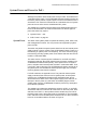
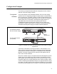
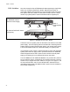
The power supply modules can support just one high-power switch at a
time. In the example in Figure 11 on page 28, the chassis is supporting the
AT-x610-24Ts and AT-x610-48Ts Switches, with two power supply
modules, one for each switch. Even though the AT-x610-24Ts Switch is a
low-power unit, the AT-x610-48Ts Switch must have its own dedicated
power supply module because it is a high-power device.
Figure 11. Example of Low-power and High-power Switches
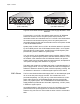
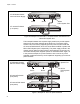
When a high-power, non-PoE+ switch is connected to the AT-RPS3000
Chassis, it responds just like a low-power switch. It places its internal
power supply in the redundant state and draws its system power from the
chassis.
In Figure 12 on page 29, the high-power, non-PoE+ AT-x610-48Ts and
AT-x610-48Ts/X Switches are supported by separate power supply
modules, with the AT-x610-48Ts Switch supported by the module in slot A
and the AT-x610-48Ts/XSwitch powered by the module in slot B. If the
chassis stops supplying system power to the switches, they activate their
internal power supplies.
AT-x610-24Ts Switch
AT-x610-48Ts Switch
AT-RPS3000 Chassis
(Low-power)
(High-power)
with Two Power Supplies
B
B
1
2
3
4
SYSTEM
PoE+ / SYSTEM PoE+ / SYSTEM
SYSTEM
MODULE B
MODULE A
A
A
AT-P WR 800
DC OUT
FAULT
100-240 VAC~12A MAX
AT-P WR 800
DC POWER
FAULT
100-240 VAC~12A MAX
100-240 VAC~12A MAX
POWER SUPPLY
RPS
READY
RPS INPUT
12V/21A MAX
WARNING
This unit may have more than one power input. To reduce the risk of
electric shock, disconnect both A/C and RPS inputs before servicing
unit.
100-240 VAC~12A MAX
POWER SUPPLY
RPS
READY
RPS INPUT
12V/21A MAX
WARNING
This unit may have more than one power input. To reduce the risk of
electric shock, disconnect both A/C and RPS inputs before servicing
unit.
2136
Slot A Slot B