
User's Manual

Chapter 1: Overview
34
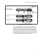
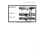
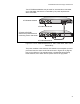
Figure 18. Example of an Invalid Configuration - A
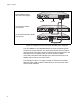
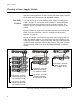
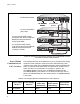
In the example in Figure 19 on page 35, the power supply in slot A is
supporting a low-power switch and a high-power switch. This configuration
is invalid because the power supply modules can support only one switch
if it is a high-power switch. You could resolve the problem by installing a
power supply module in slot B and connecting one of the switches to RPS
port 3 or 4. The resolution is shown in Figure 11 on page 28.
100-240 VAC~12A MAX
POWER SUPPLY
RPS
READY
RPS INPUT
12V/21A MAX
WARNING
This unit may have more than one power input. To reduce the risk of
electric shock, disconnect both A/C and RPS inputs before servicing
unit.
B
B
1
2
3
4
SYSTEM
PoE+ / SYSTEM PoE+ / SYSTEM
SYSTEM
MODULE B
MODULE A
A
A
AT-P WR 800
DC OUT
FAULT
100-240 VAC~12A MAX
AT-PNL800/1200
100-240 VAC~12A MAX
POWER SUPPLY
RPS
READY
RPS INPUT
12V/21A MAX
WARNING
This unit may have more than one power input. To reduce the risk of
electric shock, disconnect both A/C and RPS inputs before servicing
unit.
2211
AT-x610-24Ts Switch
AT-x610-24Ts/X Switch
AT-RPS3000 Chassis
(Low-power)
(Low-power)
with One Power Supply
Slot A
Slot B