
User's Manual
Chapter 1: Overview
38
Wiring
Implementation
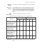
The IEEE 802.3af standard defines two methods by which a PSE, such as
the switch, can transmit DC power over twisted pair cables to PDs. These
methods, known as modes A and B, identify the wire strands the switch
should use when sending DC power to a PD.
Twisted pair cabling typically consists of eight strands. With 10Base-T and
100Base-TX devices, the strands connected to pins 1, 2, 3, and 6 on the
RJ-45 connectors carry the network traffic while strands connected to pins
4, 5, 7, and 8 are unused. With 1000Base-T devices, all eight strands are
used to carry network data.
It takes four strands to deliver DC power to a PD. With Mode A, the power
is delivered on pins 1, 2, 3, and 6. These are the same pins in 10Base-T
and 100Base-TX devices that carry the network data. With mode B, the
power is provided over the spare strands.
The ports on the AT-8100S/24POE Switch deliver the power using pins 4,
5, 7, and 8, which corresponds to mode B in the IEEE 802.3af standard.
Powered devices that comply with the IEEE 802.3af standard are required
to support both power delivery methods. Legacy devices that do not
comply with the standard will work with the switch if they are powered on
pins 4, 5, 7, and 8.