
User's Manual

Installation & Safety Guide 13
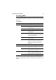
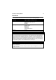
Checking LEDs
The following tables outline how the switch and expansion modules report faults
and operational activities. Expansion modules are optional and can be purchased
separately.
Use the Mode Select button to toggle the Mode LEDs to the desired state.
Toggling the Mode Selection button does not affect the normal operations of the
switch.
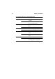
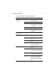
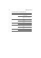
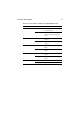
System LEDs
LED State Description
FAULT Off Switch operation is normal.
Red The switch or management software is
malfunctioning.
1 flash A switch fan has failed.
3 flashes The main PSU has failed and the RPS is now
providing power.
4 flashes The RPS Monitor is set to ON, and the RPS
is not functioning, either because it has failed
or has been switched off.
5 flashes The RPS Monitor is set to ON, but the RPS
is not connected.
7 flashes For the AT-8624T/2M and AT-8624PoE
switches: An expansion module has been
inserted or removed while the switch is
powered on.
MASTER Off This LED is not supported.
RPS Green An optional redundant power supply is
connected to the switch.
Off There is no optional redundant power
supply connected to the switch.
PWR Green The switch is receiving power and the
voltage is within the acceptable range.
Off The switch is not receiving power.