ALLIEDVIEW-UM 1.
Allied Telesis AlliedView-UM 1.6 User's Guide Copyright © 2002-2007 Allied Telesis K. K. All rights reserved. No part of this publication may be reproduced without prior written permission from Allied Telesis K. K. Allied Telesis K. K. reserves the right to make changes in specifications and other information contained in this document without prior written notice. The information provided herein is subject to change without notice. In no event shall Allied Telesis K. K.
Allied Telesis AlliedView-UM 1.6 User's Guide TABLE OF CONTENTS 1 INTRODUCTION .................................................................................................... 6 1.1 1.2 2 A GUIDED TOUR ........................................................................................................ 7 2.1 2.2 2.3 2.4 3 CREATING A RELEASE UPGRADE PROFILE ......................................................... 43 SAVING A RELEASE UPGRADE PROFILE .............................................
Allied Telesis AlliedView-UM 1.6 User's Guide 9.3 9.4 10 CONFIGURATION FILE UPDATE ................................................................................... 67 10.1 10.2 10.3 10.4 11 CREATING AN ENABLE FEATURES PROFILE ....................................................... 99 SAVING AN ENABLE FEATURES PROFILE ......................................................... 101 LOADING AN ENABLE FEATURES PROFILE .......................................................
Allied Telesis AlliedView-UM 1.6 User's Guide 18.2 SPECIAL RULES ON ROLLBACKS...................................................................... 121 18.3 PERFORMING A ROLLBACK ON A DEVICE ........................................................ 122 18.4 PERFORMING A ROLLBACK ON AN OPERATION PROFILE .................................. 124 19 LICENSE REGISTRATION.......................................................................................... 127 20 OPTIONS ....................................
Allied Telesis AlliedView-UM 1.6 User's Guide 1 INTRODUCTION AlliedView-UM is a Java-based application that allows fast and efficient distribution of Software Upgrades, Patches, GUI Resource files, Help, Configuration files and Script files on Allied Telesis network devices. It provides a batch method of downloading software or a file onto devices via TFTP or HTTP. It also provides the ability to enable the downloaded software or file and enable features on multiple devices. 1.
Allied Telesis AlliedView-UM 1.6 User's Guide 2 A GUIDED TOUR This section introduces all the basic features of AlliedView-UM. This section is not intended to be a reference and will thus not explain all the details. 2.1 LAUNCHING THE APPLICATION To begin the tour, start the application using any of the following methods: For Windows systems: Double-click on the executable file "um.exe" or its corresponding shortcut through Windows Explorer.
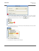
Allied Telesis AlliedView-UM 1.6 User's Guide The image below illustrates the initial screen display of AlliedView-UM. 2.2 CREATING A DEVICE Before you can use the main functions of AlliedView-UM , you will need to add Devices on the Device Families pane. To do that, follow these simple steps. 1. Click on the Device->Add Device Group option. This will display the “Add Device Group” dialog box.
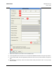
Allied Telesis AlliedView-UM 1.6 User's Guide 2. Click on the “Device Family” dropdown list and select “Rapier”. If you do not have any Rapier devices, select the appropriate device family for the device that you currently have. On the Device Group Name field, input “Test Group” and click on the button. 3. Look at the Device Families pane. You should see your newly created group ("Test Group") added under the Rapier Family root node. 4. Click on the Device->Add Device option. 5.
Allied Telesis AlliedView-UM 1.6 User's Guide 7. Input the IP address of your device in the IP Address field. 8. In the Login Name field, enter the user account name that AlliedView-UM will use to login to your device. 9. In the Password field, enter the appropriate password for the account you have entered in the previous step. 10. The SNMP Read Community, Timeout and Retries fields already have default values. You may change these if needed.
Allied Telesis AlliedView-UM 1.6 User's Guide 11. Click on the button. If the IP Address, Login Name, Password, and SNMP Read Community that you specified are correct, then the Device Family, Device Model Serial Number, System Name, System Description and Configuration File fields should now be set. If an error occurs, please re-check the values you entered in steps (6) to (9). 12. Finally, click on the button to add the device. 13. Your new device should now be added.
Allied Telesis AlliedView-UM 1.6 User's Guide 2.3 UPGRADING SOFTWARE In this section, we will be performing a simple patch upgrade using the Patch Upgrade operation. Before proceeding, make sure you have added one or more devices. If you have not done so, please go back to the previous section, "Creating a Device". You will also need to have access to an appropriate patch upgrade file for your device. button on the Operations Selection Pane. This will display Click on the the Patch Upgrade pane.
Allied Telesis AlliedView-UM 1.6 User's Guide 3 MAIN WINDOW After successfully starting the application, the following window will be initially displayed: The Main Window is divided into 4 major panes (or regions), namely the (1) Device Families Pane, the (2) Operations Selection Pane, the (3) Operations Pane and the (4) Operation Logs Pane. 3.1 DEVICE FAMILIES PANE The Device Families Pane is used to manage the devices that AlliedView-UM can interface with.
Allied Telesis AlliedView-UM 1.6 User's Guide The root nodes of the Device Families represent the AT Device Families that are currently supported by this application. The AT Device Family root node is represented by a ( ) icon followed by the AT Device Family name. Each AT Device Family root node can contain Device Group nodes. A Device Group node is represented by a ( ) icon followed by the Device Group name. Finally, a Device Group node can contain Device nodes.
Allied Telesis AlliedView-UM 1.6 User's Guide Clicking on any of the buttons in the Operation Selections Pane will display the appropriate Operations Pane. For example, if you click on the Upgrade Operations Pane will be displayed.
Allied Telesis AlliedView-UM 1.6 User's Guide 3.3 OPERATIONS PANE This is where operation panes for creating operation profiles are displayed. For instance, the figure above displays the Release Upgrade (AlliedWare) pane after the user clicks on the 3.4 button. OPERATION LOGS PANE The Operation Logs Pane displays the status and results of operations performed.
Allied Telesis AlliedView-UM 1.
Allied Telesis AlliedView-UM 1.6 User's Guide 4 DEVICE GROUPS A device group represents a logical grouping used to manage devices. A device group must first be created before any device can be defined. 4.1 CREATING A DEVICE GROUP 1. Click on the Device->Add Device Group option. This will display the “Add Device Group” dialog box. 2. Select the Device Family where your new Device Group will be added to. 3. Enter the name of your device group in the Device Group Name field. 4. Finally, click on the 4.
Allied Telesis AlliedView-UM 1.6 User's Guide 2. Click on the Device->Delete Device Group option. 3. A confirmation dialog box will be displayed. Click on to proceed with the deletion. Method 2: 1. Right click on the device group node to be deleted. A popup menu will appear. 2. Select the Delete option. 3. A confirmation dialog box will be displayed. Click to proceed with the deletion. NOTE: Any device under the deleted device group will be deleted as well.
Allied Telesis AlliedView-UM 1.6 User's Guide RENAMING A DEVICE GROUP Method 1: 4.3 1. On the Device Families Pane, select the device group node to be renamed. The device group pane will be displayed. The Name field contains the currently assigned name for that device group. 2. Click on the Device->Rename Device Group option. 3. Type in the new name in the Device Group Name field. 4. Finally, click on the PN 613-000381 Rev B button.
Allied Telesis AlliedView-UM 1.6 User's Guide Method 2: 1. Right click on the Device Group node to be renamed. 2. Select the “Rename” option to display the Rename Device Group dialog box. 3. Rename the device group. Then click on the 4.4 button. LOADING DEVICE GROUPS Device groups which have been closed can be reloaded using this function. 1. Click on File->Load Device Groups on the main menu.
Allied Telesis AlliedView-UM 1.6 User's Guide 2. Specify the file(s) to be loaded. 3. Click the button. 4. Once the loading is complete, the device groups with their respective devices will be displayed in the Device Families Pane. CLOSING DEVICE GROUPS Unlike deleting, closing device groups will only "unload" the device groups. Unloaded device groups can be "reloaded" later using the "Load Device Groups" function. 4.5 1.
Allied Telesis AlliedView-UM 1.6 User's Guide 3. Select the device group to close. 4. Finally, click on the PN 613-000381 Rev B button.
Allied Telesis AlliedView-UM 1.6 User's Guide 5 DEVICE DEFINITIONS Devices must first be defined before they can be included in any operation. Also, TELNET LOGIN support for a device must be enabled in order for AlliedView-UM to interface with it. 5.1 CREATING A DEVICE DEFINITION 1. Before you add any new devices, make sure you have already defined a Device Group. If you have not done so, please create one using the steps described in the previous section, Creating a Device Group. 2.
Allied Telesis AlliedView-UM 1.6 User's Guide 3. The Add New Device dialog box will be displayed with the input fields blank or set to a default value: IP Address - This is the IP Address of the device. Login Name - This is the user account recognized by the device. AlliedView-UM will login to the device using this account to perform the different operations. Password - This is the password for the login name.
Allied Telesis AlliedView-UM 1.6 User's Guide software. You may ignore this field when adding devices that use non-AlliedWare™ management software.) Timeout - When retrieving the device's information, this is the number of seconds AlliedView-UM will wait for a response before retrying. (This field only applies to devices that use AlliedWare™ management software. You may ignore this field when adding devices that use non-AlliedWare™ management software.
Allied Telesis AlliedView-UM 1.6 User's Guide 4. Once the fields in step (3) have been set, click on the PN 613-000381 Rev B button.
Allied Telesis AlliedView-UM 1.6 User's Guide 5. AlliedView-UM will retrieve the Serial Number and Device Model. If the retrieval is successful, the Device Family, Device Model, Serial Number, System Name, System Description and Configuration File fields will be set to that of the device. (For devices that run on non-AlliedWare™ management software, the Serial Number will be set to "N/A".) The Device Group combo box will also be populated with the groups defined under the device family. 6.
Allied Telesis AlliedView-UM 1.6 User's Guide 7. After the device is added, the Device Families Pane will be updated with a new node represented by the IP address of that device. 8. If you decide not to continue adding the device, click on the 5.2 button. LOADING DEVICE DEFINITIONS FROM A COMMA SEPARATED VALUE (CSV) FILE An alternative way of adding or updating multiple devices is by pre-defining them in a Comma Separated Value (CSV) file.
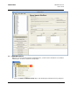
Allied Telesis AlliedView-UM 1.6 User's Guide 1. To load device definitions from a CSV file, click on File->Import/Update Devices on the menu. button. AlliedView-UM will then open that file and 2. Specify the file to import and click on the import the CSV format device definition entries it contains.
Allied Telesis AlliedView-UM 1.6 User's Guide 3. After the import process is completed, AlliedView-UM will display a summary window containing a list of the devices that were imported or updated and those that encountered errors. Click on the button to close the window.
Allied Telesis AlliedView-UM 1.6 User's Guide 4. The IP addresses of the newly imported files will be added to the Device Families Pane under the specified device group. 5. If a device device group is not specified for a device entry in the CSV file, AlliedView-UM will create a group called, "Default" under the appropriate Device Family. It will then assign the device to that group.
Allied Telesis AlliedView-UM 1.6 User's Guide 5.3 VIEWING DEVICE DEFINITIONS 1. Double-click the IP address of a device on the Device Families Pane.
Allied Telesis AlliedView-UM 1.6 User's Guide 2. The Edit Device dialog box will be displayed containing information for the selected device.
Allied Telesis AlliedView-UM 1.6 User's Guide 5.4 MODIFYING DEVICE DEFINITIONS 1. Display the Device Definition to be modified. (See the previous section, Viewing Device Definitions) 2. Once the Edit Device dialog box is displayed, the information for the selected device can modified. 3.
Allied Telesis AlliedView-UM 1.6 User's Guide 4. After modifying the values, click on PN 613-000381 Rev B to apply the changes.
Allied Telesis AlliedView-UM 1.6 User's Guide DELETING DEVICE DEFINITIONS Method 1: 5.5 1. Click the IP address of the device on the Device Families Pane. 2. Select Device->Delete Device from the main menu. 1. A confirmation dialog box will be displayed. Click to proceed with the deletion. Method 2: 1. Right click on the IP address of the device on the Device Families Pane. 2. Select Delete from the popup menu. 3.
Allied Telesis AlliedView-UM 1.6 User's Guide 6 EXPORTING DEVICE SERIAL NUMBERS This function only applies to devices that use AlliedWare™ management software. AlliedView-UM has the option to export the Serial Number of devices to a serial number file. The file can then be uploaded onto WebGen. WebGen reads the serial numbers from the file and generates the corresponding license list file needed for performing a Release Upgrade or an Enable Features operation.
Allied Telesis AlliedView-UM 1.6 User's Guide 2. The Export Serial Numbers dialog box will be displayed. Select the devices by moving their respective IP addresses from the Available Devices list into the Selected Devices list. 3. If there are plenty of devices available, use the Family, Group and Model filters to narrow down the selection process. 4. After making the selection, generate the License Request File by clicking the button. 5. The Save Serial Numbers dialog box will be displayed. 6.
Allied Telesis AlliedView-UM 1.6 User's Guide 7. Finally, click the 6.1 button. LICENSE LIST FILE FOR RELEASE UPGRADE (ALLIEDWARE) OPERATIONS Create a text file containing the following information: release_filename release version password : : Example: 86s-261.
Allied Telesis AlliedView-UM 1.
Allied Telesis AlliedView-UM 1.6 User's Guide 7 RELEASE UPGRADE OPERATION AlliedView-UM provides two types of Release Upgrade Operations: Release Upgrade (AlliedWare) and Release Upgrade (Other). Devices that use AlliedWare™ software can be upgraded with new software release files through the Release Upgrade (AlliedWare) Operation pane. The software release files for these devices require special licenses in order to be properly installed. To display this pane, click on the Selection pane.
Allied Telesis AlliedView-UM 1.6 User's Guide Devices that do not use AlliedWare™ software can be upgraded with new software release files through the Release Upgrade (Other) Operation pane. The software release files for these devices do not require any licenses. To display this pane, click on the Selection pane. 7.
Allied Telesis AlliedView-UM 1.6 User's Guide 1. License List Filename - Specify the license key list to use for the release. After choosing the License List File, the release file to be used will be displayed in the Release Filename field. 2. Release Filename - This is a read-only field that displays the filename of the software release file that will be installed on the target device(s). 3. Upload Options - Choose one of the following options: Upload - Uploads the release file only.
Allied Telesis AlliedView-UM 1.6 User's Guide 1. Release Filename - Specify the software release file to be used. 2. Boot Filename - Specify the boot file to be used. This is only applicable to the AT-8000S Family Devices.
Allied Telesis AlliedView-UM 1.6 User's Guide Upload Parameters 1. Server - This is the address for the server that contains the release file. If the server is a TFTP server, the server address should be specified as an IP address. If the server is an HTTP server, the server address should be specified as a URL. 2. Destination - This sets the location where the new release file will be stored. This can be set to FLASH or NVS. 3. Protocol - This specifies the protocol that the server supports.
Allied Telesis AlliedView-UM 1.6 User's Guide 1. Clicking the button moves all selected/highlighted IP addresses from the Available Devices list to the Selected Devices list. 2. Clicking the Devices list. button moves all IP addresses form the Available Devices list to the Selected 3. Clicking the button moves all the selected/highlighted IP address from the Selected Devices list to the Available Devices list. 4. Clicking the Devices list.
Allied Telesis AlliedView-UM 1.6 User's Guide 7.2 SAVING A RELEASE UPGRADE PROFILE 1. Click on the button. 2. The Save Release Upgrade (AlliedWare) or (Other) dialog box will be displayed. 3. Specify the filename. 4. Finally, click on the PN 613-000381 Rev B button.
Allied Telesis AlliedView-UM 1.6 User's Guide 7.3 LOADING A RELEASE UPGRADE PROFILE 1. Click on the button. 2. A confirmation dialog box will be displayed. Click to proceed. 3. The Load Release Upgrade (AlliedWare) or (Other) Profile dialog box will be displayed. Specify the filename of the profile to be loaded. 4. Finally, click on the Operation profile. PN 613-000381 Rev B button.
Allied Telesis AlliedView-UM 1.6 User's Guide NOTE: The Release Upgrade (AlliedWare) or (Other) Operation profile contains the Selected Devices list. While loading, AlliedView-UM checks each item in this list against the currently loaded devices in the Device Families Pane. Only entries that have a matching device in the Device Families Pane will be loaded and added to the Selected Devices list in the Release Upgrade pane.
Allied Telesis AlliedView-UM 1.6 User's Guide 7.4 STARTING THE RELEASE UPGRADE (ALLIEDWARE) OR (OTHER) OPERATION The Release Upgrade Operation can only be started when the parameters have been properly set. 1. Click on the button. 2. A progress window will be displayed, indicating the overall status of the operation. When the Release Upgrade operation ends, the Operation Logs pane will be updated to contain detailed information about the operation for each device.
Allied Telesis AlliedView-UM 1.6 User's Guide 8 INTERIM/MAINTENANCE RELEASE UPGRADE OPERATION Devices can be upgraded with a new Interim or Maintenance Release file through the Interim/Maintenance Release Upgrade Operation pane. To display this pane, click on the Selection pane. button on the Operations The Interim/Maintenance Release Upgrade Operation is only applicable to devices that use AlliedWare™ management software.
Allied Telesis AlliedView-UM 1.6 User's Guide 8.1 CREATING AN INTERIM/MAINTENANCE RELEASE UPGRADE PROFILE Software Selection 1. Interim/Maintenance Release Filename - Specify the interim/maintenance release file to use. 2. Upload Options - Choose one of the following options: Upload - Uploads the interim/maintenance release file only. Upload and enable - Uploads and enables the interim/maintenance release file only.
Allied Telesis AlliedView-UM 1.6 User's Guide Upload Parameters 1. Server - This is the address for the server that contains the interim/maintenance release file. If the server is a TFTP server, the server address should be specified as an IP address. If the server is an HTTP server, the server address should be specified as a URL. 2. Destination - This sets the location where the new interim/maintenance release file will be stored. This can be set to FLASH or NVS. 3.
Allied Telesis AlliedView-UM 1.6 User's Guide 8.2 SAVING AN INTERIM/MAINTENANCE RELEASE UPGRADE PROFILE 1. Click on the button. 2. The Save Interim/Maintenance Release Upgrade Profile dialog box will be displayed. 3. Specify the filename. 4. Finally, click on the PN 613-000381 Rev B button.
Allied Telesis AlliedView-UM 1.6 User's Guide 8.3 LOADING AN INTERIM/MAINTENANCE RELEASE UPGRADE PROFILE 1. Click on the button. 2. A confirmation box will be displayed. Click to proceed. 3. The Load Interim/Maintenance Release Upgrade Profile dialog box will be displayed. Specify the filename of the profile to be loaded. 4. Finally, click on the button. AlliedView-UM will load the specified Interim/Maintenance Release Upgrade Operation profile.
Allied Telesis AlliedView-UM 1.6 User's Guide NOTE: The Interim/Maintenance Release Upgrade Operation profile contains the Selected Devices list. While loading, the AlliedView-UM checks each item in this list against the currently loaded devices in the Device Families Pane. Only entries that have a matching device in the Device Families Pane will be loaded and added to the Selected Device list in the Interim/Maintenance Release Upgrade pane.
Allied Telesis AlliedView-UM 1.6 User's Guide 8.4 STARTING THE INTERIM/MAINTENANCE RELEASE UPGRADE OPERATION The Interim/Maintenance Release Upgrade Operation can only be started when the parameters have been properly set. 1. Click on the button. 2. A progress window will be displayed, indicating the overall status of the operation. When the Interim/Maintenance Release Upgrade operation ends, the Operation Logs pane will be updated to contain detailed information about the operation for each device.
Allied Telesis AlliedView-UM 1.6 User's Guide NOTE: Aborting an operation may leave some devices in an undesirable state.
Allied Telesis AlliedView-UM 1.6 User's Guide 9 PATCH UPGRADE OPERATION Devices can be upgraded with patches through the Patch Upgrade Operation pane. To display this pane, click on the pane. button on the Operations Selection The Patch Upgrade Operation is only applicable to devices that use AlliedWare™ management software.
Allied Telesis AlliedView-UM 1.6 User's Guide 9.1 CREATING A PATCH UPGRADE PROFILE Software Selection 1. Patch Filename - Specify the Patch file to use. 2. Upload Options - Choose one of the following options: Upload - Uploads the Patch file only. Upload and set as temporary - Uploads, enables, and sets the Patch file as the temporary Patch file. Upload and set as preferred - Uploads, enables and sets the Patch file as the preferred Patch file. 3.
Allied Telesis AlliedView-UM 1.6 User's Guide Upload Parameters 1. Server - This is the address for the server that contains the Patch file. If the server is a TFTP server, the server address should be specified as an IP address. If the server is an HTTP server, the server address should be specified as a URL. 2. Destination - This sets the location where the new Patch file will be stored. This can be set to FLASH or NVS. 3. Protocol - This specifies the protocol that the server supports.
Allied Telesis AlliedView-UM 1.6 User's Guide 9.2 SAVING A PATCH UPGRADE PROFILE 1. Click on the button. 2. The Save Patch Upgrade Profile dialog box will be displayed. 3. When prompted, specify the filename. 4. Finally, click on the PN 613-000381 Rev B button.
Allied Telesis AlliedView-UM 1.6 User's Guide 9.3 LOADING A PATCH UPGRADE PROFILE 1. Click on the button. 2. A confirmation box will be displayed. Click to proceed. 3. The Load Patch Upgrade Profile dialog box will be displayed. Specify the filename of the profile to be loaded. 4. Finally, click on the Operation profile. PN 613-000381 Rev B button.
Allied Telesis AlliedView-UM 1.6 User's Guide NOTE: The Patch Upgrade Operation profile contains the Selected Devices list. While loading, AlliedView-UM checks each item in this list against the currently loaded devices in the Device Families Pane. Only entries that have a matching device in the Device Families Pane will be loaded and added to the Selected Devices list in the Patch Upgrade Operation pane. A summary window will be displayed indicating which entries were successfully added.
Allied Telesis AlliedView-UM 1.6 User's Guide 9.4 STARTING THE PATCH UPGRADE OPERATION The Patch Upgrade Operation can only be started when the parameters have been properly set. 1. Click on the button. 2. A progress window will be displayed, indicating the overall status of the operation. When the Patch Upgrade operation ends, the Operation Logs pane will be updated to contain detailed information about the operation for each device. 3.
Allied Telesis AlliedView-UM 1.6 User's Guide 10 CONFIGURATION FILE UPDATE Device configurations can be updated through the Configuration File Update Operation pane. To display this pane, click on the pane.
Allied Telesis AlliedView-UM 1.6 User's Guide 10.1 CREATING A CONFIGURATION FILE UPDATE PROFILE Update Options 1. Upload Options - Choose one of the following options: Upload - Uploads the Configuration file only. Upload and set - Uploads and sets the configuration file as the Configuration to be used by the device. 2. File Deletion Options Delete old configuration files if memory space is insufficient checkbox - If the devices to be upgraded have limited memory space (e.g.
Allied Telesis AlliedView-UM 1.6 User's Guide NOTE: For the AT-8000S Family, • Choosing the “Upload” means that the contents of the specified configuration file will be added to those in the running configuration of the device, thus, the loaded configuration will take effect as soon as the operation ends. However, the loaded configuration will not be copied to the startup configuration which might be erased after rebooting the device.
Allied Telesis AlliedView-UM 1.6 User's Guide Upload Parameters 1. Server - This is the address for the server that contains the Configuration file. If the server is a TFTP server, the server address should be specified as an IP address. If the server is an HTTP server, the server address should be specified as a URL. 2. Destination - This sets the location where the new Configuration file will be stored. This can be set to FLASH or NVS. 3. Protocol - This specifies the protocol that the server supports.
Allied Telesis AlliedView-UM 1.6 User's Guide Device Selection The Available Devices list will be initially populated with the IP addresses of the devices which have a Configuration file specified in its device definition. Except for the above mentioned process, device selection is similar to that of the Release Upgrade Operation pane.
Allied Telesis AlliedView-UM 1.6 User's Guide 10.2 SAVING A CONFIGURATION FILE UPDATE PROFILE 1. Click on the button. 2. The Save Configuration File Update Profile dialog box will be displayed. 3. Specify the filename. 4. Finally, click on the PN 613-000381 Rev B button.
Allied Telesis AlliedView-UM 1.6 User's Guide 10.3 LOADING A CONFIGURATION FILE UPDATE PROFILE 1. Click on the button. 2. A confirmation box will be displayed. Click to proceed. 3. When prompted, specify the filename of the profile to load. 4. Finally, click on the Update Operation profile file. PN 613-000381 Rev B button.
Allied Telesis AlliedView-UM 1.6 User's Guide NOTE: The Configuration File Update profile contains the Selected Devices list. While loading, AlliedView-UM checks each item in this list against the currently loaded devices in the Device Families Pane. Only entries that have a matching device in the Device Families Pane will be loaded and added to the Selected Devices list in the Configuration File Update Operation pane. A summary window will be displayed indicating which entries were successfully added.
Allied Telesis AlliedView-UM 1.6 User's Guide 10.4 STARTING THE CONFIGURATION FILE UPDATE OPERATION The Configuration File Update Operation can only be started when the parameters have been properly set. 1. Click on the button. 2. A progress window will be displayed, indicating the overall status of the operation. When the Configuration File Update operation ends, the Operation Logs pane will be updated to contain detailed information about the operation for each device. 3.
Allied Telesis AlliedView-UM 1.6 User's Guide NOTE: Aborting an operation may leave some devices in an undesirable state.
Allied Telesis AlliedView-UM 1.6 User's Guide 11 EXECUTE SCRIPT FILE Script files can be uploaded and executed on target devices through the Execute Script File Operation Pane To display this pane, click on the Selection pane. button on the Operations The Execute Script File Operation is only applicable to devices that use AlliedWare™ management software.
Allied Telesis AlliedView-UM 1.6 User's Guide 11.1 CREATING AN EXECUTE SCRIPT FILE PROFILE Script File Selection 1. Script Filename - Specify the Script file to use. 2. Upload Options - Choose one of the following options: Upload - Uploads the Script file only. Upload and execute - Uploads and executes the script file. 3.
Allied Telesis AlliedView-UM 1.6 User's Guide Except for the above mentioned process, device selection is similar to that of the Reboot Device Operation pane.
Allied Telesis AlliedView-UM 1.6 User's Guide 11.2 SAVING AN EXECUTE SCRIPT FILE PROFILE 1. Click on the button. 2. The Save Execute Script File Profile dialog box will be displayed. 3. Specify the filename. 4. Finally, click on the PN 613-000381 Rev B button.
Allied Telesis AlliedView-UM 1.6 User's Guide 11.3 LOADING AN EXECUTE SCRIPT FILE PROFILE 1. Click on the button. 2. A confirmation box will be displayed. Click to proceed. 3. When prompted, specify the filename of the profile to load. 4. Finally, click on the Operation profile file. PN 613-000381 Rev B button.
Allied Telesis AlliedView-UM 1.6 User's Guide NOTE: The Execute Script File profile contains the Selected Devices list. While loading, AlliedView-UM checks each item in this list against the currently loaded devices in the Device Families Pane. Only entries that have a matching device in the Device Families Pane will be loaded and added to the Selected Devices list in the Execute Script File Operation pane. A summary window will be displayed indicating which entries were successfully added.
Allied Telesis AlliedView-UM 1.6 User's Guide 11.4 STARTING THE EXECUTE SCRIPT FILE OPERATION The Execute Script File Operation can only be started when the parameters have been properly set. 1. Click on the button. 2. A progress window will be displayed, indicating the overall status of the operation. When the Execute Script File operation ends, the Operation Logs pane will be updated to contain detailed information about the operation for each device.
Allied Telesis AlliedView-UM 1.6 User's Guide 12 GUI RESOURCE FILE UPDATE Device GUI Resources can be updated through the GUI Resource File Update Operation pane. To display this pane, click on the pane. button on the Operations Selection The GUI Resource File Update Operation is only applicable to devices that use AlliedWare™ management software.
Allied Telesis AlliedView-UM 1.6 User's Guide 12.1 CREATING A GUI RESOURCE FILE UPDATE PROFILE Software Selection 1. GUI Resource Filename - Specify the GUI Resource file to use. There are two types of GUI Resource files: Old Type – These are GUI Resource files for the following software releases: 2. Versions 2.4.1 and below for the AT-AR410, AT-AR700 Series, SwitchBlade Series, AT-9800 Series, and Rapier Series New Type – These are GUI Resource files for the following software releases: 3.
Allied Telesis AlliedView-UM 1.6 User's Guide Upload Parameters 1. Server - This is the address for the server that contains the GUI Resource file. If the server is a TFTP server, the server address should be specified as an IP address. If the server is an HTTP server, the server address should be specified as a URL. 2. Destination - This sets the location where the new GUI Resource file will be stored. This can be set to FLASH or NVS. 3. Protocol - This specifies the protocol that the server supports.
Allied Telesis AlliedView-UM 1.6 User's Guide 12.2 SAVING A GUI RESOURCE FILE UPDATE PROFILE 1. Click on the button. 2. The Save GUI Resource File Update Profile dialog box will be displayed. 3. Specify the filename. 4. Finally, click on the PN 613-000381 Rev B button.
Allied Telesis AlliedView-UM 1.6 User's Guide 12.3 LOADING A GUI RESOURCE FILE UPDATE PROFILE 1. Click on the button. 2. A confirmation box will be displayed. Click to proceed. 3. The Load GUI Resource File Update Profile dialog box will be displayed. 4. Specify the filename of the profile to be loaded.
Allied Telesis AlliedView-UM 1.6 User's Guide 5. Finally, click on the Operation profile. button. AlliedView-UM will load the specified GUI Resource File Update NOTE: The GUI Resource File Update operation profile contains the Selected Devices list. While loading, AlliedView-UM checks each item in this list against the currently loaded devices in the Device Families Pane.
Allied Telesis AlliedView-UM 1.6 User's Guide 12.4 STARTING THE GUI RESOURCE FILE UPDATE OPERATION The GUI Resource File Update Operation can only be started when the parameters have been properly set. 1. Click on the button. 2. A progress window will be displayed, indicating the overall status of the operation. When the GUI Resource File Update operation ends, the Operation Logs pane will be updated to contain detailed information about the operation for each device.
Allied Telesis AlliedView-UM 1.6 User's Guide 13 HELP FILE UPDATE The Command Line Interface Help of the devices can be updated through the Help File Update Operation pane. To display this pane, click on the pane. button on the Operations Selection The Help File Update Operation is only applicable to devices that use AlliedWare™ management software.
Allied Telesis AlliedView-UM 1.6 User's Guide 13.1 CREATING A HELP FILE UPDATE PROFILE Software Selection 1. Help Filename - Specify the Help file to use. 2. Upload Options - Choose one of the following options: Upload - Uploads the Help file only. Upload and set - Uploads and sets the Help file. 3. File Deletion Options Delete old help files if memory space is insufficient checkbox - If the devices to be upgraded have limited memory space (e.g.
Allied Telesis AlliedView-UM 1.6 User's Guide Device Selection Before device selection can be performed, a Help file must be specified. After specifying a Help file, the Available Devices list will be populated with the IP addresses of the devices to which the Help file can be applied to. Except for the above mentioned process, device selection is similar to that of the Release Upgrade Operation pane.
Allied Telesis AlliedView-UM 1.6 User's Guide 13.2 SAVING A HELP FILE UPDATE PROFILE 1. Click on the button. 2. The Save Help File Update Profile dialog box will be displayed. 3. Specify the filename. 4. Finally, click on the PN 613-000381 Rev B button.
Allied Telesis AlliedView-UM 1.6 User's Guide 13.3 LOADING A HELP FILE UPDATE PROFILE 1. Click on the button. 2. A confirmation box will be displayed. Click to proceed. 3. The Load Help File Update Profile dialog box will be displayed. 4. Specify the filename of the profile to be loaded.
Allied Telesis AlliedView-UM 1.6 User's Guide 5. Finally, click on the Operation profile. button. AlliedView-UM will load the specified Help File Update NOTE: The Help File Update Operation profile contains the Selected Devices list. While loading, AlliedView-UM checks each item in this list against the currently loaded devices in the Device Families Pane.
Allied Telesis AlliedView-UM 1.6 User's Guide 13.4 STARTING THE HELP FILE UPDATE OPERATION The Help File Update Operation can only be started when the parameters have been properly set. 1. Click on the button. 2. A progress window will be displayed, indicating the overall status of the operation. When the Help File Update operation ends, the Operation Logs pane will be updated to contain detailed information about the operation for each device. or the button will abort the Help File Update Operation.
Allied Telesis AlliedView-UM 1.6 User's Guide 14 ENABLE FEATURES Device features can be enabled through the Enable Features Operation pane. To display this pane, click on the pane. button on the Operations Selection The Enable Features Operation is only applicable to devices that use AlliedWare™ management software.
Allied Telesis AlliedView-UM 1.6 User's Guide 14.1 CREATING AN ENABLE FEATURES PROFILE Software Selection 1. License List Filename - Specify the license list file to use for this operation. After choosing the License List File, the features to be enabled will be displayed in the Feature field. 2. Feature – This is a read-only field that displays the name of the feature that will be enabled on the target device(s).
Allied Telesis AlliedView-UM 1.6 User's Guide Device Selection Before device selection can be performed, a license list file must be specified. After selecting a license list file, the serial numbers contained within will be checked against the serial numbers of the currently loaded devices. The IP Address of each matching pair will be added to the Available Devices list. Except for the above mentioned process, device selection is similar to that of the Release Upgrade Operation pane.
Allied Telesis AlliedView-UM 1.6 User's Guide 14.2 SAVING AN ENABLE FEATURES PROFILE 1. Click on the button. 2. The Save Enable Features Profile dialog box will be displayed. 3. Specify the filename. 4. Finally, click on the PN 613-000381 Rev B button.
Allied Telesis AlliedView-UM 1.6 User's Guide 14.3 LOADING AN ENABLE FEATURES PROFILE 1. Click on the button. 2. A confirmation box will be displayed. Click to proceed. 3. The Load Enable Features Profile dialog box will be displayed. 4. Specify the filename of the profile to be loaded. 5. Finally, click on the Operation profile. PN 613-000381 Rev B button.
Allied Telesis AlliedView-UM 1.6 User's Guide NOTE: The Enable Features Operation profile contains the Selected Devices list. While loading, AlliedView-UM checks each item in this list against the currently loaded devices in the Device Families Pane. Only entries that have a matching device in the Device Families Pane will be loaded and added to the Selected Devices list in the Enable Features pane. A summary window will be displayed indicating which entries were successfully added.
Allied Telesis AlliedView-UM 1.6 User's Guide 14.4 STARTING THE ENABLE FEATURES OPERATION The Enable Features Operation can only be started when the parameters have been properly set. 1. Click on the button. 2. A progress window will be displayed, indicating the overall status of the operation. When the Enable Features Operation ends, the Operation Logs pane will be updated to contain detailed information about the operation for each device. or the button will abort the Enable Features Operation.
Allied Telesis AlliedView-UM 1.6 User's Guide 15 REBOOT DEVICE Devices can be rebooted through the Reboot Device Operation pane. To display this pane, click on the pane.
Allied Telesis AlliedView-UM 1.6 User's Guide 15.1 CREATING A REBOOT DEVICE PROFILE Device Selection Device selection is similar to that of the Release Upgrade Operation pane.
Allied Telesis AlliedView-UM 1.6 User's Guide 15.2 SAVING A REBOOT DEVICE PROFILE 1. Click on the button. 2. The Save Reboot Device Profile dialog box will be displayed. 3. Specify the filename. 4. Finally, click on the PN 613-000381 Rev B button.
Allied Telesis AlliedView-UM 1.6 User's Guide 15.3 LOADING A REBOOT DEVICE PROFILE 1. Click on the button. 2. A confirmation box will be displayed. Click to proceed. 3. The Load Reboot Device Profile dialog box will be displayed. 4. Specify the filename of the profile to be loaded. 5. Finally, click on the PN 613-000381 Rev B button. AlliedView-UM will load the specified Reboot Device profile.
Allied Telesis AlliedView-UM 1.6 User's Guide NOTE: The Reboot Device Operation profile contains the Selected Devices list. While loading, AlliedView-UM checks each item in this list against the currently loaded devices in the Device Families Pane. Only entries that have a matching device in the Device Families Pane will be loaded and added to the Selected Devices list in the Reboot Device Operation pane. A summary window will be displayed indicating which entries were successfully added.
Allied Telesis AlliedView-UM 1.6 User's Guide 15.4 STARTING THE REBOOT DEVICE OPERATION 1. Click on the button. 2. A progress window will be displayed, indicating the overall status of the operation. When the Reboot Device Operation ends, the Operation Logs pane will be updated to contain detailed information about the operation for each device. or the button will abort the Reboot Device Operation. Depending on the 3.
Allied Telesis AlliedView-UM 1.6 User's Guide 16 AUDIT TRAIL Each device definition has an audit trail that contains a chronological record of the operations that were performed on it. 16.1 VIEWING THE AUDIT TRAIL To view a device’s audit trail, right-click on a device definition from the Device Families Pane. Select “View Device Audit Trail” from the context menu to display the Device Audit Trail dialog box for that device. Audit Record Each entry in the audit trail is called an Audit Record.
Allied Telesis AlliedView-UM 1.6 User's Guide Patch Upgrade Interim/Maintenance Release Upgrade Configuration File Update Execute Script File GUI Resource File Update Help File Update Enable Features Reboot Device Rollback 3. Operation Properties – These are the parameters that were used for the operation. 4. Result – This is the result of the operation for that device.
Allied Telesis AlliedView-UM 1.6 User's Guide 17 SCHEDULING OPERATIONS Operations can be executed at a specified time using the Operation Scheduling function. 17.1 HOW TO SCHEDULE AN OPERATION To schedule an operation, you must first define an operation profile using the methods discussed in the previous sections of this document. Once you have created your profile, click on the Task dialog box. button.
Allied Telesis AlliedView-UM 1.6 User's Guide 17.2 VIEWING TASKS You may view the list of scheduled operations using the View Tasks dialog box. Click on Tools->View Tasks to display the dialog box. Task Each task contains the following information: 1. Task Name – This is the name that was entered in the Task Name field of the Schedule Task dialog box. 2. Operation – This is the operation that will be performed.
Allied Telesis AlliedView-UM 1.6 User's Guide Execute Script File GUI Resource File Update Help File Update Enable Features Reboot Device 3. Operation Properties – These are the parameters that will be used for the operation. 4. Time of Execution – This is the date and time when the task will be started. 5. Status – This is the status of the task. It can be any of the following: Pending – The task is waiting to be executed. Done – The task has already been executed.
Allied Telesis AlliedView-UM 1.6 User's Guide 17.3 EDITING TASKS A task may be edited if the status is "Pending" or "Expired". 1. Select an entry from the task list. 2. Click on the PN 613-000381 Rev B button to display the Edit Task dialog.
Allied Telesis AlliedView-UM 1.6 User's Guide 3. On the Edit Task dialog, there are two ways to modify the task: Change the execution date and time – You may specify a new date and time for the operation to be executed. After specifying a new date and time, the entry of the scheduled operation will be updated in the task list. Start Now – Click on the PN 613-000381 Rev B button to start the operation immediately.
Allied Telesis AlliedView-UM 1.6 User's Guide 17.4 ABORTING A TASK A task that has a “Pending” status can be aborted. Once aborted, that task will no longer be executed on its specified time. 1. To abort a task, select the task from the task list. 2. After making the selection, click on the button. 3. A confirmation box will be displayed. Click on to abort the task.
Allied Telesis AlliedView-UM 1.6 User's Guide 17.5 DELETING A TASK A task can be removed from the task list. 1. To delete a task, select the task to be removed from the task list. 2. After selecting the task to be deleted, click on the 3. A confirmation box will be displayed. Click on PN 613-000381 Rev B button. to delete the task.
Allied Telesis AlliedView-UM 1.6 User's Guide 18 ROLLBACK 18.1 ROLLBACKS AND THE AUDIT TRAIL Rollbacks are based on the contents of a device’s audit trail. A rollback of an operation can only be performed if the device’s audit trail contains a record of an operation that can be used as a reference to rollback to.
Allied Telesis AlliedView-UM 1.6 User's Guide 18.2 SPECIAL RULES ON ROLLBACKS If the last entry in the Audit Trail is a Reboot Device operation or an Execute Script File operation, then AlliedView-UM will locate the most recent non-Reboot Device operation entry in the Audit Trail. That entry will be the one to be rolled back.
Allied Telesis AlliedView-UM 1.6 User's Guide 18.3 PERFORMING A ROLLBACK ON A DEVICE 1. Right click on a device definition in the Device Families Pane to display the device context menu and select “Rollback Last Operation”. 2. If it is possible to perform a rollback operation, the Device Rollback dialog box will appear. This dialog box will show the following information: Operation – This is the operation that will be rolled back.
Allied Telesis AlliedView-UM 1.6 User's Guide Current Properties – These are the properties of the operation that will be rolled back. Target Properties – These are the properties of the operation that will be performed for the rollback operation. 3. Click the button to perform the rollback. 4. When the rollback operation is complete, a “Rollback successful” message will be displayed. If the rollback failed, a “Rollback failed” message will be displayed instead.
Allied Telesis AlliedView-UM 1.6 User's Guide 18.4 PERFORMING A ROLLBACK ON AN OPERATION PROFILE It is possible to perform a rollback of the last Operation Profile that was executed. When this is done, a rollback operation will be performed on the devices that were included in the Operation Profile. Please refer to the Performing a Rollback on a Device section.
Allied Telesis AlliedView-UM 1.6 User's Guide 2. This will display the Rollback Last Operation Profile dialog box. This dialog box will display the following information: Operation – This is the operation that will be rolled back. Operation Properties – These are the properties of the operation that will be rolled back. Date & Time - This is the date and time when the operation profile was executed. Device – This is the IP Address of the devices that were included in the operation profile.
Allied Telesis AlliedView-UM 1.6 User's Guide 4. When the rollback operation is complete, a summary window will be displayed. It will show the results of the rollback operation for each of the devices. For more details on the results of the Rollback operation, you may view the Operation Logs pane.
Allied Telesis AlliedView-UM 1.6 User's Guide 19 LICENSE REGISTRATION This installation automatically provides you with a 30-day trial period. You will need to enter a license key if you wish to continue to use AlliedView-UM after the trial period expires. To obtain a license key, contact your authorized Allied Telesis distributor or reseller. To register your license, follow these steps: 1. Select the Help->License Registration option from the main menu to display the License Registration window. 2.
Allied Telesis AlliedView-UM 1.6 User's Guide 4. The License Registration window will now display your registered license. You can close this window by clicking the PN 613-000381 Rev B button.
Allied Telesis AlliedView-UM 1.6 User's Guide 20 OPTIONS The Options menu provides functions for customizing the appearance and behavior of the application. 20.1 VIEW SETTINGS The general appearance of the Device Family tree can be modified via the View Settings. By default, the Device Family Tree only displays the IP Addresses of the device definitions.