
Operation Manual


Routing 121
Software Release 2.7.1
C613-02021-00 REV F
Configuring a Basic OSPF Network
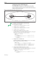
This example (Figure 22 on page 121) is a simple network of two routers
connected together, each with its own local area network. The routers all
belong to a single class B network 172.31.0.0, which has further been subnetted
using the subnet mask 255.255.255.0.
Figure 22: .A basic OSPF network with an addressless PPP link.
To configure a basic OSPF network follow these steps
The following steps are required:
1. Configure the PPP and Ethernet interfaces on router 1.
2. Configure router 1 as an OSPF router.
3. Configure the PPP and Ethernet interfaces on router 2.
4. Configure router 2 as an OSPF router.
1. Configure the PPP and Ethernet interfaces on router 1.
To create IP interfaces to use the PPP and Ethernet interfaces, and assign an
OSPF metric to each IP interface, enter the command:
CREATE PPP=0 OVER=SYN0
ENABLE IP
ADD IP INTERFACE=PPP0 IP=172.31.2.1 MASK=255.255.255.0
OSPFMETRIC=1
ADD IP INTERFACE=ETH0 IP=172.31.1.1 MASK=255.255.255.0
OSPFMETRIC=1
2. Configure router 1 as an OSPF router.
To create an OSPF area, assign the IP interfaces to the area, and configure
OSPF routing parameters, enter the commands:
ENABLE OSPF
ADD OSPF AREA=0.0.0.1 AUTHENTICATION=PASSWORD
ADD OSPF RANGE=172.31.0.0 AREA=0.0.0.1 MASK=255.255.0.0
ADD OSPF INTERFACE=ETH0 AREA=0.0.0.1 PASSWORD=asecret
ADD OSPF INTERFACE=PPP0 AREA=0.0.0.1 PASSWORD=bsecret
3. Configure the PPP and Ethernet interfaces on router 2.
To create IP interfaces to use the PPP and Ethernet interfaces, and assign an
OSPF metric to each IP interface, enter the command:
CREATE PPP=0 OVER=SYN0
ENABLE IP
ADD IP INTERFACE=PPP0 IP=172.31.2.2 MASK=255.255.255.0
OSPFMETRIC=1
UGOSPF1_R
LAN
LAN
Point-to-Point link
172.31.2.1
172.31.2.2
172.31.108.10
Router 2
Router 1
172.31.1.1
Area 1