ExpressCard Fast Ethernet Fiber (SC) Module AT-2812FX Installation and User’s Guide 613-001225 Rev.
Copyright 2010 Allied Telesis, Inc. All rights reserved. No part of this publication may be reproduced without prior written permission from Allied Telesis, Inc. Microsoft and Internet Explorer are registered trademarks of Microsoft Corporation. Netscape Navigator is a registered trademark of Netscape Communications Corporation. All other product names, company names, logos or other designations mentioned herein are trademarks or registered trademarks of their respective owners. Allied Telesis, Inc.
Electrical Safety and Emissions Standards This product meets the following standards. U.S. Federal Communications Commission Declaration of Conformity Manufacturer Name: Allied Telesis, Inc. Declares that the product: ExpressCard Fast Ethernet Fiber (SC) Module Model Numbers: AT-2812FX This product complies with FCC Part 15B, Class B Limits: This device complies with part 15 of the FCC Rules.
Translated Safety Statements Important: The indicates that a translation of the safety statement is available in a PDF document titled “Translated Safety Statements” posted on the Allied Telesis website at: www.alliedtelesis.com/support/software/.
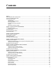
Contents Preface ................................................................................................................................................................................11 Safety Symbols Used in this Document................................................................................................................................12 Where to Find Web-based Guides .....................................................................................................................
Contents Checksum Offload .........................................................................................................................................................71 VLAN ID.........................................................................................................................................................................72 Wake Up Capabilities ..................................................................................................................................
Figures Figure 1. AT-2812FX Module ..............................................................................................................................................16 Figure 2. AT-2812FX LED ...................................................................................................................................................20 Figure 3. Selecting the PCI ExpressCard Slot.................................................................................................................
Figures 8
Tables Table 1: Safety Symbols ......................................................................................................................................................12 Table 2: Fiber Optic Port 100 LED Status ...........................................................................................................................
Tables 10
Preface This guide contains instructions on how to install the AT-2812FX ExpressCard Fast Ethernet Fiber (SC) Module on a laptop computer. It also describes how to install the driver software on the AT-2812FX module and configure the driver software. The Windows Vista, Windows XP, and Windows 7 Operating Systems driver software is described in this manual. Additional operating systems are available on the Allied Telesis website on the software and document download site for this adapter.
Preface Safety Symbols Used in this Document This document uses the safety symbols defined in Table 1. Table 1. Safety Symbols Symbol 12 Meaning Description Caution Performing or omitting a specific action may result in equipment damage or loss of data. Warning Performing or omitting a specific action may result in electrical shock.
AT-2812FX ExpressCard Fast Ethernet Fiber (SC) Module Installation and User’s Guide Where to Find Web-based Guides The installation and user guides for all Allied Telesis products are available in portable document format (PDF) on our web site at www.alliedtelesis.com/support/software/. You can view the documents online or download them onto a local workstation or server.
Preface Contacting Allied Telesis This section provides Allied Telesis contact information for technical support as well as sales or corporate information. Online Support You can request technical support online by accessing the Allied Telesis Knowledge Base: www.alliedtelesis.com/support/kb.aspx. You can use the Knowledge Base to submit questions to our technical support staff and review answers to previously asked questions.
Chapter 1 Introducing the AT-2812FX Module This chapter provides an introduction to the Allied Telesis AT-2812FX ExpressCard Fast Ethernet Fiber (SC) Module and contains the following sections: “Functional Description” on page 16 “Hardware Features” on page 18 “Supported Operating Systems” on page 19 “Physical Description” on page 20 15
Chapter 1: Introducing the AT-2812FX Module Functional Description The AT-2812FX is a highly integrated Fiber Fast Ethernet ExpressCard/34 module based on Broadcom’s BCM5761S chipset. It provides an PCI ExpressCard interface with SC connections to multimode fiber. Using fiber optic cabling and a connector that meets 62.5/125 µm or 50/ 125 µm multimode specifications, the AT-2812FX module connects a laptop computer to a Fast Ethernet network.
AT-2812FX ExpressCard Fast Ethernet Fiber (SC) Module Installation and User’s Guide Note The AT-2812FX module is not shipped with a software driver CD. To download new driver software for the AT-2812FX module, see “Management Software Updates” on page 14. Inform your network supplier of any missing or damaged items. If you need to return the module, you must pack it in the original (or equivalent) packing material or the warranty will be voided. See “Returning Products” on page 14.
Chapter 1: Introducing the AT-2812FX Module Hardware Features The following list of hardware features for the AT-2812FX module applies to all of the supported operating systems: 18 One 100BASE-FX port with SC multi-mode fiber connector Full and half duplex Media Access Control (MAC) IPv4 and IPv6 Large Send Offload and Checksum Offload (LSO/TCO) Receive Side Scaling (RSS) for multi-core client processors PCI-ExpressCard Interface Wake on LAN (WOL) support that meets the APCI requir
AT-2812FX ExpressCard Fast Ethernet Fiber (SC) Module Installation and User’s Guide Supported Operating Systems The following operating systems are described in this manual: Windows Vista Windows XP Windows 7 Additional operating systems are available on the following Allied Telesis website: www.alliedtelesis.com/support/software/.
Chapter 1: Introducing the AT-2812FX Module Physical Description This section provides descriptions of the AT-2812FX faceplate and the LED. The faceplate on the AT-2812FX module has one fiber port that provides two fiber optic connectors for attaching the module to a compatible link partner (one transmitting and one receiving). LI N K/ AC T The AT-2812FX module has one LED, as shown in Figure 2. See Table 1 for a description of the LED operating status. 1757 Figure 2. AT-2812FX LED Table 1.
Chapter 2 Installing the Hardware This chapter contains the following sections: “Reviewing Safety Precautions” on page 22 “Pre-Installation Checklist” on page 24 “Installing the Module” on page 25 “Connecting the Network Cables” on page 29 21
Chapter 2: Installing the Hardware Reviewing Safety Precautions Please review the following safety precautions before you begin to install a module. Note The indicates that a translation of the safety statement is available in a PDF document titled “Translated Safety Statements” posted on the Allied Telesis website at www.alliedtelesis.com/ support/software/. Warning This is a “Class 1 LED product”. L1 Warning Do not stare into the laser beam.
AT-2812FX ExpressCard Fast Ethernet Fiber (SC) Module Installation and User’s Guide Warning The module is being installed in a system that operates with voltages that can be lethal. Before you remove the cover of your system, you must observe the following precautions to protect yourself and to prevent damage to the system components. - Remove any metallic objects or jewelry from your hands and wrists. - Make sure to use only insulated or nonconducting tools.
Chapter 2: Installing the Hardware Pre-Installation Checklist Before you install the module, check the following list: 1. Verify that your laptop is using the latest BIOS. If you downloaded the module software from the Allied Telesis support website, record the path to where the module driver files reside on your system. 2. If your laptop is active, shut it down. 3. When the system shut down is complete, power OFF and unplug your system. 4.
AT-2812FX ExpressCard Fast Ethernet Fiber (SC) Module Installation and User’s Guide Installing the Module The following instructions describe how to install the AT-2812FX module in a laptop equipped with a PCI ExpressCard interface slot. This procedure applies to laptops with either 34 mm or 54 mm interface slots. For laptop computers, the 54 mm interface is the more common interface. Therefore, the installation illustrations in this manual use the 54 mm interface.
Chapter 2: Installing the Hardware 1758 Figure 3. Selecting the PCI ExpressCard Slot 3. Use a pen and press the button toward the laptop and to the left. See Figure 4. The button pops out along with the plate. See Figure 5 on page 27. 1710 Figure 4.
AT-2812FX ExpressCard Fast Ethernet Fiber (SC) Module Installation and User’s Guide 1711 Figure 5. Removing the Faceplate from the PCI ExpressCard Slot 4. Remove the plate from the laptop. See Figure 6. Keep the plate in a safe place. You may need it for future use. 1712 Figure 6.
Chapter 2: Installing the Hardware 5. For the 54 mm ExpressCard slot, align the module to the left side of the slot. See Figure 7. LI N K/ AC T For laptops with the 34 mm ExpressCard slot, the module fits snugly into the slot. 1713 Figure 7. Inserting the Module 6. Applying even pressure at both corners of the module, push the module until it is firmly seated in the PCI ExpressCard slot. Caution Do not use excessive force when seating the module, because this may damage the system or the module.
AT-2812FX ExpressCard Fast Ethernet Fiber (SC) Module Installation and User’s Guide Connecting the Network Cables The AT-2812FX module has two fiber optic connectors (transmit and receive) for attaching the system to a compatible link partner, or an IEEE 802.3z compliant Fast Ethernet switch. The module requires a fiber optic cable. For specifications for this cable, see the AT-2812FX module data sheet or Appendix A, “Specifications” on page 75.
Chapter 2: Installing the Hardware 30
Chapter 3 Installing the Vista Driver Software This chapter describes how to install and update the Vista driver software for the AT-2812FX module. The installation procedure is identical for the both the Vista 32-bit and 64-bit operating systems. This chapter contains the following sections: “Installing the Driver Software” on page 32 “Uninstalling the Driver Software” on page 43 Note To set Advanced Properties, see Chapter 6, “Setting Advanced Properties” on page 61.
Chapter 3: Installing the Vista Driver Software Installing the Driver Software After you install an Allied Telesis AT-2812FX module in your laptop computer, the system detects the new hardware automatically when the Windows Vista Operating system first boots up. Shortly after you log in, you are prompted to install the driver software for the module. To install or update the driver software, you must have administrative privileges.
AT-2812FX ExpressCard Fast Ethernet Fiber (SC) Module Installation and User’s Guide Figure 8. Found New Hardware Window 3. From the Found New Hardware window, select Locate and install driver software (recommended). The Found New Hardware - Ethernet Controller window is displayed. See Figure 9 on page 34.
Chapter 3: Installing the Vista Driver Software Figure 9. Found New Hardware - Ethernet Controller Window 4. From the Found New Hardware - Ethernet Controller window, select Don’t search online. The Found New Hardware - Ethernet Controller window is displayed. See Figure 10 on page 35.
AT-2812FX ExpressCard Fast Ethernet Fiber (SC) Module Installation and User’s Guide Figure 10. Found New Hardware - Ethernet Controller Window 5. Click I don’t have the disc. Show me other options. Note The AT-2812FX module is not shipped with a CD. The Found New Hardware - Ethernet Controller Windows Couldn’t Find Driver window is displayed. See Figure 11 on page 36.
Chapter 3: Installing the Vista Driver Software Figure 11. Found New Hardware - Ethernet Controller Windows Couldn’t Find Driver Window 6. Select Browse my computer for drive software (advanced). Select the directory where the AT-2812FX driver is located. You recorded this location during the pre-installation checklist. See “PreInstallation Checklist” on page 24.
AT-2812FX ExpressCard Fast Ethernet Fiber (SC) Module Installation and User’s Guide The following window is displayed: Figure 12. Found New Hardware - Ethernet Controller Browse for Driver Software Window Then a confirmation page is displayed. See Figure 13 on page 38.
Chapter 3: Installing the Vista Driver Software Figure 13. Update Driver Software - Allied Telesis AT-2812FX 100FX Fiber Window 7. Confirm that the AT-2812FX module has been installed successfully by opening the Device Manager. To open the Device Manager, see “Selecting the Device Manager” on page 39.
AT-2812FX ExpressCard Fast Ethernet Fiber (SC) Module Installation and User’s Guide Selecting the Device Manager To select the Device Manager in the Windows Vista Operating System, do the following: 1. From the Start menu, select Settings and then the Control Panel. See Figure 14. Figure 14.
Chapter 3: Installing the Vista Driver Software 2. From the Control Panel, select Administrative Tools. The Administrative Tools window is displayed. See Figure 15. Figure 15. Administrative Tools Window 3. From the Administrative Tools window, select Computer Management (local). The Computer Management window is displayed. See Figure 16 on page 41.
AT-2812FX ExpressCard Fast Ethernet Fiber (SC) Module Installation and User’s Guide Figure 16. Computer Management Window 4. From the Computer Management Window, select Device Manager in the left panel. The Device Manager window is displayed. See Figure 17 on page 42.
Chapter 3: Installing the Vista Driver Software On the Device Manager window, “Allied Telesis AT-2812FX Fiber” is listed under “Network adapters.” Figure 17.
AT-2812FX ExpressCard Fast Ethernet Fiber (SC) Module Installation and User’s Guide Uninstalling the Driver Software The procedure in this section describes how to uninstall the driver software. Note You must have Administrator privileges to remove the driver software. Caution Before uninstalling the Allied Telesis device, capture all of the Advanced Property settings because the properties are lost during the uninstall process. To uninstall the driver software from your system, do the following: 1.
Chapter 3: Installing the Vista Driver Software 44
Chapter 4 Installing the Windows XP Driver Software This chapter describes how to install the Windows XP driver software on the AT-2812FX module. This chapter covers the following topics: “Installing the Driver Software” on page 46 “Uninstalling the Driver Software” on page 52 Note To set Advanced Properties, see Chapter 6, “Setting Advanced Properties” on page 61.
Chapter 4: Installing the Windows XP Driver Software Installing the Driver Software After you install an Allied Telesis AT-2812FX module in your laptop, the system detects the new hardware and creates an entry in the Device Manager when the Windows XP Operating system first boots up. Shortly after you log in, you need to install the driver software for the AT-2812FX module. To install or update the driver software, you must have administrative privileges.
AT-2812FX ExpressCard Fast Ethernet Fiber (SC) Module Installation and User’s Guide Selecting the Device Manager Window You use the Device Manager window to both install and uninstall the Windows XP driver software for the AT-2812FX adapter. To open the Device Manager window on a Windows XP Operating System, do the following: 1. Start a Windows XP system and log in. 2. On the desktop, right click My Computer. The My Computer window opens. 3. Select Properties from the menu.
Chapter 4: Installing the Windows XP Driver Software The Hardware Tab is shown in Figure 19. Figure 19. Hardware Tab 5. Click Device Manager. The Device Manager window is shown in Figure 20 on page 49.
AT-2812FX ExpressCard Fast Ethernet Fiber (SC) Module Installation and User’s Guide Figure 20. Device Manager Window Updating the Windows XP Driver Software To update the adapter software on a Windows XP Operating System, do the following: 1. Start a Windows XP system and log in. You must have Administrator privileges to update the driver software. 2. Open the Device Manager. For instructions, see “Selecting the Device Manager Window” on page 47. 3.
Chapter 4: Installing the Windows XP Driver Software Figure 21. Welcome to Hardware Update Wizard Window 5. Click No, not this time to copy the driver software from your system. You recorded the location of the driver software in the “Pre-Installation Checklist” on page 24. 6. Click Next. The Second New Found Hardware Wizard Window opens, as shown in Figure 22. Figure 22.
AT-2812FX ExpressCard Fast Ethernet Fiber (SC) Module Installation and User’s Guide 7. Click Install from a list or specific location (Advanced). 8. Click Next. 9. When you are prompted to specify the location of the drive, click Browse and locate the path of the drivers. Update all adapters by repeating the above steps for each device. After driver software installation is complete, you are ready to modify the configuration properties. See “Uninstalling the Driver Software” on page 52.
Chapter 4: Installing the Windows XP Driver Software Uninstalling the Driver Software To uninstall the Windows XP driver software from your laptop, do the following: Note You must have Administrator privileges to remove the driver software. Caution Before uninstalling the Allied Telesis device, be sure to capture all of the Advanced Property settings because the properties are lost during the uninstall process. 1. Start Windows XP and log in. 2. Open the Device Manager.
Chapter 5 Installing the Windows 7 Driver Software This chapter describes how to install the Windows 7 driver software on the AT-2812FX module. The installation and configuration procedure are identical for the both the 32-bit and 64-bit Windows 7 Operating Systems. This chapter contains the following sections: “Installing the Driver Software” on page 54 “Uninstalling the Driver Software” on page 60 Note To set Advanced Properties, see Chapter 6, “Setting Advanced Properties” on page 61.
Chapter 5: Installing the Windows 7 Driver Software Installing the Driver Software After you install an Allied Telesis AT-2812FX module in your laptop, the system detects the new hardware and creates an entry in the Device Manager when the Windows 7 Operating system first boots up. Shortly after you log in, you need to install the driver software for the AT-2812FX module. To install or update the driver software, you must have administrative privileges.
AT-2812FX ExpressCard Fast Ethernet Fiber (SC) Module Installation and User’s Guide 2. Select Computer on the right side of the menu. The Computer window is displayed. See Figure 24. Figure 24. Computer Window 3. Select System properties at the top of the page. The Control Panel > System and Security > System Window is displayed. See Figure 25 on page 56.
Chapter 5: Installing the Windows 7 Driver Software Figure 25. Control Panel > System and Security > System Window 4. Select Device Manager from the bookmarks on the left side of the window to confirm that the AT-2812FX module has been installed successfully. The Device Manager window is displayed. See Figure 26 on page 57. On the Device Manager window, “Allied Telesis AT-2812FX Fiber Ethernet” is listed under “Network adapters.
AT-2812FX ExpressCard Fast Ethernet Fiber (SC) Module Installation and User’s Guide Figure 26. Device Manager Window Installing the Windows 7 Driver Software To install the Windows 7 Operating System driver software, do the following: Note The module must be physically installed in your system before you install the driver software. See Chapter 2, “Installing the Hardware” on page 21 for instructions. 1. Start a Windows 7 Operating system and log in. 2. Open the Device Manager window.
Chapter 5: Installing the Windows 7 Driver Software 3. On the Device Manager Window, right click Ethernet Controller and select Update Driver Software. See Figure 27. Figure 27. Device Manager Window: Ethernet Controller The Update Driver Software - Ethernet Controller Window is displayed. See Figure 28. Figure 28. Update Driver Software - Ethernet Controller Window 4. Click Browse my computer for driver software. The Update Driver Software - Ethernet Controller window is displayed.
AT-2812FX ExpressCard Fast Ethernet Fiber (SC) Module Installation and User’s Guide 5. Browse your computer for the location of the driver software. See Figure 29. Figure 29. Update Driver Software - Ethernet Controller Window: Browse for driver software 6. Click Browse. A confirmation message is displayed. See Figure 30. Figure 30.
Chapter 5: Installing the Windows 7 Driver Software Uninstalling the Driver Software Before physically removing a module from your system, you need to uninstall the driver software first. The procedure in this section describes how to uninstall the driver software. Note You must have Administrator privileges to remove the driver software.
Chapter 6 Setting Advanced Properties For the Windows Vista, Windows XP, and Windows 7 Operating System software, you access the Advanced Properties through the Device Manager. Accessing the Device Manager is slightly different for all 3 operating systems.
Chapter 6: Setting Advanced Properties Opening Advanced Properties In most cases, the default property values are appropriate although you can change any of the available options to meet the requirements of your system. You must have Administrator privileges to modify the driver software.
AT-2812FX ExpressCard Fast Ethernet Fiber (SC) Module Installation and User’s Guide Flow Control The Flow Control property allows you to enable or disable the receipt or transmission of PAUSE frames which enable the adapter and the switch to control the transmit rate. The port side that receives the PAUSE frame momentarily stops transmitting. The recommended selection is Disable, which configures the adapter to ignore PAUSE frames. By default, the Flow Control property is disabled.
Chapter 6: Setting Advanced Properties The Advanced tab for the AT-2812FX adapter is shown in Figure 31. Figure 31.
AT-2812FX ExpressCard Fast Ethernet Fiber (SC) Module Installation and User’s Guide Interrupt Moderation Interrupt moderation enables adaptive interrupt coalescing, which limits the rate of interrupt to the CPU during packet transmission and packet reception. The disabled option allows one interrupt for every packet transmission and packet reception. The default value is Enabled. To change the Interrupt Moderation setting, do the following: 1. Access the Device Manger for your operating system.
Chapter 6: Setting Advanced Properties Microsoft’s Technet website, www.technet.microsoft.com, offers several technical publications and online seminars that describe Vista’s advanced IPSec and Firewall features as well as their implementation. These topics are beyond the scope of this chapter. Instead, Allied Telesis recommends that you consult Technet for additional information. By default, the IPSec Offload property is set to Disabled.
AT-2812FX ExpressCard Fast Ethernet Fiber (SC) Module Installation and User’s Guide Large Send Offload Property Normally, the protocol stack performs TCP segmentation. When you enable the Large Send Offload property, the network adapter does the TCP segmentation. There are several Large Send Offload properties to choose from, depending on the TCP/IP version you are using on your PC. You can select IPV4, IPV4 version 2, or IPv6 version 2. By default, the Large Send Offload Property is disabled.
Chapter 6: Setting Advanced Properties Network Address The Network Address is a user-defined address that is used to replace the MAC address that was originally assigned to the adapter. The network address consists of a 12-digit hexadecimal number. To change the Locally Administered Address property, do the following: 1. Access the Device Manger for your operating system. To access the Windows XP Device Manager, see “Selecting the Device Manager Window” on page 47.
AT-2812FX ExpressCard Fast Ethernet Fiber (SC) Module Installation and User’s Guide Priority & VLAN Priority allows you to prioritize traffic or limit bandwidth instead of treating all traffic in the same manner. A Virtual Local Area Network (VLAN) is a logical area network that extends beyond a traditional LAN to a group of logical LANs. By default, this property is set to Priority & VLAN Enabled. To set the port priority and assign a VLAN ID, do the following: 1.
Chapter 6: Setting Advanced Properties Receive Side Scaling The Receive Side Scaling (RSS) feature configures RSS queues from 1 to 4. The available options are RSS 1 Queue, RSS 2 Queue, and RSS 4 Queue. By default, RSS is set to Enabled. To set Receive Side Scaling, do the following: 1. Access the Device Manger for your operating system. To access the Windows XP Device Manager, see “Selecting the Device Manager Window” on page 47.
AT-2812FX ExpressCard Fast Ethernet Fiber (SC) Module Installation and User’s Guide To access the Windows 7 Device Manager, see “Selecting the Device Manager Window” on page 54. 2. Click the Advanced tab. The Advanced tab is shown in Figure 31 on page 64. 3. From the Property list on the Advanced tab, select “Speed & Duplex.” 4. In the Value list on the Advanced tab, select one of the following: 100 Mb Full 100 Mb Half 5. Click OK. 6. If prompted to restart your computer, click Yes.
Chapter 6: Setting Advanced Properties 4. From the Value list on the Advanced tab, select one of the following: None - Disables checksum offloading. Rx TCP/IP Checksum - Enables receive TCP, IP, and UDP checksum offloading. Tx TCP/IP Checksum - Enables transmit TCP, IP, and UDP checksum offloading. Tx/Rx TCP/IP Checksum (default) - Enables transmit and receive TCP, IP, and UDP checksum offloading. 5. Click OK. 6. If prompted to restart your computer, click Yes.
AT-2812FX ExpressCard Fast Ethernet Fiber (SC) Module Installation and User’s Guide 5. Click OK. 6. If prompted to restart your computer, click Yes. Although it is not necessary to reboot the system for new adapter properties to take effect, rebooting is recommended to reinitialize all registers. 7. Verify that the port LED operates as described in “Physical Description” on page 20.
Chapter 6: Setting Advanced Properties WOL Speed 74 The WOL Speed property sets the speed at which the network adapter connects to the network while the network adapter is in Wake on LAN (WOL) mode. The default speed for WOL mode is 100 Mb. In addition, this is the only speed available for the AT-2812FX module.
Appendix A Specifications Physical Specifications This section provides the dimensions and weight of the module. Dimensions: 13.7 cm x 3.4 cm (5.4 in. x 1.3 in.) Weight: 45.36 g (.10 lbs.
Appendix A: Specifications Performance Specification The following performance specification apply to the AT-2812FX module: MTBF 3,210,000 hours Operating Specifications The following operating specifications apply to the AT-2812FX module: 76 Output Optical Power: -20 dBm minimum to -14 dBm maximum Input Optical Power: -31 dBm to -11 dBm maximum Receive Sensitivity: -12.5 dBm with 62.5 um fiber or -13.
Appendix B Cleaning Fiber Optic Connectors The fiber optic connector consists of a fiber optic plug and its adapter. The end of the fiber optic cable is held in the core of the ferrule in the plug. Light signals are transmitted through the core of the fiber. Even minor smudges or dirt on the end face of the fiber, completely invisible to the naked eye, can disrupt light transmission and lead to failure of the component or of the entire system.
Appendix B: Cleaning Fiber Optic Connectors Using a Cartridge-Type Cleaner PUSH OPEN Di re c A PEng TAWipi tion Fiber optic cartridge cleaners are available from many vendors and are typically called “cartridge cleaners,” as shown in Figure 34. Figure 34. Cartridge Cleaner Note Do not use compressed air or aerosol air to clean a fiber optic connector. To clean a fiber optic connector using a cartridge cleaner, do the following. 1.
AT-2812FX ExpressCard Fast Ethernet Fiber (SC) Module Installation and User’s Guide Note Rub the ferrule tip on the cleaning surface in one direction only. 3. When you reach the end of the cleaning surface, pick up the ferrule tip, rotate and place it at the top and rub downwards at least 2 times. Caution Failing to pick up the ferrule tip when you reach the bottom of the cleaning surface can result in static electricity that can damage the fiber optic cable. 4. If desired, repeat steps 3 and 4. 5.
Appendix B: Cleaning Fiber Optic Connectors Using a Swab Specially treated swabs (stick cleaners) are available for cleaning inside connector adapters or hard-to-reach ferrule tips. These swabs, often referred to as “lint free” or “alcohol free” swabs, are available from many vendors, as shown in Figure 36. Stick cleaners are available in both 2.5 mm and 1.25 mm sizes for use on SC and MU connectors respectively. Note NEVER use a household cotton swab and/or alcohol to clean a fiber optic connector.
AT-2812FX ExpressCard Fast Ethernet Fiber (SC) Module Installation and User’s Guide 3. If a fiber inspection scope is available, use the scope to inspect the connector to make sure that it is clean and to check for scratches, pits, or other problems that may affect performance. Note Always keep a dust cap on a fiber optic cable when it is not in use. Warning Do not stare into the laser beam. L2 Warning Do not look directly at the cable ends or inspect the cable ends with an optical lens.
Appendix B: Cleaning Fiber Optic Connectors 82