Gigabit Ethernet Network Adapters AT-2916T AT-2971SX AT-2971T Installation Guide 613-000767 Rev.
Copyright © 2007 Allied Telesis, Inc. All rights reserved. No part of this publication may be reproduced without prior written permission from Allied Telesis, Inc. Allied Telesis and the Allied Telesis logo are trademarks of Allied Telesis, Inc. Microsoft and Internet Explorer are registered trademarks of Microsoft Corporation. Netscape Navigator is a registered trademark of Netscape Communications Corporation.
Electrical Safety and Emissions Standards This product meets the following standards. Federal Communications Commission Interference Statement Declaration of Conformity Manufacturer Name: Allied Telesis, Inc. Declares that the product: Gigabit Ethernet Adapters Model Numbers: AT-2916T, AT-2971T, AT-2971SX This equipment has been tested and found to comply with the limits for a Class B digital device, pursuant to Part 15 of FCC Rules.
Electrical Safety EN60950 (TUV), UL 60950 (CULUS) Laser Safety EN60825 Translated Safety Statements Important: The indicates that a translation of the safety statement is available in a PDF document titled “Translated Safety Statements” (613-000405) on the Allied Telesis website at www.alliedtelesis.com.
Contents Preface ..................................................................................................................................................................................9 Safety Symbols Used in this Document................................................................................................................................10 Where to Find Web-based Guides ....................................................................................................................
Contents 6
Figures Figure 1. Figure 2. Figure 3. Figure 4. Figure 5. Figure 6. Figure 7. AT-2916T Gigabit Ethernet Adapter .....................................................................................................................16 AT-2971SX Gigabit Ethernet Adapter ..................................................................................................................17 AT-2971T Gigabit Ethernet Adapter ............................................................................................
Figures 8
Preface This guide contains instructions on how to install the AT-29xx Series Gigabit Ethernet network adapters.
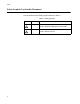
Preface Safety Symbols Used in this Document This document uses the safety symbols defined in Table 1. Table 1. Safety Symbols Symbol 10 Meaning Description Caution Performing or omitting a specific action may result in equipment damage or loss of data. Warning Performing or omitting a specific action may result in electrical shock.
AT-29xx Series Gigabit Ethernet Network Adapters Installation Guide Where to Find Web-based Guides The installation and user guides for all Allied Telesis products are available in portable document format (PDF) on our web site at www.alliedtelesis.com. You can view the documents online or download them onto a local workstation or server.
Preface Contacting Allied Telesis This section provides Allied Telesis contact information for technical support as well as sales and corporate information. Online Support You can request technical support online by accessing the Allied Telesis Knowledge Base: www.alliedtelesis.com/support/kb.aspx. You can use the Knowledge Base to submit questions to our technical support staff and review answers to previously asked questions.
Chapter 1 Introduction to the AT-29xx Series Gigabit Ethernet Network Adapters This chapter provides an introduction to the Allied Telesis AT-29xx Series Gigabit Ethernet network adapters and contains the following sections: “Functional Description” on page 14 “Features” on page 15 “LEDs” on page 16 13
Chapter 1: Introduction to the AT-29xx Series Gigabit Ethernet Network Adapters Functional Description The AT-29xx Series Gigabit Ethernet network adapters target the increased congestion experienced at the backbone and server in today’s networks and it provides a future upgrade path for high-end workstations that require more bandwidth than Fast Ethernet can provide. The adapter connects a PCI compliant server or workstation to a Gigabit Ethernet network.
AT-29xx Series Gigabit Ethernet Adapters Installation Guide Features Following is a list of the AT-29xx Series Gigabit Ethernet network adapters features for all of the supported operating systems: TCP, UDP, and IP checksum calculation Jumbo frames (9 KB) TCP segmentation (large send off-load) PXE support Advanced power management/wake on LAN Flow Control (IEEE 802.
Chapter 1: Introduction to the AT-29xx Series Gigabit Ethernet Network Adapters LEDs Each adapter has a set of LEDs as shown in the following illustrations and tables: AT-2916T “AT-2916T,” next “AT-2971SX” on page 17 “AT-2971T” on page 18 The AT-2916T Gigabit Ethernet adapter has one copper port and five LEDs, as shown in Figure 1 and described in Table 1. FULL DUPLEX 10 L I N 1000 K 100 ACT 1250 Figure 1. AT-2916T Gigabit Ethernet Adapter \ Table 1.
AT-29xx Series Gigabit Ethernet Adapters Installation Guide Table 1. AT-2916T LEDs (Continued) LED 100 1000 ACT AT-2971SX Color Green Green Green State Description On A valid link has been established at 100 Mbps. Off No valid link at 100 Mbps. On A valid link has been established at 1000 Mbps. Off No valid link at 1000 Mbps. On The adapter is receiving or transmitting data. Off The adapter is not receiving or transmitting data.
Chapter 1: Introduction to the AT-29xx Series Gigabit Ethernet Network Adapters Table 2. AT-2971SX LEDs LED Color 1000/LINK ACT AT-2971T State Green Green Description On A valid link has been established at 1000 Mbps. Off No valid link at 1000 Mbps. On The adapter is receiving or transmitting data. Off The adapter is not receiving or transmitting data. The AT-2971T Gigabit Ethernet adapter has one copper port and four LEDs, as shown in Figure 3 and described in Table 3.
AT-29xx Series Gigabit Ethernet Adapters Installation Guide Table 3. AT-2971T LEDs (Continued) LED 100 1000 ACT Color Green Green Green State Description Off No valid link at 10 Mbps. On A valid link has been established at 100 Mbps. Off No valid link at 100 Mbps. On A valid link has been established at 1000 Mbps. Off No valid link at 1000 Mbps. On The adapter is receiving or transmitting data. Off The adapter is not receiving or transmitting data.
Chapter 1: Introduction to the AT-29xx Series Gigabit Ethernet Network Adapters 20
Chapter 2 Installing the Hardware This chapter contains the following sections: “Reviewing Safety Precautions” on page 22 “Pre-Installation Checklist” on page 24 “Installing a Network Adapter Card” on page 25 “Connecting the Network Cables” on page 29 21
Chapter 2: Installing the Hardware Reviewing Safety Precautions Please review the following safety precautions before you begin to install the network adapter card. Note The indicates that a translation of the safety statement is available in a PDF document titled “Translated Safety Statements” (613-000405) on the Allied Telesis website at www.alliedtelesis.com. Warning This is a “Class 1 LED product”. L1 Warning Do not stare into the laser beam.
AT-29xx Series Gigabit Ethernet Adapters Installation Guide wrists. - Use only insulated or nonconducting tools. - Verify that the system is powered OFF and unplugged before accessing internal components. - Installation or removal of adapters must be performed in a staticfree environment. The use of a properly grounded wrist strap or other personal antistatic devices and an antistatic mat is strongly recommended.
Chapter 2: Installing the Hardware Pre-Installation Checklist 1. Check that your system has an appropriate open PCI slot. 2. Verify that your system is using the latest BIOS. 3. If your system is active, shut it down. 4. When system shut down is complete, power OFF and unplug your system. 5. Holding the adapter card by the edges, remove it from its shipping package and place it on an antistatic surface. 6. Check the adapter for visible signs of damage, particularly on the card’s edge connector.
AT-29xx Series Gigabit Ethernet Adapters Installation Guide Installing a Network Adapter Card The following instructions apply to installing the Gigabit Ethernet adapter in most systems. Refer to the manuals that were supplied with your system for details about performing these tasks on your particular system. To install the network adapter card, perform the following procedure: 1. Review the “Pre-Installation Checklist” on page 24 and “Reviewing Safety Precautions” on page 22.
Chapter 2: Installing the Hardware 3. Select an empty, non-shared PCI slot and remove the faceplate. Keep the faceplate in a safe place. You may need it for future use. See Figure 5. Figure 5. Removing the Faceplate From PCI Slot Note If you cannot locate or know how to find an appropriate PCI slot, refer to the documentation that came with your system. 4. Remove the network adapter card from the shipping package and store the packaging material in a safe location.
AT-29xx Series Gigabit Ethernet Adapters Installation Guide Make sure the card is securely seated. See Figure 6. Figure 6. Inserting the Network Adapter Card Note The connector dock in a 32-bit PCI slot is shorter than in a 64-bit PCI slot. Although the AT-29xx series adapter is designed to fit in either slot type, when installed in a 32-bit PCI slot, part of the adapter’s connector edge remains undocked. This is part of normal operation.
Chapter 2: Installing the Hardware 6. Secure the network adapter card to the chassis with a Phillips-head screw (not provided) as shown in Figure 7. Figure 7. Securing the Adapter Card 7. Replace the system’s cover and secure it with the screws removed in Step 2. 8. Disconnect any personal antistatic devices. 9. Power the system on. Once the system returns to proper operation, the adapter hardware is fully installed. Next, connect the network cables. See “Connecting the Network Cables” on page 29.
AT-29xx Series Gigabit Ethernet Adapters Installation Guide Connecting the Network Cables All the fiber Gigabit Ethernet network adapters have two fiber optic connectors for attaching the system to a compatible link partner, or an IEEE 802.3z compliant gigabit switch. After connecting the system to the network and power is supplied, the adapter performs auto-negotiation and attempts to establish the connection at 1000 Mbps full-duplex only.
Chapter 2: Installing the Hardware 30
Appendix A Specifications Physical Specifications Dimensions: AT-2916T : 11.99 cm x 5.29 cm (4.72 in. x 2.08 in.) AT-2971T : 16.76 cm x 5.73 cm (6.6 in. x 2.26in.) AT-2971SX : 16.76 cm x 6.44 cm (6.6 in. x 2.54 in.) Weight: AT-2916T : 65 g (.14 lbs.) AT-2971T : 72 g (.16 lbs.) AT-2971SX : 92 g (.20 lbs.
Appendix A: Specifications Performance Specifications PCI clock: 33/66 MHz max PCI-X clock: 66 to 133 MHz PCI or PCI-X Data/Address: AT-2916T AT-2971T AT-2971SX 32-bit 32-bit and 64-bit 32-bit and 64-bit Operating Specifications 32 Output Optical Power: -9.5 dBm minimum to -4 dBm maximum Input Optical Power: -18 dBm to 0 dBm maximum Receive Sensitivity: -12.5 dBm with 62.5 um fiber or -13.