Release Note Software Release 2.6.1 For AT-8900 Series Switches Introduction ...................................................................................................... 3 Key Hardware Features of the AT-8900 Series Switch ........................................ 4 Power Supply Units (PSUs) .......................................................................... 4 PSU LEDs on AT-8900 Switches ................................................................... 5 SFP Transceivers ...............
Software Release 2.6.1 2 Overlapping VLANs Belonging to Multiple Spanning Tree Instances ................. The Ingress and Egress Rules for Layer 2 Switching .......................................... The Ingress Rules ...................................................................................... The Egress Rules ....................................................................................... Classifier-Based Packet Filters ...................................................................
Software Release 2.6.1 3 Introduction Allied Telesyn announces the release of Software Release 2.6.1 for the AT-8900 Series switches. The AT-8900 Series Switches are a new series of high-end Layer 3+ switches built to meet the needs of high performance network services. The AT-8900 Series Switches are currently represented by the AT-8948 Multi-layer Fast Ethernet Switch. The files included in this software release are shown in the table below. Table 1: File names for Software Release 2.6.
Release Note Key Hardware Features of the AT-8900 Series Switch Key hardware features of the AT-8948 Multi-layer Fast Ethernet Switch are: • 1RU form factor • dual, hot-swappable, load-sharing power supply units (AC or DC options) accessible at the rear of the switch chassis • front to back cooling • 4 SFP (Small form-factor pluggable) 1000BASE-X uplink sockets accessible on the front panel • 48 ports with 10/100BASE-T RJ-45 connectors accessible on the front panel • 1 Compact Flash socket ac
Software Release 2.6.1 5 PSU LEDs on AT-8900 Switches When a PSU bay on the switch is empty, i.e no PSU or fan only module (FOM) is installed, the LED for that PSU bay is lit red. This was incorrectly specified as not lit in the AT-8900 Series Hardware Reference, AT-8900 Series Quick Install Guide, and AT-PWR01 Quick Install Guide for Software Release 2.6.
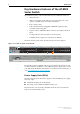
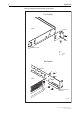
Release Note Figure 2: Fitting rack-mount brackets on the switch Front Bracket Switch Bracket A A A Rear bracket Key: A B screw nut Rear Bracket Bracket A A A Switch B B Adjustable bracket extension 8900RM AT-8900 Series Software Release 2.6.
Software Release 2.6.1 7 Packet Classifier The Generic Packet Classifier, or Classifier, performs packet classification. The Classifier defines packet matching rules that classify packets into data flows. A data flow is a categorisation of packets that obey a predefined rule and are processed in a similar manner. After you have defined the packet matching rules in the Classifier, other software features are used to specify what action is taken on a packet that matches the rule.
Release Note Configure Classifiers To create a classifier, use the command: CREATE CLASSIFIER=rule-id [MACDADDR={macadd|ANY}] [MACSADDR={macadd|ANY}] [MACTYPE={L2UCAST|L2MCAST| L2BCAST|ANY}] [VLAN={vlan-name|1..4094|ANY}] [ETHFORMAT={802.2-TAGGED|802.
Software Release 2.6.1 9 Table 2: Available ETHFORMAT and PROTOCOL parameter combinations ETHFORMAT= PROTOCOL= CLASSIFIER ASIC Chip SNAP [not specified] OK Error ANY OK Error IP OK OK Protocol=xxxxxx0800 IPX OK OK Protocol=xxxxxx8137 protocoltype OK OK [not specified] OK Error ANY OK Error IP Error n/a IPX OK (4) OK protocoltype OK OK 802.
Release Note Quality of Service (QoS) Quality of Service refers to the ability to intelligently manage network traffic to allow stable and predictable end-to-end network performance. QoS mechanisms enable: ■ the prioritisation of network traffic ■ the management of the bandwidth available to that traffic On the AT-8948 switch, QoS controls are applied to traffic ingressing ports.
Software Release 2.6.1 11 Table 3: Stages in the packet processing for QoS Stage Description For more information 1 The packet arrives at the ingress port. “Switch Ports”, Switching chapter, AT-8900 Series Software Reference. 2 For tagged packets, the switch maps the packet’s initial VLAN tag User Priority value to an egress queue. “How to Enable Layer 2 QoS Functionality on the switch” on page 32 For untagged packets, the switch assigns the packet to the default queue.
Release Note Figure 3: Packet flow through the QoS engine Packet Ingress Ingress port 1 Tagged: priority mapped to queue Untagged: mapped to default queue 2 Bridging processing 3 Classification 4 Premarking 5 Remarking 7 6 Metering Limiting (dropping non-conformant) IPv4 routing processing 8 Egress Queue shaping See Figure 4 on page 13 9 Queue emptying and egress 10 AT-8900 Series Software Release 2.6.
Software Release 2.6.
Release Note Destroying a QoS Element The components that make up a QoS solution are created as individual elements. Destroying a policy will not destroy any of the underlying entities. A logical link is created when a traffic class is added to a policy. Destroying the policy will only unlink the traffic class, leaving the traffic class in an unassigned state. Similarly, destroying traffic classes will simply unlink flow groups and destroying flow groups will simply unlink classifiers.
Software Release 2.6.
Release Note To assign traffic classes to a policy, use the command: ADD QOS POLICY=id TRAFFICCLASS=tcid-list To delete a traffic class from a policy, use the command: DELETE QOS POLICY=id TRAFFICCLASS={tcid-list|ALL} To display configuration information for one or more traffic classes, use the command: SHOW QOS TRAFFICCLASS[={id|ALL}] Default Traffic Class The default traffic class provides a catch-all for any traffic that does not match one of the traffic classes you assign to a policy.
Software Release 2.6.1 17 To assign a policy to a port or ports, use the command: SET QOS PORT={port-list|ALL} [POLICY={id|NONE}] [DEFAULTQUEUE=queue-number] [FORCEDEFQUEUE={YES|NO}] [RED={red-id|NONE}] Note that error checking of parameters and parameter values for the policy is only performed when the policy is set on a port.
Release Note Apply premarking to a flow group or traffic class To specify premarking, use the commands: CREATE QOS FLOWGROUP=flowgroup-list [MARKVALUE={dscp-value|NONE}] PREMARKING={USEMARKVALUE|USEDSCP|NONE} [other-parameters] SET QOS FLOWGROUP=flowgroup-list [MARKVALUE={dscp-value|NONE}] PREMARKING={USEMARKVALUE|USEDSCP|NONE} [other-parameters] CREATE QOS TRAFFICCLASS=id-list [MARKVALUE={dscp-value|NONE}] PREMARKING={USEMARKVALUE|USEDSCP|NONE} [other-parameters] SET QOS TRAFFICCLASS=id-list [MARKVALU
Software Release 2.6.1 19 Bandwidth Metering Metering allows you to select and specify the limits of the bandwidth allocation meter that measures the bandwidth used by a traffic class. You can select either a single-rate bandwidth allocation meter, or twin-rate bandwidth allocation meter. A twin-rate bandwidth allocation meter gives you greater sophistication in the management of traffic flows than a single-rate bandwidth allocation meter provides.
Release Note A single-rate bandwidth allocation meter A single-rate bandwidth allocation meter has one bandwidth threshold and two burstsize levels. See Table 5. Table 5: Properties of a single-rate bandwidth allocation meter Bandwidth class marker Service level Bandwidth class 1 Under maximum rate and under minimum burstsize. Bandwidth class 2 Bursting between minimum and maximum burstsize. Bandwidth class 3 Over maximum rate and over maximum burstsize.
Software Release 2.6.1 21 A twin-rate bandwidth allocation meter A twin-rate bandwidth allocation meter has a minimum bandwidth threshold and a maximum bandwidth threshold, and one level of burst per minimum and maximum threshold. See Table 6. Table 6: Properties of a twin-rate bandwidth allocation meter Bandwidth class marker Service level Bandwidth class 1 Under minimum rate and under minimum burstsize. Bandwidth class 2 Over minimum rate and burstsize and under maximum rate and burstsize.
Release Note To create and modify the twin-rate bandwidth metering properties for the default traffic class, use the commands: CREATE QOS POLICY=id-list [DTCDROPBWCLASS3={YES|NO}] DTCMAXBANDWIDTH={bandwidth|NONE} DTCMAXBURSTSIZE=burstsize DTCMINBANDWIDTH={bandwidth|NONE} DTCMINBURSTSIZE=burstsize [other-parameters] SET QOS POLICY=id-list [DTCDROPBWCLASS3={YES|NO}] DTCMAXBANDWIDTH={bandwidth|NONE} DTCMAXBURSTSIZE=burstsize DTCMINBANDWIDTH={bandwidth|NONE} DTCMINBURSTSIZE=burstsize [other-parameters] Re
Software Release 2.6.1 23 Set the properties of the DSCPMAP table As described above, one of the options for remarking is the DSCP mapping table. For each temporary bandwidth class and DSCP value, the table contains new values which the switch will assign for: ■ bandwidth class ■ DSCP ■ Egress Queue ■ VLAN Tag User Priority Using the DSCP mapping table allows you to specify the per-hop remarking actions for each frame according to the frame’s previous DSCP and bandwidth class.
Release Note Table 8: Initial values in the DSCPMAP table BWCLASS Class 1 Class 2 Class 3 NEWBWCLASS=1 NEWBWCLASS=2 NEWBWCLASS=3 NEWDSCP=0 NEWDSCP=0 NEWDSCP=0 NEWPRIORITY=0 NEWPRIORITY=0 NEWPRIORITY=0 NEWQUEUE=0 NEWQUEUE=0 NEWQUEUE=0 NEWBWCLASS=1 NEWBWCLASS=2 NEWBWCLASS=3 NEWDSCP=1 NEWDSCP=1 NEWDSCP=1 NEWPRIORITY=0 NEWPRIORITY=0 NEWPRIORITY=0 NEWQUEUE=0 NEWQUEUE=0 NEWQUEUE=0 DSCP 0 1 Set the properties of the QUEUE2PRIOMAP table As described in “Specifying remarking proper
Software Release 2.6.1 25 The parameters used in defining a RED curve are: ■ START The average length of the queue in bytes below which packets are always accepted. ■ STOP The average length of the queue in bytes above which packets are always discarded. ■ DROP Drop probability at the queue length determined by the STOP value. The queue length for RED Probability calculations is measured in numbers of bytes.
Release Note To destroy a single RED Curve set, or all RED Curve sets, use the command: DESTROY QOS RED={red-idlist|ALL} To implement RED curve functionality you need to configure a port on the switch. You can configure each egress port to use any of the four global RED Curve sets.
Software Release 2.6.1 27 The USEDSCPMAP option specifies that the temporary value of bandwidth conformance class is used (in conjunction with the DSCP of the frame) as an index into the DSCPMAP mapping table, which then assigns the actual, new values for bandwidth class, DSCP, Egress Queue and VLAN Tag User Priority.
Release Note To set the VLAN Tag Priority field assigned at egress for frames that were untagged at ingress, use the command: SET QOS DEFAULTPRIORITY=q0,q1,q2,q3,q4,q5,q6,q7 The integers p0 to p7 represent the VLAN Tag User Priority corresponding to an to an internal Class of Service queue. All eight values are required.
Software Release 2.6.1 29 To use the QoS tool set to configure a DiffServ domain: 1. Classify the packets coming into the domain at edge switches, according to the required characteristics. For available options, see the CREATE CLASSIFIER command in the Generic Packet Classifier chapter, AT-8900 Series Software Reference. Assign the classifiers to flow groups and the flow groups to traffic classes, with a different traffic class for each DiffServ code point grouping within the DiffServ domain.
Release Note How to Enable DiffServ QoS Functionality on the switch The switch will process traffic for Quality Of Service according to the guidelines provided by RFC2475 (An Architecture for Differentiated Services). DSCP-based classification, marking and meter-based remarking are supported. To enable DiffServ QoS functionality on the switch follow these steps: 1.
Software Release 2.6.1 31 5. Set the egress queue parameters for a port To update the parameters for all or specific egress queues on a port, use the command: SET QOS PORT={port-list|ALL} EGRESSQUEUE=queue-list [other-parameters] This command is used to rate limit and/or force congestion control of normally uncontested traffic. 6.
Release Note Layer 2 Priority-based QoS The switch will support Quality Of Service based on Layer 2 parameters for non-DiffServ compatible traffic. The selection of an egress queue based on the Layer 2 VLAN Tag Priority Field is supported for frames that are tagged at ingress, or by selecting a default queue per port for untagged frames. Meter remarking of Layer 2 priority on the basis of the selected egress queue and metering bandwidth conformance class is supported.
Software Release 2.6.1 33 2. Set the initial queue assignment for tagged frames To set the mapping of incoming VLAN Tag User Priorities to the internal service queues for ingressing packets that include a VLAN tag header, use the command: SET QOS PRIO2QUEUEMAP=p0,p1,p2,p3,p4,p5,p6,p7 The integers p0 to p7 indicate the queue priority corresponding to an incoming VLAN Tag User Priority. All eight values are required.
Release Note SET QOS QUEUE2PRIOMAP command The command syntax for the SET QOS QUEUE2PRIOMAP command in the AT-8900 Series Software Reference is incorrect. The correct command syntax is: SET QOS QUEUE2PRIOMAP QUEUE=queue-list BWCLASS=bwclasslist [NEWPRIORITY=vlan-priority] where: ■ bwclasslist is either an integer in the range 1 to 3; a range of integers (specified as 1-3) or a comma separated list of integers and/or ranges, without spaces.
Software Release 2.6.1 35 Auto MDI/MDI-X MDI and MDI-X are Medium Dependent Interface port configurations for copper based interfaces. An MDI interface at one end and an MDI-X (MDI crossover) interface at the other end of a straight-through cable ensures the correct correspondence between the transmitting and receiving interface cable pairs. If both ends have MDI interfaces, or both ends have MDI-X interfaces, a crossover cable is required. “Polarity” refers to whether a port operates as MDI or MDI-X.
Release Note Broadcast Storm Protection The storm control feature allows you to set limits on the reception rate of: ■ broadcast and multicast packets on a per port basis, i.e one limit per port ■ destination lookup packets for all ports on the switch, i.e one limit for the switch The switch hardware counts separately the number of broadcast, multicast, and destination lookup failure packets in bytes received per second, and discards packets once the byte limit is reached.
Software Release 2.6.1 37 Destination lookup failure packets Destination lookup failure packets have a Layer 2 destination address that the switch has not learnt and are in effect multicast packets. The switch does not know where to forward the packets, so the packets are broadcast to all ports on the switch. You can limit the rate at which destination lookup failure packets are received.
Release Note Creating VLANs To briefly summarise the process of creating a VLAN: 1. Create the VLAN and specify its classification, one of IP subnet, protocol, or port. 2. Add tagged ports to the VLAN, if required. 3. Create associations to associate subnets and protocols with the VLAN if untagged ports are required. These associations determine the VLAN that incoming untagged packets belong to. 4. Add untagged ports to the associations.
Software Release 2.6.1 39 Table 10: Types of VLAN available with each VLAN classification. VLAN classification Types of VLAN available with this classification IP subnet-based IP Subnet Protocol Port Protocol-based Protocol Port Port-based Port Protected VLANs The Protected VLAN feature prevents the members of a specified group of ports from communicating with each other, yet still allows these members to access another network.
Release Note To delete ports from a Protected VLAN, use the command: DELETE VLAN={vlan-name|1..4094} PORT={port-list|ALL} [GROUP=group-number|uplink-number] To disable Protected VLAN functionality on the switch, use the command: DISABLE VLAN PORTPROTECTED Multiple Spanning Trees and STP Interaction with VLANs If creating multiple STPs in a network, a port in a switch can belong to multiple STPs if the port is a member of more than one VLAN The AT-8900 Series Software Reference for Software Release 2.
Software Release 2.6.1 41 The Ingress and Egress Rules for Layer 2 Switching Two components of the Layer 2 switching process are the Ingress and Egress Rules. The Ingress Rules admit or discard frames based on their VLAN tagging. The Egress Rules determine for each frame whether VLAN tags are included in the Ethernet frames that are transmitted. The Ingress Rules All frames, tagged and untagged, received by a VLAN-aware switch must be associated with a VLAN.
Release Note Classifier-Based Packet Filters You can configure the switch hardware through entries in the Generic Packet Classifier, or Classifier, to copy, drop, forward, and associate QOS attributes to packets that match specified criteria. Every packet passing through the switch is matched against a series of classification tables by the Classifier.
Software Release 2.6.1 43 Addresses can be manually added to a port locked list up to a total of 256 MAC addresses, and the learning limit can be extended to accommodate them, by using the command: ADD SWITCH FILTER ACTION={FORWARD|DISCARD} DESTADDRESS=macadd PORT=port [ENTRY=entry] [LEARN] [VLAN={vlan-name|1..
Release Note SHOW IP INTERFACE For more information, see the Internet Protocol (IP) chapter of the AT-8900 Series Software Reference for Software Release 2.6.1. Dynamic Host Control Protocol for IPv6 The Dynamic Host Configuration Protocol for IPv6 (DHCP6) is used to delegate IPv6 prefixes, and to allocate IPv6 addresses. It offers stateful address autoconfiguration, and complements the stateless address autoconfiguration described in RFC 2462 “IPv6 Stateless Address Autoconfiguration”.
Software Release 2.6.1 45 4. Configure the server to delegate a prefix or range of prefixes by assigning the IPv6 prefixes to the policy and specifying a type of PD, using the command: CREATE DHCP6 RANGE=range POLICY=policy IP=ipv6address/prefix-ipv6address/prefix TYPE=PD Configure the server to delegate a range of addresses, by assigning a range of IPv6 addresses to the policy, using the command: CREATE DHCP6 RANGE=range POLICY=policy IP=ipv6address/prefix[-ipv6address/prefix] [TYPE={NORMAL|TEMP}] 5.
Release Note For background information, examples, more information about these commands, and information about other optional settings for DHCP6, see the Dynamic Host Configuration Protocol for IPv6 (DHCP6) chapter of the AT-8900 Series Software Reference for Software Release 2.6.1. For general information about configuring IPv6 interfaces, see the Internet Protocol version 6 chapter of the AT-8900 Series Software Reference for Software Release 2.6.1.
Software Release 2.6.1 47 Adding an IPv6 Host with a Link-Local IP Address Software Release 2.6.1 enables you to specify a host name to telnet to an IPv6 link-local address. It does this by allowing you to specify the interface as well as the address. Telneting to a link-local address requires interface information as well as the address, because a single link-local address can belong to several interfaces.
Release Note DHCP Compliance with RFC 2131 DHCP policies are no longer limited to a minimum lease time of 3600 seconds. This complies with RFC 2131, “Dynamic Host Configuration Protocol”. To create a DHCP policy, use the command: CREATE DHCP POLICY=name LEASETIME={lease-time|INFINITY} [INHERIT=name] where lease-time is a time in seconds. Routers or switches that comply with RFC 1541 but not with RFC 2131 may not be able to accept a lease time of less than 3600 seconds.
Software Release 2.6.1 49 User Authentication The following sections summarise extensions to the switch’s functionality for authenticating users via authentication servers. For more information about user privileges, authentication, and the commands outlined in these sections, see the Operation chapter of the AT-8900 Series Software Reference for Software Release 2.6.1.
Release Note To enable TACACS+, use the command: ENABLE TACPLUS To add a TACACS+ server, use the command: ADD TACPLUS SERVER=ipaddress [KEY=key] [PORT=port] [SINGLECONNECTION=YES|NO] [TIMEOUT=1...10] To enable TACACS+ debugging, use the command: ENABLE TACPLUS DEBUG Authorisation Services Authorisation occurs after authentication. It is here that an attribute value (AV) pair is returned if configured. Attribute Value Pairs are configured on the TACACS+ server and passed onto the switch.
Software Release 2.6.1 51 To calculate and display (Figure 9) one-time passwords, use the SEQUENCE and SEED parameters in the command: SHOW SKEY [SEQUENCE=seq_no SEED=seed_name [NUMBER=value]] where: ■ seq_no is an integer in the range 1-9999, representing the sequence number of the last S/Key or OTP password to be generated. ■ seed_name is the 1-16 alphanumeric user-defined string which was used to initialise the one-time password system on the authentication server.
Release Note Figure 10: Using a Radius Server for User Authentication. User dials into Access Server using Secure Shell (SSH) RADIUS requests packet encrypted with secret key RADIUS accepts including user privilege, or rejects Edge devices/ Access Servers Remote Users RADIUS Server RADIUS2 RADIUS and TACACS Debugging This enhancement supports debugging for the RADIUS and TACACS access control protocols. Access control packet debugging allows the contents of the packets to be viewed.
Software Release 2.6.1 53 Ping Polling of Device Reachability This enhancement enables the switch to regularly check whether or not it can reach a device. It also enables a trigger to activate on the switch when the device becomes unreachable. While the device is unreachable, the switch continues to monitor the device’s reachability, and another trigger can be set to activate when the device becomes available again.
Release Note switch to consider the device reachable again. The default is 30. The interaction between these parameters is shown in Figure 11. Figure 11: The interaction between states and parameters for ping polling. UP: device reachable after UPCOUNT consecutive ping replies after FAILCOUNT failed pings in SAMPLESIZE window LINKUP trigger activated LINKDOWN trigger activated DOWN: device unreachable Substates of UP: Up: No failed pings in SAMPLESIZE window. Poll frequency of NORMALINTERVAL.
Software Release 2.6.1 55 Ping Trigger The Trigger Facility can be used to automatically run specified command scripts when particular triggers are activated. When a trigger is activated by an event, parameters specific to the event are passed to the script that is run. For a full description of the Trigger Facility, see the Trigger Facility chapter of the AT8900 Series Software Reference for Software Release 2.6.1.
Release Note Parameters Script Arguments Example The following command parameter can be specified in the CREATE/SET TRIGGER commands. Parameter Description POLL=poll-id The ID number of the ping poll that this trigger relates to. The trigger passes the following argument to the script: Argument Description %1 The ID number of the ping poll that this trigger relates to.
Software Release 2.6.1 57 SNMP Community Names - Support for all Printable ASC11 Characters SNMP community names now support the inclusion of any printable ASCII character.