
Specifications
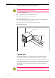

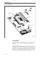
Table Of Contents
- AT-8900 Series Hardware Reference
- Contents
- Models Covered By This Reference
- Why You Should Read This Reference
- Where To Find More Information
- Hardware Description
- Online Documentation
- AT-TFTP Server
- Using Windows Terminal and Windows Hyperterminal
- Switch Start-up
- RS-232 Terminal Port (ASYN0)
- Useful Cables
- Test Facility
- Power Supply Units (PSUs)
- Port, Connector, and Cable Combinations
- Troubleshooting
- Expansion Options
- Restricted Procedures
- Contacting Us

Hardware Reference 33
C613-03075-00 REV A
For AT-8900 Series switches, DIMM should only be installed by authorised
service personnel. Unauthorised opening of the switch’s lid may cause danger
of injury from electric shock, damage to the switch, and invalidation of the
product warranty.
To install DIMM in an AT-8900 series switch:
1. Avoid injury by working in a safe environment.
The workspace should be free of hazards, and there should be sufficient
room to lay out the switch, DIMM, and tools.
2. Disconnect the mains power cord.
Before removing the switch’s lid the power cord(s) to the PSU(s) should be
disconnected to reduce risk of electrical shock.
3. Remove all interface cables.
4. Remove the switch’s lid.
The switch may need to be removed from any rack mounting system
before its lid can be removed.
Using a posidrive screwdriver, remove the 7 screws that secure the switch’s
lid. There are 3 screws located in countersunk holes on each side of the lid,
and 1 screw at the top.
5. Prepare the DIMMs.
In an antistatic environment, remove the DIMM from its packing material.
Be sure to observe ESD precautions.
Do not attempt to install DIMM without observing correct antistatic
procedures. Failure to do so may damage the DIMM and switch. If you are
unsure what the correct procedures are, contact your authorised Allied Telesyn
distributor or reseller.
6. To remove an existing DIMM.
Before removing the switch’s lid the power cord(s) to the PSU(s) should be
disconnected to reduce risk of electrical shock.
The DIMM is held in place by two retaining latches, one latch at each end
of the DIMM slot. Release these latches and carefully pull the DIMM from
the DIMM slot.
The DIMM slot’s location is shown in Figure 13 on page 34.