AlliedView™-EMS 3.8 (Full Installation) DEVICE MANAGEMENT GUIDE AlliedView™-EMS 3.
TABLE OF CONTENTS BASIC OPERATIONS........................................................................................................................................................... 9 COMMON OPERATIONS ON THE MAIN WINDOW ................................................................................................................ 9 MENU FOR STACKED DEVICES ...............................................................................................................................................
EXPANSION MODULE NOTES ...............................................................................................................................................70 AT-8324SX ...........................................................................................................................................................................72 MAIN WINDOW ...................................................................................................................................................
AGENT MENU ......................................................................................................................................................................112 ROUTING MENU ..................................................................................................................................................................113 BRIDGE MENU ............................................................................................................................................
ROUTING MENU ..................................................................................................................................................................156 BRIDGE MENU ......................................................................................................................................................................157 RMON MENU .............................................................................................................................................
ROUTING MENU ..................................................................................................................................................................204 BRIDGE MENU ......................................................................................................................................................................204 PORT MENU .............................................................................................................................................
AT-MCF106 FAMILY ........................................................................................................................................................266 MAIN WINDOW ..................................................................................................................................................................266 AGENT MENU ......................................................................................................................................................
MAIN WINDOW ..................................................................................................................................................................313 AGENT MENU ......................................................................................................................................................................314 ROUTING MENU ............................................................................................................................................
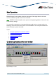
Basic Operations Device Manager's main window shows the main panel of the target device. It has both common and device-specific menus on its menu bar. Note - SNMPv3: All device-specific menu options are displayed regardless of the user's view access security settings. You can perform operations on the agent by doing a right click on the main panel or by selecting a menu item from the menu bar. Ports and LEDs on the main panel indicate the status of the port, system and traffic.
Port Right clicking on a port opens a pull-down menu specific to the device. Selecting a menu item opens another window and lets you view and edit MIB information related to the port. You can also access the same menu from the menu bar. RS-232 Terminal Port Right clicking on an RS-232 port opens a pull-down menu and lets you choose how to log into the agent. Depending on the managed device, choose Telnet or WEB Browser.
Module submenu Port selection dialog box When you select a menu item acting on ports, a dialog box opens to let you select ports. Check the target ports and click OK. Note - If you select multiple ports, it may take some time for data to be displayed. AlliedView™-EMS 3.
Select Port dialog box Port status colors Port status is shown by its color. Port speed is also displayed in the port image. • Link Up: Green • Disabled: Red (the port is disabled by an administrator) • Partitioned/Blocking: Yellow • Others: Default colour (usually black) Note - SNMPv3: Depending on the READ VIEW access settings of the User Account Name used, there is a possibility that Device Manager may not be able to access some MIB values that control the Port status.
AT-8000 Series This section describes Device Manager menus and operations specific to the AT-8000 Series. Topics: • • • • • • • Main Window Agent Menu Bridge Menu RMON Menu Port Menu Stacking Menu Expansion Module Notes Main Window AT-8012M AlliedView™-EMS 3.
AT-8012M-QS AT-8016F/MT AlliedView™-EMS 3.
AT-8016F/SC AT-8016F/ST AlliedView™-EMS 3.
AT-8024 AT-8024GB AlliedView™-EMS 3.
AT-8024M AT-8026FC AlliedView™-EMS 3.
AT-8026T AT-8088/MT AlliedView™-EMS 3.
AT-8088/SC Device Manager LEDs for AT-8000 Series LED State Description PWR Green The switch is receiving power. MASTER Orange Gray DUPLEX Green Orange The switch is the master switch of an enhanced stack. The switch is a slave switch or is not a member of an enhanced stack. The port is operating in full-duplex mode. The port is operating in half-duplex mode. Note - Please refer to Uplink Modules for the operations and behavior of the expansion modules installed on these devices.
Note - Connection between an AT-8024GB and an AT-8324 can only be established if the uplink ports on both devices are configured to auto-negotiate. Note - Setting the 'Active Protocol Version' to 'STP' and 'Spanning Tree Status' to 'enabled' will set the Port State parameter of disabled ports to 'blocking'. As a result, port images for disabled ports will turn yellow.
MAC Address Table Displays a list of static MAC addresses configured on the switch. Note - MAC Address Table entries created through a local or telnet management session will not be visible to Device Manager until the device is restarted. Reset Telnet Resets the switch. Starts a Telnet connection to the switch. WEB Browser Connects to the switch's HTTP server. Bridge Menu From the Bridge menu, you can view and edit bridge information such as the forwarding database and the spanning tree status.
Statistics Displays traffic statistics in the network segment attached to each port. History Control Table Displays the RMON History table. Note - The current firmware version does not support the "historyControlTable" MIB object of RFC1757. As a result, Device Manager displays the error message "Failed to get MIB data." when the History Control Table option is selected from the RMON menu. Alarm Table Displays the RMON Alarm table. Event Table Displays the RMON Event table.
• • • • Expansion module ports GBIC ports on the AT-8024GB Fiber optic ports on the AT-8026FC 10/100/1000Base-T ports on the AT-8026T Note - Valid MIB Set values for the Port State parameter are 'enabled' and 'disabled'. Attempting to set this parameter to any other value will result in the error message: "The error occurred with 'Set' operation. Error: bad value." Note - The current firmware version accepts up to 20 characters for the Port Name parameter.
new value to be converted to its equivalent wrap-around value; i.e., 65536 will become 0, 65537 will become 1, and so on. Note - The current firmware version does not allow the Port Mirroring Status parameter to be set to 'receive' and 'transmit'. Attempting to do so will result in the error message: "The error occurred with 'Set' operation. Error: bad value". Note - By default, the Port Mirroring Status parameter is set to 'disabled' and the Mirroring Destination Port parameter is set to 0.
• The Spanning Tree Protocol (STP) does not work for the AT-A46 expansion module when it is installed on an AT-8016F/ST device. As a result, the Port State parameter of the AT-A46 expansion module port will never be set to 'blocking' and the port image will never turn yellow. • Connection between an AT-A47 expansion module port that is configured to operate at 1Gbps full duplex and a port on another device can only be established if the port on the other device is configured to auto-negotiate.
AT-8000S Series This section describes Device Manager menus and operations specific to the AT-8000S Series. Topics: • • • • • • • • Main Window Agent Menu Routing Menu Bridge Menu IGMP Menu Security Menu RMON Menu Port Menu Main Window AT-8000S/16 AlliedView™-EMS 3.
AT-8000S/24, AT-8000S/48 and POE Models The AT-8000S/24, AT-8000S24/POE, AT 8000S/48 and AT-800S/48 POE can be joined together into a stack of up to 6 units. AlliedView™-EMS 3.
Device Manager LEDs for AT-8000S Series LED State Description PWR Green The switch is receiving power. STACK ID Orange DUPLEX The stacked unit is either the Stacking Master or the Backup Master. Gray The switch is a set to standalone mode. Green The stacked unit is a slave switch. Green The port is operating in full-duplex mode. Orange The port is operating in half-duplex mode.
Device Info General Info Displays common management information. Active Software File Displays the currently available images on the flash. Physical Description Basic Info Displays the number of stack units. Module Info Displays module information for each unit in the system. Port Attributes Displays port information. Stack Info Displays information about the stacked devices. Stack Active Unit ID Displays the current unit ID of the device after reset.
Software Packages Displays the device's software packages. Management Info General Management Displays common management information. Flash File System Basic Info Displays the flash file size of the device. File List Displays the device's list of files. Note - The current firmware version does not allow the Row Status parameter to be configured. Jumbo Frames Displays the current jumbo frames status. Management ACL Basic Info Displays basic information about the management access list.
General Tuning Displays general tuning information. Note - The current firmware version accepts values in the range [0-255] inclusive for the Debug Level parameter. Max Entries Tuning Displays information about the maximum entries in tuning.
Terminal Debug Mode Displays the terminal debug mode password. Note - The current firmware version does not allow the Terminal Debug Mode Password to be configured. Telnet Basic Info Displays the basic telnet information. Telnet Sessions Displays the login time, client ip address and telnet session status. CLI Info Displays information if the file is enabled or not. LCLI Info Displays information about the device's Telnet sessions and SSH sessions if enabled or not.
SNTP/NTP Client Config Displays information about SNTP/NTP client configuration. Note - Valid MIB Set values for the Polling Interval parameter should range from 60 to 86400. However, the current firmware version allows the user to enter values in the range [-2147483648 to 2147483647] inclusive. Attempting to enter values greater than 2147483647 will cause the new value to be converted to its equivalent wrap-around value; i.e.
Syslog Collector Displays the information to generate syslog messages to an aggregating agent or collector. Syslog Application Displays information about a managed entity that provides individual control over the severity level of the messages that it will generate. Note - The current firmware version does not allow the Severity parameter to be configured. Reset Telnet Resets the switch. Starts a Telnet connection to the switch. WEB Browser Connects to the switch's HTTP server.
Note - The current firmware version does not allow the Routing Type parameter to be set to ‘local’ for all models except the AT-8000S/16. For the AT-8000S/16, the Routing Type parameter cannot be set to ‘remote.’ IP Statistics Displays statistics about IP routing, including the number of IP datagrams received. Note - The current firmware version does not allow the Forwarding Status parameter to be configured. ARP Table Config Displays configuration information about ARP.
Route Table Displays the CIDR routing tables. Note - The current firmware version does not allow the following parameters to be configured: o Destination Port Number o Routing Protocol MIB o Destination Metric 2 o Destination Metric 3 o Destination Metric 4 o Destination Metric 5 Note - The current firmware version does not allow the Routing Type parameter to be set to ‘local’ for all models except the AT-8000S/16. For the AT-8000S/16, the Routing Type parameter cannot be set to ‘remote.
Negative Cache Info Displays information about a collection of objects providing access to and control of a DNS resolver's negative response cache. Additional Counters Displays information about a collection of objects providing further instrumentation applicable to many but not all DNS resolvers. Bridge Menu From the Bridge menu, you can view and edit bridge information such as the forwarding database and the spanning tree status. Forwarding Database Displays the Forwarding Database table.
Note - The current firmware version does not allow the Number of Traffic Class parameter to be configured. 802.1p Device Capabilities Displays information on the device capabilities. Port Priority Group Displays information about the port priority. Traffic Class Displays information about the traffic class and traffic class priority. Note - Valid MIB Set values for the Traffic Class parameter are in the range [0-3] inclusive.
Note - The current firmware version does not allow the EAP Current Method List parameter to be configured. Method Lists Displays information about all method lists. Note - The current firmware version does not allow the Row Status parameter to be configured. Lines Displays information about all lines, their passwords and their authorization levels. Note - The current firmware version does not allow the Password, Row Status and Password Valid Time parameters to be configured.
Note - The current firmware version returns a 'noSuchName' value for the Port Number parameter. Note - The current firmware version does not allow the Administrative Controlled Directions and Key Transmission Status parameters to be configured. Authenticator PAE Statistics Displays statistics objects for the Authenticator PAE associated with each port. Note - The current firmware version returns a 'noSuchName' value for the Port Number parameter.
Note - The current firmware version is unable to display any value for the Client ID parameter. Authentication Server Info Displays the list of RADIUS authentication servers with which the client shares a secret. Accounting Client Info Displays the number of RADIUS Access-Response packets received from unknown addresses and the identifier of the RADIUS accounting client. Note - The current firmware version is unable to display any value for the Client ID parameter.
Secure Socket Layer Basic Info Displays basic SSL information. Note - The current firmware version does not allow the Certificate Save parameter to be configured. Certificate Generation Displays information about the generated keys and self signed certificates. Note - The current firmware version does not allow any of the parameteres under this table to be configured. Export Certificate Displays information about the saved data from RAM and flash.
Note - The current firmware version does not allow Device Manager to display Utilization information. Interface Info Standard Displays port statistics such as the number of frames received and transmitted on the port, bytes received and transmitted on the port, and port status. Note - The current firmware version does not allow the Promiscuous Mode parameter to be configured.
Note - The current firmware version is unable to display any value for the Port Number and Alignment Error Frames (HC) parameters. Note - The current firmware version returns a ‘noSuchName’ value for the Internal MAC Transmit Errors (HC) and Internal MAC Received Errors (HC) parameters. Detail Info Displays detailed port information such as duplex mode.
Enable Disable Enables the port. Disables the port. Port Lock Basic Info Displays basic information about port lock. Interfaces Range Displays information about port lock interfaces range. MAC Control MAC Control Sublayer Displays information about the MAC Control sublayer on a single ethernet-like interface. Note - The current firmware version returns a 'noSuchName' value for the Unknown Opcodes Received and Unknown Opcodes Received (HC) parameters.
Tail Drop/WRED Displays information about the Tail Drop or WRED parameters and the EF of WRR parameters. Note - The current firmware version does not allow the Row Status parameter to be configured. DSCP Mutation Displays information about the new DSCP for the packet. DSCP Remark Displays information about the DSCP remark packet. Note - The current firmware version does not allow the New DSCP parameter to be configured. QoS to Queue Displays information about the queue ID.
Default VPT to Queue Displays information about the VLAN tag priority. Default DSCP to Queue Displays information about the setting of default dscp to queue map. Queue Profiles Displays information about the queue management profiles. Note - The current firmware version does not allow the Queue Value parameters to be configured. Port Trunking Basic Info Displays basic information about port trunking. Note - The current firmware version does not allow any of the parameters under this table to be configured.
Status and Partner Operational Status parameters will also display unrecognizable values. Note - The current firmware version does not allow the Actor Administrative Key and Partner Administrative System ID parameters to be configured. Storm Control Basic Info Displays basic information about storm control. Storm Control Protection Displays information about the storm control protection per port. Note - Only the Broadcast Enable and Multicast Enable parameters can be configured.
AT-8124 This section describes Device Manager menus and operations specific to the AT-8124 switch. Topics: • • • • • Main Window Agent Menu Bridge Menu RMON Menu Port Menu Main Window AT-8124 Device Manager LEDs for AT-8124 LED State Description PWR Green The switch is receiving power. DUPLEX Green Gray The port is operating in full-duplex mode. The port is operating in half-duplex mode. AlliedView™-EMS 3.
Agent Menu From the Agent menu, you can view and edit the system information for the device or log into the CLI using telnet. System Info Displays basic system information, including system name, location, contact and description. Network Info Displays network-related information such as the device's IP address, and the default gateway address. Firmware Info Displays the version of the software running on the managed device. Manager Address Info Displays the management station's IP address.
Statistics Displays statistics about frames received/transmitted on the switch port. RMON Menu From the RMON menu you can view and edit the RMON MIB. Note - Since there may be a large quantity of RMON data, it may take some time for the information to appear. Statistics Displays traffic statistics about the network segment attached to each port. History Control Table Displays the RMON History table. Alarm Table Displays the RMON Alarm table. Event Table Displays the RMON Event table.
Detail Status Displays detailed port information such as duplex mode. Spanning Tree Info Displays the port's spanning tree parameters. Enable Disable Enables the port. Disables the port. AT-8124 AlliedView™-EMS 3.
AT-8124XL (V2) This section describes Device Manager menus and operations specific to the AT-8124XL (V2) switch. Topics: • • • • • Main Window Agent Menu Bridge Menu RMON Menu Port Menu Main Window AT-8124XL (V2) Device Manager LEDs for AT-8124XL (V2) LED State Description PWR Green The switch is receiving power. DUPLEX Green Orange The port is operating in full-duplex mode. The port is operating in half-duplex mode. AlliedView™-EMS 3.
Agent Menu From the Agent menu, you can view and edit the system information for the device, or log into the CLI using Telnet. System Info Displays basic system information, including system name, location, contact and description. Note - Device Manager allows the user to enter up to 255 characters for the System Contact, System Name, and System Location parameters but truncates them to 64 characters. NULL values are not accepted. Firmware Info Displays firmware version.
Discard/Aging Time Info Displays information about the number of address entries that were learned but discarded because either there was a lack of memory or the entry's aging timer expired. Spanning Tree Info Displays spanning tree parameters such as priority and cost. Statistics Displays statistics about frames received/transmitted on the switch's ports. RMON Menu From the RMON menu you can view and edit the RMON MIB. Statistics Displays traffic statistics in the network segment attached to each port.
Detail Info Displays detailed port information such as duplex mode. Note - Enabling/Disabling the Port STP Configuration parameter for one port enables/disables STP for all ports. Note - Attempting to modify the Port Speed and Mode parameter from 'auto sense' to '1Gbps half-duplex' or '1Gbps full-duplex' will result in the following: • An error message: "The error occurred with 'Set' operation.
Displays port mirroring parameters and allows configuration of port mirroring state, source, and destination. IGMP Snooping Displays the current state of IGMP Snooping and allows reconfiguration. AT-8124XL (V2) AlliedView™-EMS 3.
AT-8200XL Series This section describes Device Manager menus and operations specific to the AT8216FXL/SC and AT-8224XL switches. Topics: • • • • • • Main Window Agent Menu Bridge Menu RMON Menu Port Menu Expansion Module Notes Main Window AT-8216FXL/SC AlliedView™-EMS 3.
AT-8224XL Device Manager LEDs for AT-8200XL Series LED State Description PWR Green The switch is receiving power. RPS Green An optional redundant power supply is connected to the switch. Gray There is no redundant power supply connected to the switch. DUPLEX Green Orange The port is operating at full-duplex mode. The port is operating at half-duplex mode. Note - Please refer to Uplink Modules for the operations and behavior of the expansion modules installed on these devices.
Note - The current firmware version allows the user to enter up to 64 characters for the System Contact and the System Location parameters and up to 20 characters for the System Name parameter. Note - The current firmware version appends a period '.' and the value of the Default Domain Name parameter to the value of the System Name parameter. Firmware Info Displays the firmware version of the switch.
Diagnostics Displays the operating status of the switch's components such as power supply and system fans. Note - The current firmware version returns 'non-supported' for the following parameters: • Fan Speed 3 • 3.3V Power • 2.5Va Power • 2.5Vb Power • 2V Power • CPU Temperature Reset Resets the switch. Console Settings Displays the current settings of the console. Telnet Starts a Telnet connection to the switch. WEB Browser Connects to the switch's HTTP server.
Discard/Aging Time Info Displays information about the number of address entries that were learned but discarded because either there was a lack of memory or the entry's aging timer expired. Spanning Tree Info Displays spanning tree parameters such as priority and cost. Statistics Displays statistics about frames received/transmitted on the switch port. RMON Menu From the RMON menu you can view and edit the RMON MIB. Statistics Displays traffic statistics in the network segment attached to each port.
Error Statistics Displays error statistics. Detail Info Displays detailed port information such as duplex mode. Note - The Port Flow Control parameter has a fixed value of 'not supported' and cannot be modified. Note - When the Port Speed and Mode parameter of an AT-8224XL fixed port is set to 'auto sense' and the port is connected to a full duplex port on another device, its corresponding Duplex LED on the device image turns orange instead of green.
Expansion Module Notes • When the Port Speed and Mode parameter of an AT-A14 expansion module port is set to 'auto sense' and the port is connected to a 100Mbps full duplex port on another device, its corresponding Duplex LED on the device image turns orange instead of green. • The current firmware version does not allow the Port Speed and Mode parameter of the AT-A14 expansion module port to be set to any value other than 'auto-sense'.
AT-8324 This section describes Device Manager menus and operations specific to the AT-8324 switch. Topics: • • • • • • Main Window Agent Menu Bridge Menu RMON Menu Port Menu Expansion Module Notes AlliedView™-EMS 3.
Main Window AT-8324 Supports up to 8 stacked AT-8324 switches. LED State Device Manager LEDs for AT-8324 Description PWR Green The switch is receiving power. DUPLEX Green Orange The port is operating in full-duplex mode. The port is operating in half-duplex mode. Note - Please refer to Uplink Modules for the operations and behaviour of the expansion modules installed on this device. AlliedView™-EMS 3.
Note - The current firmware version does not allow Device Manager to support the RPS and MASTER LEDs. Note - When a port is configured to auto-negotiate, the current firmware version does not always update its Port Duplex Status parameter with the correct negotiated mode. As a result, the port's Duplex LED may show up as green when it should really be orange and vice-versa. Agent Menu From the Agent menu, you can view and edit the system information for the device, or log into the CLI using Telnet.
Bridge Menu From the Bridge menu, you can view and edit bridge information such as the forwarding database and the spanning tree status. Forwarding Database Displays the Forwarding Database table. Discard/Aging Time Info Displays information about the number of address entries that were learned but discarded because of lack memory or the entry's aging timer has expired. Note - The current firmware version accepts values in the range [8-512] inclusive for the Aging Time parameter.
Event Table Displays the RMON Event table. Event Log Displays the RMON Event log. Port Menu From the Port menu, you can view and edit MIB information about the port. Note - The current firmware version does not allow Device Manager to support the following features: • Spanning Tree Info • Class of Service • IGMP Snooping Utilization Displays the port's utilization information.
These parameters are defined in v2.13 but will return 'noSuchName.' because they do not exist in v1.0. Note - The current firmware version does not allow the Port State parameter to be set to 'enabled'. Attempting to do so will result in the error message: "The error occurred with 'Set' operation. Error: bad value." To enable a port, click on the Enable option under the Port menu. Note - 4 ports are allotted for each expansion module slot.
• The Port Speed and Mode parameter of the 1000Base-X port on the AT-A15 expansion module can only be set to '1Gbps full-duplex'. Attempting to set this to any other value will result in the error message: "The error occurred with 'Set' operation. Error: gen Error". • The Port Speed and Mode parameter of the 100Base-FX port on the AT-A16, ATA17, and AT-A19 expansion modules can only be set to '100Mbps full-duplex'.
AT-8324SX This section describes Device Manager menus and operations specific to the AT-8324SX switch. Topics: • • • • • • Main Window Agent Menu Bridge Menu RMON Menu Port Menu Stacking Menu AlliedView™-EMS 3.
Main Window AT-8324SX Supports up to 4 stacked switches. AlliedView™-EMS 3.
LED State Device Manager LEDs for AT-8324SX Description PWR Green The switch is receiving power. RPS Green Redundant power is ON. Gray Redundant power is OFF. Gray The port is operating in full-duplex mode. Orange The port is operating in half-duplex mode. Green The switch's position in the switch stack. DUPLEX STACK ID Note - When multiple units of AT-8324SX are stacked together, port numbering is continuous.
Telnet Starts a Telnet connection to the switch. WEB Browser Connects to the switch's HTTP server. Bridge Menu From the Bridge menu, you can view and edit bridge information, such as the forwarding database and spanning tree status. Forwarding Database Displays the Forwarding Database table. Discard/Aging Time Info Displays information about the number of address entries that were learned but discarded because either there was a lack of memory or the entry's aging timer expired.
Event Log Displays the RMON event log. Port Menu From the Port menu, you can view and edit MIB information about the port. Note - The current firmware version does not allow Port Menu to support the Class of Service. Utilization Displays the port's utilization information. Interface Info Displays port statistics such as the number of frames received and transmitted on the port, bytes received and transmitted on the port, and port status.
Spanning Tree Info Displays the port's spanning tree parameters. Enable Disable Enables the port. Disables the port. Port Mirroring Displays port mirroring parameters and allows configuration of port mirroring state, source, and destination. IGMP Snooping Displays the current state of IGMP Snooping and allows reconfiguration. Note - Valid MIB Set values for the IGMP Report Delay parameter should range from 5 to 30.
AT-8300GB Series This section describes Device Manager menus and operations specific to the AT-8300GB Series. Topics: • • • • • • Main Window Agent Menu Bridge Menu RMON Menu Port Menu Stacking Menu AlliedView™-EMS 3.
Main Window AT-8326GB The AT-8326GB supports up to 6 AT-8326GB stacked switches or any of the following mixed stack combinations of AT-8326GB and AT-8350GB switches: • Two AT-8326GB switches and one AT-8350GB switch • Two AT-8326GB switches and two AT-8350GB switches • Three AT-8326GB switches and one AT-8350GB switch • Four AT-8326GB switches and one AT-8350GB switch AlliedView™-EMS 3.
Note - When 3 or more AT-8326GB devices are stacked together, expect the twisted pair port image of Port 26 on the last device on the stack to turn green. This is because the current firmware version returns 'on-line' for the Port Link State parameter of the port even if there is no link established. AT-8350GB The AT-8350GB supports up to 3 stacked AT-8350GB switches. Note - The current firmware version does not allow Device Manager to support the RPS LED.
Note - The current firmware version does not allow Device Manager to detect the presence or absence of a GBIC module in any of the GBIC slots. As a result, the GBIC slots on the device image will remain empty regardless of whether or not GBIC modules are physically present in the slots. Agent Menu From the Agent menu, you can view and edit the system information for the device, or log into the CLI using Telnet.
Bridge Menu From the Bridge menu, you can view and edit bridge information such as the forwarding database and the spanning tree status. Forwarding Database Displays the Forwarding Database table. Discard/Aging Time Info Displays information about the number of address entries that were learned but discarded because of lack of memory or the entry's aging timer has expired. Note - The current firmware version accepts values in the range [10-1000000] inclusive for the Aging Time parameter.
Port Menu From the Port menu, you can view and edit MIB information about the port. Utilization Displays the port's utilization information. Interface Info Displays port statistics such as the number of frames received and transmitted on the port, bytes received and transmitted on the port, and port status. Note - Valid MIB Set values for the Administration Status parameter are 'up' and 'down'.
QoS Displays QoS parameters and allows enabling of QoS status and setting priority queue. Port Mirroring Displays port mirroring parameters and allows configuration of port mirroring state, source and destination. IGMP Snooping Displays the current state of IGMP Snooping and allows reconfiguration. Stacking Menu From the Stacking menu, you can view basic switch information as well as stacking information.
AT-8400 This section describes Device Manager menus and operations specific to the AT-8400 switch. Topics: • • • • • • Main Window Agent Menu Bridge Menu RMON Menu Port Menu Stacking Menu Main Window AT-8400 AlliedView™-EMS 3.
LED Device Manager LEDs for AT-8401 Management Module State Description FAN A Green FAN TRAY A is installed and is operating correctly. Gray FAN TRAY A is not installed. Green FAN TRAY B is installed and is operating correctly. Gray FAN TRAY B is not installed. Green The switch is the master of an enhanced stack. Gray The switch is either a slave switch of an enhanced stack or the switch is not a member of an enhanced stack.
Agent Menu From the Agent menu, you can view and edit the system information for the device, or log into the CLI using Telnet. System Info Displays basic system information, including system name, location, contact and description. Network Info Displays network-related information such as the addresses of the default gateway and the agents. Note - The current firmware version does not allow the DNS Server and Default Domain Name parameters to be configured.
Bridge Menu From the Bridge menu, you can view and edit bridge information such as the forwarding database and the spanning tree status. Forwarding Database Displays the Forwarding Database table. Note - It may take some time to retrieve Forwarding Database information. As a result, some Forwarding Database parameters may not show any value. To avoid this, click on File > Property > Polling options and set the Polling Interval parameter to 25 seconds or longer.
Note - The current firmware version does not support the "historyControlTable" MIB object of RFC1757. As a result, Device Manager displays the error message "Failed to get MIB data." when the History Control Table option is selected from the RMON menu. Alarm Table Displays the RMON Alarm table. Event Table Displays the RMON Event table. Event Log Displays the RMON Event log. Port Menu From the Port menu, you can view and edit MIB information about the port.
Spanning Tree Info Displays the port's spanning tree parameters. Note - The current firmware version does not allow the Port parameter to be configured. Attempting to configure this parameter will result in the error message: "The error occurred with 'Set' operation. Error: readOnly". Port Security Displays the port security attributes for each physical port present in the switch. Enable Disable Enables the port. Disables the port.
AT-8400 Line Cards This section describes the AT-8400 Line Cards supported by Device Manager. If line cards are installed on the AT-8400 chassis at the time Device Manager is called, they will be displayed in their corresponding slots on the chassis image. • • • • AT-8411 AT-8412 AT-8413 AT-8414 AT-8411 AT-8411 LED State Description DUPLEX Green The port is operating in full-duplex. Orange The port is operating in half-duplex.
AT-8412 AT-8412/MT AT-8412/SC LED State Description DUPLEX Green The port is operating in full-duplex. Note - The current firmware version does not allow the Port Flow Control parameter of ports on the AT-8412/MT and AT-8412/SC line cards to be set to 'auto'. Attempting to set this parameter to 'auto' will result in the error message: "The error occurred with 'Set' operation. Error: gen Error". AlliedView™-EMS 3.
AT-8413 AT-8413GB/T LED State Description DUPLEX Green The port is operating in full-duplex. Orange The port is operating in half-duplex. Note - A GBIC image is always visible on the GBIC slot of the AT-8413GB/T line card image even if there is no GBIC physically present in the slot. Note - Status information for the AT-8413GB/T ports will always be reflected on the RJ-45 port image regardless of whether the port that is in actual use is the GBIC port or the twisted pair port.
AT-8414 AT-8414/SC AT-8414/ST LED State Description DUPLEX Green The port is operating in full-duplex. Orange The port is operating in half-duplex. Note - The Port Negotiation parameter of ports on the AT-8414/SC and AT-8414/ST line cards has a fixed value of '10Mbps full-duplex' and cannot be modified. AT-8400 Line Cards AlliedView™-EMS 3.
AT-9006 Family This section describes Device Manager menus and operations specific to the AT-9006SX/SC and AT-9006T switches. Topics: • • • • • • Main Window Agent Menu Bridge Menu RMON Menu VLAN Menu Port Menu Main Window AT-9006SX/SC AlliedView™-EMS 3.
AT-9006T Device Manager LEDs for AT-9006 Family LED State Description PWR Green The switch is receiving power. RPS Green An optional redundant power supply is connected to the switch. Gray There is no redundant power supply connected to the switch. DUPLEX Green Orange The port is operating in full-duplex mode. The port is operating in half-duplex mode. Note - Ports on the expansion modules are numbered starting from 7.
Network Info Displays network-related information such as agent's and default gateway address. Manager Address Info Displays management station's IP address. Reset Telnet Reset the switch. Connect to the switch's telnet service. Bridge Menu From the Bridge menu, you can view and edit information such as forwarding database and spanning tree status. Forwarding Database Displays forwarding database table.
Event Table Displays RMON Event table. Event Log Displays RMON Event log. VLAN Menu From the VLAN menu, you can view the list of VLAN and member ports. Note - You cannot modify VLAN configuration on the AT-9006 Family using the VLAN menu. Name List Displays configured VLAN names. Port Info Displays VLAN to which the port belongs. Port Menu From the Port menu, you can view and edit MIB information about the port. Utilization Displays port's utilization information.
Disable Disables the port. AT-9006 Family AlliedView™-EMS 3.
AT-9410GB This section describes Device Manager menus and operations specific to the AT-9410GB switch. Topics: • • • • • Main Window Agent Menu Bridge Menu RMON Menu Port Menu Main Window AT-9410GB Device Manager LEDs for AT-9410GB Description LED State PWR Green The switch is receiving power. DUPLEX Green The port is operating at full-duplex mode. Orange The port is operating at half-duplex mode.
Note - When a port on the AT-9410GB is set to 'auto sense' and is connected to a halfduplex port on another device, its corresponding Duplex LED on the device image turns green instead of orange. Note - A GBIC image is always visible on each of the GBIC slots of the device image even if there are no GBICs physically inserted. Agent Menu From the Agent menu, you can view and edit the system information for the device, or log into the CLI using Telnet.
Reset Telnet Resets the switch. Starts a Telnet connection to the switch. WEB Browser Connects to the switch's HTTP server. Bridge Menu From the Bridge menu, you can view and edit bridge information such as the forwarding database and the spanning tree status. Bridge Info Displays basic bridge information such as the LAN ID, bridge address, number of ports and the bridge type. Forwarding Database Displays the Forwarding Database table.
Alarm Table Displays the RMON Alarm table. Event Table Displays the RMON Event table. Event Log Displays the RMON Event log. Port Menu From the Port menu, you can view and edit MIB information about the port. Utilization Displays the port's utilization information. Interface Info Displays port statistics such as the number of frames received and transmitted on the port, bytes received and transmitted on the port, and port status.
Note - Valid MIB Set values for the Port State parameter are 'enabled' and 'disabled'. Attempting to set this parameter to any other value will result in the error message: "The error occurred with 'Set' operation. Error: bad value." Spanning Tree Info Displays the port's spanning tree parameters. Enable Disable QoS Enables the port. Disables the port. Displays QoS parameters and allows enabling of QoS status and setting priority queue.
AT-FH800u Series This section describes Device Manager menus and operations specific to the AT-FH812u and AT-FH824u hubs. Topics: • • • • • • Main Window Agent Menu Hub Menu Module Menu RMON Menu Port Menu Main Window AT-FH812u AlliedView™-EMS 3.
AT-FH824u LED State PWR Green Device Manager LEDs for AT-FH800u Series Description The hub is receiving power. Agent Menu From the Agent menu, you can view and edit the system information for the device, or log into the CLI using Telnet. System Info Displays basic system information, including system name, location, contact and description. Network Info Displays network-related information such as the device's IP address, and the default gateway address.
Firmware Info Displays the version of the software running on the managed device. Manager Address Info Displays the management station's IP address. Note - The current firmware version does not allow the Status parameter to be set to 'under change'. Attempting to set it to 'under change' will result in the error message "The error occurred with 'Set' operation. Error: bad value.". Note - By default, the Status parameters are set to 'invalid'.
RMON Menu From the RMON menu, you can view and edit RMON MIB. Statistics Displays traffic statistics in the network segment attached to each port. History Control Table Displays RMON History table. Alarm Table Displays RMON Alarm table. Event Table Displays RMON Event table. Event Log Displays RMON Event log. Segment Info Displays number of segments and others. Segment Status Displays RMON configuration information of each segment.
Note - Valid MIB Set values for the Learn Action parameter are 'inactive' and 'active'. Attempting to set this parameter to any other value will result in the error message "The error occurred with 'Set' operation. Error: bad value.". Note - The current firmware version does not allow the user to configure the MAC Address parameter. Attempting to configure it will result in the error message "The error occurred with 'Set' operation. Error: bad value.". Enable Disable Enables the port. Disables the port.
AT-AR200E This section describes Device Manager menus and operations specific to the AT-AR240E, AT-AR250E, and AT-AR255E ADSL bridge/routers. Topics: • • • • • • • • Main Window Agent Menu Routing Menu Bridge Menu ADSL Menu ATM Menu PPP Menu Port Menu Main Window AT-AR240E AlliedView™-EMS 3.
AT-AR250E AT-AR255E LED State Device Manager LEDs for ADSL Bridge/Router Description PWR Green The router is receiving power. Note - The current firmware version does not allow Device Manager to support the Reset button. AlliedView™-EMS 3.
Note - The port speed displayed on the Ethernet port images is always '100' even if the Ethernet port is connected to a 10Mbps port on another device. Note - The four Ethernet ports on the AT-AR250E and AT-AR255E operate as a single port. As a result, even if connection is established on just one port, all four ports will turn green. Note - Expect the ADSL port to be green even if there is no physical connection established.
Routing Menu From the Routing menu, you can view and edit information about the router's IP routing functions. ARP Table Displays the mapping of IP addresses to MAC addresses (the ARP cache) on the router. Note - The current firmware version does not allow the user to configure the Physical Address parameter. Attempting to configure this parameter will result in the error message: "The error occurred with 'Set' operation. Error: gen Error.
UDP Statistics Displays UDP statistics. TCP Statistics Displays TCP statistics. Note - The current firmware version does not allow the user to configure the TCP Connection State parameter. Attempting to configure this parameter will result in the error message: "The error occurred with 'Set' operation. Error: bad value." Bridge Menu From the Bridge menu, you can view and edit bridge information such as the forwarding database, discard/aging time information, and spanning tree status.
ATU Remote ATUR Physical Layer Inventory Displays the physical layer parameters of each remote ADSL transmission unit. ATUR Channels Displays ATUR Channel information like interleave delay, transmit rate, and length of the channel data-block. ATUR Performance Data Displays ATUR performance statistics like frame failures, signal failures and power failures. Note - The ATUR Performance Data sub-menu option does not display the correct parameters.
ATM Menu From the ATM menu, you can view and edit ATM and AAL5-related information such as ATM interfaces, ATM virtual links, ATM cross-connects, AAL5 entities, and AAL5 connections. Interface Configuration Displays ATM interface configuration information.
• • • Parameter 5 QoS Class Status Attempting to configure these parameters will result in the error message: "The error occurred with 'Set' operation. Error: gen Error." Virtual Path Link (VPL) Displays configuration and state information for a bi-directional Virtual Path Link. Note - The Virtual Path Link (VPL) sub-menu option does not display the correct parameters. Instead, it displays the sub-menu option name as a parameter with a value of 'noSuchName'.
Note - The Virtual Path (VP) Cross Connect sub-menu option does not display the correct parameters. Instead, it displays the sub-menu option name as a parameter with a value of 'noSuchName'. Virtual Channel (VC) Cross Connect Displays configuration and state information of a bi-directional VC cross connect. Note - The Virtual Channel (VC) Cross Connect sub-menu option does not display the correct parameters. Instead, it displays the sub-menu option name as a parameter with a value of 'noSuchName'.
Attempting to configure these parameters will result in the error message: "The error occurred with 'Set' operation. Error: bad value." PPP Link Quality Report LQR Info Displays Link Quality Report information for a particular PPP link. Note - The LQR Info sub-menu option does not display the correct parameters. Instead, it displays the sub-menu option name as a parameter with a value of 'noSuchName'. LQR Configuration Displays Link Quality Report configuration information for a particular PPP link.
Note - The current firmware version does not allow the following parameters to be configured: o Tinygram o Ring ID o Line ID o LAN ID Attempting to configure these parameters will result in the error message: "The error occurred with 'Set' operation. Error: bad value." Bridge Media Status Diplays the types of MAC frames that can be sent or received across each of the system's interfaces. Bridge Media Configuration Displays configuration information used to negotiate the MAC types to be sent or received.
Security Secrets Displays information on the identities and secrets used by the PPP authentication protocols. Note -The current firmware version does not allow the Protocol parameter to be configured. Attempting to configure this parameter will not result in an error but the new value will not be applied. Note - Setting the Status parameter to 'invalid' clears the corresponding values of the Identity and Secret parameters.
Error Statistics Displays error statistics for the port. Note - The current firmware version returns 'noSuchName' for the Ethernet Chip Set parameter. AT-AR200E AlliedView™-EMS 3.
AT-AR300 Series This section describes Device Manager menus and operations specific to the AT-AR300 Series. Topics: • • • • • • • Main Window Agent Menu Routing Menu Bridge Menu Frame Relay Menu Call List Menu Port Menu Main Window AT-AR300(S) AlliedView™-EMS 3.
AT-AR300L(S) AT-AR320 AlliedView™-EMS 3.
AT-AR350 AT-AR370(S) AlliedView™-EMS 3.
AT-AR370(U) Device Manager LEDs for AT-AR300 Series Description LED State PWR Green The router is receiving power. B1 Green Data or voice is being transmitted over the B1 channel of the ISDN interface. Gray No data or voice is being transmitted over the B1 channel or if the device is connected to a frame relay network. Green Data or voice is being transmitted over the B2 channel of the ISDN interface.
File List Displays a list of the files in the router's flash file system. Config File Name Displays the file name of the start-up configuration file. Telnet Starts a Telnet connection to the router. Routing Menu From the Routing menu, you can view and edit information about the router's IP routing functions. ARP Table Displays the mapping of IP addresses to MAC addresses (the ARP cache) on the router. Address Table Displays the list of IP interfaces and their IP addresses on the router.
Frame Relay Menu From the Frame Relay menu you can view and edit Frame Relay information. The Frame Relay submenus are greyed out if Frame Relay is not configured. Note - The Frame Relay Menu does not apply to the AT-AR320 and AT-AR350. DLCMI Info Displays DLCMI (Data Link Connection Management Interface) information. Circuit Info Displays Frame Relay circuit statistics. Error Info Displays information about errors related to the Frame Relay module.
AT-AR400S Series This section describes Device Manager menus and operations specific to the AT-AR400S Series. Topics: • • • • • • • • Main Window Agent Menu Routing Menu Bridge Menu ATM Menu (not applicable to the AT-AR450S) ADSL Menu (AT-AR440S and AT-AR441S only) SHDSL Menu (AT-AR442S only) Port Menu Main Window AT-AR415S AlliedView™-EMS 3.
AT-AR440S AT-AR441S AlliedView™-EMS 3.
AT-AR442S AT-AR450S Device Manager LEDs for AT-AR400S Series Description LED State PWR Green The router is receiving power. DUPLEX Green The port is operating at full-duplex. Gray The port is either inactive or is operating at half-duplex. Green The interface is enabled and the link is up. ADSL The interface is enabled and is handshaking. AlliedView™-EMS 3.
LED State Orange Black Red Device Manager LEDs for AT-AR400S Series Description The interface is enabled and is training to negotiate the link. The interface is enabled and the link is down. The interface is disabled. Note - Please refer to Port Interface Cards (PICs) for the operations and behavior of the Port Interface Cards installed in these devices. Agent Menu From the Agent menu, you can view and edit the system information for the router, or log into the CLI using Telnet.
Address Table Displays the list of IP interfaces and their IP addresses on the router. Route Table Displays the IP routing table on the router. IP Statistics Displays statistics about IP routing, including the number of IP datagrams received. ICMP Statistics Displays ICMP statistics. Bridge Menu From the Bridge menu, you can view and edit bridge information such as the forwarding database and spanning tree status. The Bridge submenus are greyed out if bridges not configured.
Attempting to configure these parameters will result in the error message: "The error occurred with 'Set' operation. Error: noSuchName." Channel Configuration Displays ATM Channel configuration information. Note - The current firmware version does not allow the following parameters to be configured: • Receive Traffic Descriptor Index • Transmit Traffic Descriptor Index Attempting to configure these parameters will result in the error message: "The error occurred with 'Set' operation. Error: noSuchName.
Line Configuration Displays span configuration profiles for SHDSL lines. Alarm Configuration Displays alarm configuration profiles for HDSL2/SHDSL segment endpoints. Port Menu From the Port menu, you can view and edit MIB information about selected ports. Utilization Displays the port's utilization information. Note - Utilization menu does not apply for AT-AR450S devices.
AT-AR410 This section describes Device Manager menus and operations specific to the AT-AR410 router. Topics: • • • • • • • Main Window Agent Menu Routing Menu Bridge Menu Frame Relay Menu Call List Menu Port Menu Main Window AT-AR410 with PIC installed LED State Device Manager LEDs for AT-AR410 Description PWR Green The router is receiving power. DUPLEX Green The port is operating at full-duplex. Gray The port is either inactive or is operating at half-duplex.
Agent Menu From the Agent menu, you can view and edit the system information for the router, or log into the CLI using Telnet. System Info Displays basic system information, including system name, location, contact and description. File List Displays a list of the files in the router's flash and NVS file systems. Config File Name Displays the file name of the start-up configuration file. Telnet Starts a Telnet connection to the router.
Bridge Menu From the Bridge menu, you can view and edit bridge information such as the forwarding database and spanning tree status. The Bridge submenus are greyed out if bridges not configured. Discard/Aging Time Info Displays information about the number of address entries that were learned but discarded because either there was a lack of memory or the entry's aging timer expired. Spanning Tree Info Displays spanning tree parameters such as priority and cost.
Port Menu From the Port menu, you can view and edit MIB information about selected ports. Interface Info Displays port statistics such as the number of frames received and transmitted on the port, bytes received and transmitted on the port, and port status. Spanning Tree Info Displays the port's spanning tree parameters. AlliedView™-EMS 3.
AT-AR700 Series This section describes Device Manager menus and operations specific to the AT-AR700 Series. Topics: • • • • • • • Main Window Agent Menu Routing Menu Bridge Menu Frame Relay Menu Call List Menu Port Menu Main Window AT-AR720 with PICs installed AlliedView™-EMS 3.
AT-AR725 with PICs installed AT-AR725-DC AlliedView™-EMS 3.
AT-AR740 AT-AR740-DC AlliedView™-EMS 3.
AT-AR745 AT-AR745-DC AlliedView™-EMS 3.
Device Manager LEDs for AT-AR700 Series Description LED State PWR Green The router is receiving power from the main power supply unit. Red The main PSU has failed. Green The router is receiving power from the redundant power supply. Red RPS has failed. Gray RPS is not installed or RPS monitoring is disabled. Green The port is operating at full-duplex.
Telnet Starts a Telnet connection to the router. WEB browser Opens your web browser and connects to the switch's HTTP server. Note - The web browser can only contact the device if the device has a valid resource file loaded and set, and the HTTP server and GUI on the device are enabled. Routing Menu From the Routing menu, you can view and edit information about the router's IP routing functions. ARP Table Displays the mapping of IP addresses to MAC addresses (the ARP cache) on the router.
Frame Relay Menu From the Frame Relay menu you can view and edit Frame Relay information. The Frame Relay submenus are greyed out if Frame Relay is not configured. DLCMI Info Displays DLCMI (Data Link Connection Management Interface) information. Circuit Info Displays Frame Relay circuit statistics. Error Info Displays information about errors related to the Frame Relay module. Call List Menu From the Call List menu, you can view ISDN call information.
AT-AR750S and AT-AR750S-DP This section describes Device Manager menus and operations specific to the AT-AR750S and AT-AR750S-DP routers. Topics: • • • • • • • Main Window Agent Menu Routing Menu Bridge Menu Frame Relay Menu Call List Menu Port Menu Main Window AT-AR750S AlliedView™-EMS 3.
AT-AR750S-DP LED Device Manager LEDs for AT-AR750S and AT-AR750S-DP State Description PWR Green The router is receiving power from the main power supply unit. DUPLEX Green The port is operating at full-duplex. Gray The port is either inactive or is operating at half-duplex. Note - Please refer to Port Interface Cards (PICs) for the operations and behavior of the Port Interface Cards installed in this device.
Telnet Starts a Telnet connection to the router. WEB browser Opens your web browser and connects to the router's HTTP server. Note - The web browser can only contact the device if the device has a valid resource file loaded and set, and the HTTP server and GUI on the device are enabled. Routing Menu From the Routing menu, you can view and edit information about the router's IP routing functions. ARP Table Displays the mapping of IP addresses to MAC addresses (the ARP cache) on the router.
Frame Relay Menu From the Frame Relay menu you can view and edit Frame Relay information. The Frame Relay submenus are unavailable if Frame Relay is not configured. DLCMI Info Displays DLCMI (Data Link Connection Management Interface) information. Circuit Info Displays Frame Relay circuit statistics. Error Info Displays information about errors related to the Frame Relay module. Call List Menu From the Call List menu, you can view ISDN call information.
AT-8500 Series This section describes Device Manager menus and operations specific to the AT-8500 Series. Topics: • • • • • • • • Main Window Agent Menu Routing Menu Bridge Menu RMON Menu Port Menu Stacking Menu Expansion Module Notes Main Window AT-8516F/SC AlliedView™-EMS 3.
AT-8524M AT-8524POE AlliedView™-EMS 3.
AT-8550GB AT-8550SP Device Manager LEDs for AT-8500 Series LED State Description PWR Green The switch is receiving power. MASTER Orange The switch is the master switch of an enhanced stack. Gray The switch is a slave switch or is not a member of an enhanced stack. Green The port is operating in full-duplex mode. Orange The port is operating in half-duplex mode. DUPLEX AlliedView™-EMS 3.
Device Manager LEDs for AT-8500 Series LED State Description RPS Green An optional redundant power supply is connected to the switch and is turned on. Gray There is no redundant power supply connected to the switch. Yellow An optional redundant power supply is connected to the switch but is turned off. Note - Please refer to Uplink Modules for the operations and behaviour of the expansion modules installed on these devices.
Network Info Displays network-related information such as the addresses of the default gateway and the agents. Note - The current firmware version returns an initial value of '???(0)' for the Action parameter. Note - Valid MIB Set values for the Action parameter are 'reset' and 'defaultConfig'. The 'saveConfig' value is nonfunctional in the current firmware release and selecting it may cause the SNMP client on the device to stop responding to SNMP commands.
Routing Menu From the Routing menu, you can view and edit information about the switch's routing functions. IP ARP Table Displays the ARP cache on the switch. Address Table Displays the list of IP interfaces on the switch. Route Table Displays the IP routing table on the switch. IP Statistics Displays statistics about IP routing, including the number of IP datagrams received. Note - The current firmware version does not allow the Default TTL parameter to be configured.
Bridge Menu From the Bridge menu, you can view and edit bridge information such as the forwarding database and the spanning tree status. Forwarding Database Displays the Forwarding Database table. Discard/Aging Time Info Displays information about the number of address entries that were learned but discarded because either there was a lack of memory or the entry's aging timer expired. Spanning Tree Info Displays spanning tree parameters such as priority and cost.
Event Log Displays the RMON Event log. Port Menu From the Port menu, you can view and edit MIB information about the port. Utilization Displays the port's utilization information. Interface Info Standard Displays port statistics such as the number of packets received and transmitted on the port, bytes received and transmitted on the port and port status.
Note - AT-8550 : The current firmware version allows the Port Speed and Mode parameter of a GBIC or SFP port to be set to '10Mbps full-duplex' or '100Mbps fullduplex' even if the GBIC or SFP module inserted is not capable of 10/100 Mbps connectivity. Note - AT-8550 : The 10/100/1000Base-T twisted pair ports cannot be manually set to 1000Mbps. However, the current firmware version allows the Port Speed and Mode parameter for these ports to be set to '1Gbps full-duplex' or '1Gbps halfduplex'.
Note - The current firmware version accepts up to 32 characters for the Description parameter. NULL values are not allowed. Policies Displays Policy parameters. Note - The current firmware version accepts up to 32 characters for the Description parameter. NULL values are not allowed. Note - The Redirect Port parameter is cleared of its value each time the switch is restarted. Note - The current firmware version does not allow the Ingress Port List and Egress Port List parameters to be set to NULL.
Intrusion Attack Displays the VLAN ID and the MAC Address of each port. Note - The VLAN ID and MAC Address parameters do not return valid values. They return "noSuchName.", "No such instance" or NULL. DoS Defense Displays DoS Defense parameters and allows you to enable/disable a defense mechanism on a port. Note - The Module ID and Port Number parameters under each Attack Type option do not return valid values. They return "noSuchName.", "No such instance" or NULL.
• The current firmware version allows the Port Speed and Mode parameter of the AT-A47 expansion module port to be set to '10Mbps full-duplex' or '100Mbps fullduplex' even if the GBIC installed is not capable of 10/100 Mbps connectivity. • The Port Speed and Mode parameter of the AT-STACKM expansion module port should have a fixed value of 'auto sense'. However, the current firmware version allows it to be changed to '10Mbps full-duplex', '100Mbps full-duplex' or '1Gbps fullduplex'.
AT-8700XL Series This section describes Device Manager menus and operations specific to the AT-8700XL Series of Advanced Layer 2 Switches. Topics: • • • • • Main Window Agent Menu Routing Menu Bridge Menu Port Menu Main Window AT-8724XL AlliedView™-EMS 3.
AT-8748XL LED Device Manager LEDs for AT-8700XL Series (AC Models) State Description PWR Green The switch is receiving power from the main power supply. Red Main power supply is either off or has failed. Green The switch is receiving power from the redundant power supply. Red RPS has failed. Gray RPS is not installed or RPS monitoring is disabled. Green The port is operating at full duplex. Orange The port is operating at half duplex.
Note - AT-8748XL and AT-8748XL-DC share the same device image. Note - Please refer to Uplink Modules for the operations and behavior of the uplink modules installed on these devices. Note - To turn RPS monitoring on or off on the switch, enter the command SET SYSTEM RPSMONITOR={ON|OFF} from the command line interface. To see whether RPS monitoring is on, use the command SHOW SYSTEM. To turn on RPS monitoring using SNMP, set the fanAndPsRpsMonitoringStatus variable to on.
Routing Menu From the Routing menu, you can view and edit information about the switch's IP routing functions. ARP Table Displays the mapping of IP addresses to MAC addresses (the ARP cache), on the switch. Address Table Displays the list of IP interfaces and their IP addresses on the switch. Route Table Displays the IP routing table on the switch. IP Statistics Displays statistics about IP routing, including the number of IP datagrams received.
Port Menu From the Port menu, you can view and edit MIB information about the port. Utilization Displays the port's utilization information. Interface Info Displays port statistics such as the number of frames received and transmitted on the port, bytes received and transmitted on the port, and port status. Error Statistics Displays error statistics. Spanning Tree Info Displays the port's spanning tree parameters. Enable Disable Enables the port. Disables the port. AT-8700XL Series AlliedView™-EMS 3.
AT-9400 Series This section describes Device Manager menus and operations specific to the AT-9400 Series. Topics: • • • • • • • Main Window Agent Menu Routing Menu Bridge Menu RMON Menu Port Menu Stacking Menu Main Window AT-9408LC/SP AlliedView™-EMS 3.
AT-9424T/GB AT-9424T/SP Device Manager LEDs for AT-9400 Series LED State Description PWR Green The switch is receiving power. MASTER Orange The switch is the master switch of an enhanced stack. Gray The switch is a slave switch or is not a member of an enhanced stack. Green The port is operating in full-duplex mode. Orange The port is operating in half-duplex mode. DUPLEX AlliedView™-EMS 3.
Device Manager LEDs for AT-9400 Series LED State Description RPS Green An optional redundant power supply is connected to the switch and is turned on. Gray There is no redundant power supply connected to the switch. Yellow An optional redundant power supply is connected to the switch but is turned off. Note - When connecting to a slave switch, Device Manager does not automatically replace the master switch image in the main window with the slave switch image.
Device Info Displays general information about the switch. Note - The current firmware version is unable to return a valid value for the Hardware Version parameter. MAC Address Table Displays a list of static MAC addresses configured on the switch. Note - The MIB (atiStackSwitch.mib v2.19) supported by the current firmware version defines the Module ID, Port ID and Port List parameters as "read-write". As a result, Device Manager displays these parameters as configurable objects.
Note - The current firmware version does not allow the Default TTL parameter to be configured. UDP Listener Info Displays UDP listener information. UDP Statistics Displays UDP statistics. TCP Connection Info Displays TCP connection-specific information. Note - The current firmware version does not allow the Connection Status parameter to be configured. TCP Statistics Displays TCP statistics. ICMP Statistics Displays ICMP statistics.
Bridge Port Info Displays statistics about frames received/transmitted on the switch port. RMON Menu From the RMON menu you can view and edit the RMON MIB. Statistics Displays traffic statistics in the network segment attached to each port. History Control Table Displays the RMON History table. Note - The current firmware version is unable to provide History Control Table information. As a result, the following error message appears: "Failed to get MIB data." Alarm Table Displays the RMON Alarm table.
Note - The current firmware version does not allow the Promiscuous Mode and Port Alias parameters to be configured. Additional Info Displays port statistics such as the number of frames received and transmitted on the port, bytes received and transmitted on the port and port status. Error Statistics Displays error statistics. Detail Info Displays detailed port information such as duplex mode. Note - Valid MIB Set values for the Port Flow Control and Port Back Pressure parameters are 'disable' and 'enable'.
Note - The Mirroring Source Module, Mirroring Source Port and Mirroring Destination Module parameters are not applicable to the AT-9400 series and should be ignored. MAC Address Security Displays MAC Address Security parameters and allows you to set the security level for dynamic and static MAC addresses learned and assigned to a port. DoS Defense Displays DoS Defense parameters and allows you to enable/disable a defense mechanism on a port.
AT-8600 Series This section describes Device Manager menus and operations specific to the AT-8600 Series Layer 3 Switch. Topics: • • • • • • Main Window Agent Menu Routing Menu Bridge Menu Port Menu Expansion Module Notes Main Window AT-8624POE AlliedView™-EMS 3.
AT-8624T/2M AT-8648T/2SP Device Manager LEDs for AT-8600 Series Description LED State PWR Green The switch is receiving power from the main power supply. Red Main power supply is either off or has failed. Green The switch is receiving power from the redundant power supply. RPS AlliedView™-EMS 3.
LED State DUPLEX Device Manager LEDs for AT-8600 Series Description Red RPS has failed. Gray RPS is not installed or RPS monitoring is disabled. Green The port is operating at full duplex. Orange The port is operating at half duplex. Note - The current firmware version does not allow Device Manager to support the Reset button. Agent Menu From the Agent menu, you can view and edit the system information for the switch, or log into the CLI using Telnet.
Routing Menu From the Routing menu, you can view and edit information about the switch's IP routing functions. ARP Table Displays the mapping of IP addresses to MAC addresses (the ARP cache), on the switch. Address Table Displays the list of IP interfaces and their IP addresses on the switch. Route Table Displays the IP routing table on the switch. IP Statistics Displays statistics about IP routing, including the number of IP datagrams received.
Port Menu From the Port menu, you can view and edit MIB information about the port. Utilization Displays the port's utilization information. Interface Info Displays port statistics such as the number of frames received and transmitted on the port, bytes received and transmitted on the port, and port status. Error Statistics Displays error statistics. Spanning Tree Info Displays the port's spanning tree parameters. MAU Info Displays interface-related MAU information for the port.
AT-8800 Series This section describes Device Manager menus and operations specific to the AT-8800 Series of Intelligent Workgroup Switches. Topics: • • • • • Main Window Agent Menu Routing Menu Bridge Menu Port Menu Main Window AT-8824 AlliedView™-EMS 3.
AT-8848 Device Manager LEDs for AT-8800 Series Description LED State PWR Green The switch is receiving power from the main power supply. Red Main power supply is either off or has failed. Green The switch is receiving power from the redundant power supply. Red RPS has failed. Gray RPS is not installed or RPS monitoring is disabled. Green The port is operating at full duplex. Orange The port is operating at half duplex. Grey There is no link over the port.
Agent Menu From the Agent menu, you can view and edit the system information for the switch, or log into the CLI using Telnet. System Info Displays basic system information, including system name, location, contact and description. Firmware Info Displays a list of software releases installed on the switch. Power Supply Info Displays information about the power supply, redundant power supply and power supply monitoring. File List Displays a list of the files in the switch's file system.
ARP Table Displays the ARP cache on the switch. Address Table Displays the list of IP interfaces on the switch. Route Table Displays the IP routing table on the switch. IP Statistics Displays statistics about IP, such as the number of IP datagrams received. ICMP Statistics Displays statistics about ICMP, such as the number of ICMP datagrams received. Bridge Menu From the Bridge menu, you can view and edit bridge information such as the forwarding database and the spanning tree status.
Spanning Tree Info Displays the port's spanning tree parameters. MAU Info Displays interface-related MAU information for the port. MAU Negotiation Info Displays the MAU's auto-negotiation settings and its status. Enable Disable Enables the port. Disables the port. AT-8800 Series AlliedView™-EMS 3.
AT-8948 and AT-8948i (AT-x900-48FE) This section describes Device Manager menus and operations specific to the AT-8948 and AT-8948i (AT-x900-48FE) Enhanced Layer 3+ Switch. Topics: • • • • • Main Window Agent Menu Routing Menu Bridge Menu Port Menu Main Window AT-8948 AlliedView™-EMS 3.
AT-8948i (AT-x900-48FE) LED Device Manager LEDs for AT-8948 and AT-8948i (AT-x900-48FE) State Description PWR 1 and Green PWR 2 There is a power supply unit (PSU) in the PSU bay, and it is supplying power to the switch. Gray There is a functioning Fan Only Module (FOM) in the PSU bay.
Agent Menu From the Agent menu, you can view and edit the system information for the switch, or log into the CLI using Telnet. System Info Displays basic system information, including system name, location, contact and description. Power Supply Info Displays information about the power supply. Firmware Info Displays a list of software releases installed on the switch. File List Displays a list of the files in the switch's file system.
Routing Menu From the Routing menu, you can view and edit information about the switch's IP routing functions. ARP Table Displays the ARP cache on the switch. Address Table Displays the list of IP interfaces on the switch. Route Table Displays the IP routing table on the switch. IP Statistics Displays statistics about IP, such as the number of IP datagrams received. ICMP Statistics Displays statistics about ICMP, such as the number of ICMP datagrams received.
Interface Info Displays port statistics such as the number of frames received and transmitted on the port, bytes received and transmitted on the port, and port status. Error Statistics Displays error statistics. Spanning Tree Info Displays the port's spanning tree parameters. MAU Info Displays interface-related MAU information for the port. MAU Negotiation Info Displays the MAU's auto-negotiation settings and its status. Enable Disable Enables the port. Disables the port.
Rapier This section describes Device Manager menus and operations specific to Rapier Layer 3 Fast Ethernet Switches. Topics: • • • • • • • Main Window Agent Menu Routing Menu Bridge Menu Frame Relay Menu Call List Menu Port Menu Main Window Rapier 16F/MT AlliedView™-EMS 3.
Rapier 16F/SC Rapier 24 AlliedView™-EMS 3.
Rapier 24i Rapier 48 AlliedView™-EMS 3.
Rapier 48i Rapier G6 AlliedView™-EMS 3.
Rapier G6F-LX/SC Rapier G6F-SX/SC AlliedView™-EMS 3.
Rapier G6F-SX/MT LED State Device Manager LEDs for Rapiers Description PWR Green The switch is receiving power from the main power supply. Red The main power supply has failed. Green The switch is receiving power from the redundant power supply. Red RPS has failed. Gray RPS is not installed or RPS monitoring is disabled. Green The port is operating at full duplex. Orange The port is operating at half duplex.
Agent Menu From the Agent menu, you can view and edit the system information for the switch, or log into the CLI using Telnet. System Info Displays basic system information, including system name, location, contact and description. Power Supply Info Displays information about the power supply, redundant power supply and power supply monitoring. File List Displays a list of the files in the switch's file system. Config File Name Displays the file name of the start-up configuration file.
IP Statistics Displays statistics about IP routing, including the number of IP datagrams received. ICMP Statistics Displays statistics about ICMP, including the number of ICMP datagrams received. Bridge Menu From the Bridge menu, you can view and edit bridge information such as the forwarding database and the spanning tree status. Forwarding Database Displays the Forwarding Database table.
Call List Menu From the Call List menu, you can view ISDN call information. The Call List submenus are greyed out if the device is not configured for ISDN. Note - The Call List Menu does not apply to the Rapier 48, Rapier 48i, Rapier G6, Rapier G6F-LX/SC, Rapier G6F-SX/SC and Rapier G6F-SX/MT. Detail Info Displays ISDN call information such as ISDN number and call direction for active calls. Active call Displays information about currently active ISDN calls.
SwitchBlade This section describes Device Manager menus and operations specific to the SwitchBlade Series, including the AT-SB4211 Switch Controller, power supply units and fan tray installed. Topics: • • • • • Main Window Agent Menu Routing Menu Bridge Menu Port Menu AlliedView™-EMS 3.
Main Window SwitchBlade 4004 with SB4211 Switch Controller, SB4215 Bandwidth Expander, and Line Cards installed AlliedView™-EMS 3.
SwitchBlade 4008 with SB4211 Switch Controller and Line Cards installed AlliedView™-EMS 3.
Device Manager LEDs for AT-SB4211 Switch Controller State Description LED PWR Green The PSU is receiving power from its supply circuit. MASTER Orange The card is the master switch controller. Gray The card is a slave switch controller. Green The port is operating at full duplex. Orange The port is operating at half duplex. DUPLEX Device Manager LEDs for Fan Tray and Power Supply Units (PSUs) State Description LED FAN TRAY Green The fan tray is installed and functioning.
Config File Name Displays the file name of the start-up configuration file. Boards Info Displays information about the chassis board, and switch controller and line card boards installed in the device. Telnet Starts a Telnet connection to the switch. WEB browser Opens your web browser and connects to the switch's HTTP server. Note - The web browser can only contact the device if the device has a valid resource file loaded and set, and the HTTP server and GUI on the device are enabled.
Discard/Aging Time Info Displays information about the number of address entries that were learned but discarded because either there was a lack of memory or the entry's aging timer expired. Spanning Tree Info Displays spanning tree parameters such as priority and cost. Statistics Displays statistics about frames received/transmitted on the switch port. Port Menu From the Port menu, you can view and edit MIB information about the port.
SwitchBlade Line Cards This section describes the SwitchBlade Line Cards in Device Manager. If the following Line Cards are installed in a SwitchBlade chassis, they are displayed in the main window. The operations available for the SwitchBlade include any of these line cards.
LED State Description DUPLEX Green The port is operating at full-duplex. Orange The port is operating at half-duplex. AT-SB4441 8-Port 1000BASE-X GBIC Line Card LED State Description DUPLEX Green The port is operating at full-duplex. AT-SB4442 24-port 1000Base-X (SFP) Line Card Note - There are no LEDs on this module. AT-SB4451 / AT-SB4452 / AT-SB4461 / AT-SB4462 8-Port (SC) 1000BASE-SX Gigabit Ethernet Line Card 8-Port (MT-RJ) 1000BASE-SX Gigabit Ethernet Line Card AlliedView™-EMS 3.
8-Port (SC) 1000BASE-LX Gigabit Ethernet Line Card 8-Port (MT-RJ) 1000BASE-LX Gigabit Ethernet Line Card LED State Description DUPLEX Green The port is operating at full-duplex. AT-SB4541 1-port 10GBASE-R Line Card LED State Description XFP Green An XFP is installed and enabled. Orange An XFP is installed, but disabled. Off No XFP is installed. SwitchBlade Line Cards AlliedView™-EMS 3.
AT-9700 Series This section describes Device Manager menus and operations specific to the AT-9700 Series of Advanced Layer 3 Gigabit Switches. Topics: • • • • • • • • • Main Window Agent Menu Routing Menu Bridge Menu IGMP Menu VRRP Menu Security Menu RMON Menu Port Menu Main Window AT-9724TS The AT-9724TS supports up to 12 stacked AT-9724TS switches. AlliedView™-EMS 3.
AT-9748TS/XP The AT-9748TS/XP supports up to 8 AT-9748TS/XP stacked switches with no uplinks or 5 AT-9748TS/XP stacked switches with 10G uplinks or any of the following mixed stack combinations of AT-9748TS/XP and AT-9724TS switches. AT-9748TS/XP (With 10G Uplink) AT-9748TS/XP (No Uplink) AT-9724TS 5 0 <=1 4 2 0 4 1 <=2 3 2 <=3 3 1 <=5 3 0 <=7 2 5 0 2 4 <=2 2 3 <=4 AlliedView™-EMS 3.
AT-9748TS/XP (With 10G Uplink) AT-9748TS/XP (No Uplink) AT-9724TS 2 2 <=6 2 1 <=8 2 0 <=10 1 6 <=1 1 5 <=3 1 4 <=5 1 3 <=7 1 2 <=9 1 1 <=10 1 0 <=11 0 7 <=2 0 6 <=4 0 5 <=6 0 4 <=8 0 3 <=9 0 2 <=10 0 1 <=11 LED State Device Manager LEDs for AT-9700 Series Description PWR Green The switch is receiving power from the main power supply. RPS Green The switch is receiving power from the redundant power supply.
Note - When multiple units of the AT-9700 series are stacked together, port numbering is continuous based on the Box ID. • • • • • • • • • • • • Box ID 1 - 1 to 64 Box ID 2 - 65 to 128 Box ID 3 - 129 to 192 Box ID 4 - 193 to 256 Box ID 5 - 257 to 320 Box ID 6 - 321 to 384 Box ID 7 - 385 to 448 Box ID 8 - 449 to 512 Box ID 9 - 513 to 576 Box ID 10 - 577 to 640 Box ID 11 - 641 to 704 Box ID 12 - 705 to 768 This numbering scheme assumes that a unit can have a maximum of 64 ports.
Unit Info Displays information about the system's stacking mode, units supported in the system, total number of ports and number of ports in use. Unit Management Info Displays management information for each unit in the system. Module Info Displays module information for each unit in the system. Management Info General Info Displays common management information. General Config Displays basic control of the system.
IP Protocol Info Displays information about the IP interfaces supported by the system. Multiple Image List Displays information about multiple image management. Alarm Config Displays the status of trap configurations. Group Management Group Management Info Displays the basic information of the device. Group Management Config Displays status and role state of the switch in the system. Note - The current firmware version does not allow the Switch Role parameter to be set to 'member'.
Note - The current firmware version does not allow the following parameters to be configured: o Repeating Start o Repeating End o Annual Start o Annual End SNTP Displays the SNTP configuration of the system. System Log Server Config Displays basic information and configuration of the System Log Server. Reset Cold Performs a hardware reset. Reset Warm Performs a software reset. Note - This function is currently not supported. Telnet Starts a Telnet connection to the switch.
Forwarding Database Displays the Forwarding Database table. ARP Aging Time Displays the timeout period in minutes for aging out dynamically learned arp information. Static Route Table Displays the IP static routing table. Note - The current firmware version does not allow the Next Hop Address and Destination Metric parameters to be configured. Note - The only valid MIB Set value for the Entry Status parameter is ‘invalid’.
Route Preferences Displays configurations of routing preferences. Route Redistribution Displays the route redistribution table of various protocols. RIP Basic Info Displays basic information about Routing Information Protocol. Interface Info Displays the list of subnets which require separate status monitoring in Routing Information Protocol. Note - The Row Status parameter has a fixed value of 'active' and cannot be modified.
Note - The current firmware version does not allow the following parameters to be configured: o AS Border Router Status o Type of Service Support Status o Ext Link State DB Limit o Multicast Extensions o Exit Overflow Interval o Demand Extensions Area Info Displays the configured parameters and cumulative statistics of the device's attached areas. Note - The Authentication Type parameter is not applicable to the AT-9700 Series and should be ignored.
o o o o Authentication Type Authentication Key Authentication Key ID Row Status Interface Metric Displays the Type of Service metrics for a non-virtual interface. Note - The current firmware version does not allow the Value parameter to be set to 0. Virtual Interface Info Displays information about this device's virtual interfaces.
Interface Info Displays a list of the device's multicast capable interfaces. Note - The current firmware version does not return any value for the Interface Index parameter.
Note - The current firmware version returns ‘noSuchName’ for the Join/Prune Interval parameter and does not allow it to be configured. Note - Valid MIB set values for the Register Probe Time parameter are in the range [0-127] inclusive. Note - Valid MIB set values for the Register Suppression Time parameter are in the range [1-255] inclusive. Interface Info Displays the list of device's Protocol Independent Multicast interfaces. DR Priority Displays the DR Priority of the router's interface.
Component Displays the list of objects specific to a PIM. Note - The Component sub-menu option does not display the correct parameters. Instead, it displays the sub-menu option name as a parameter with a value of 'noSuchName'. Candidate - BSR Displays the Candidate - Boot Strap Router configuration. Register Checksum Displays the Register Checksum including Data RP List settings. Static RP Displays the Static RP settings configured in the router.
Scope Boundary Info Displays a list of the device's scoped multicast address boundaries. Note - The Scope Boundary Info sub-menu option does not display the correct parameters. Instead, it displays the sub-menu option name as a parameter with a value of 'noSuchName'. Route Table Displays the table containing multicast routing information for IP datagrams sent by particular sources to the IP multicast groups known to this device. Note - The Route Table sub-menu option does not display the correct parameters.
Note - If the MD5 Key parameter is set to a new value whose length is shorter than the length of the previously active MD5 Key, an extra character, as well as the remaining characters of the previous key, is appended to the new value. Bridge Menu From the Bridge menu, you can view and edit bridge information such as the forwarding database, discard/aging time information, spanning tree status and 802.1p. Forwarding Database Displays the Forwarding Database table.
Overflow Counters Displays statistics for the high capacity interfaces of a transparent bridge. 802.1p Config Displays information on 802.1p such as Device Capabilities, GMRP Status and if Traffic classes are enabled. Note - The current firmware version returns 'noSuchName' for the GMRP Status parameter. Port Capabilities Displays port capabilities associated with this bridge. GMRP Displays the list of GARP Multicast Registration Protocol control and status information for every bridge port.
Query Info Displays IGMP parameters such as the current IGMP query packets which is captured by this device, as well as the IGMP query packets sent by the device. Group Info Displays current information which is captured by the device provided that IGMP Snooping and IGMP Status of associated VLAN entry are all enabled. MGMD Management Router Interface Info Displays the list of interfaces on which IGMP is enabled.
Note - The current firmware version does not allow the Priority parameter to be configured when the Virtual IP Address (VRRP -> Associated IP Addresses) and the Master IP Address (VRRP -> Operations) values are the same. Associated IP Addresses Displays the table of addresses associated with this virtual router. Statistics Diplays the total number of VRRP packets received with an invalid VRRP checksum value, with an unknown or unsupported version number and with an invalid VRID for this virtual router.
Note - The current firmware version returns 'noSuchName' for the Port Number parameter. Authenticator PAE Diagnostics Displays diagnostics objects for the Authenticator PAE associated with each port. Note - The current firmware version returns 'noSuchName' for the Port Number parameter. Authenticator PAE Session Statistics Displays session statistics objects for the Authenticator PAE associated with each port.
Note - The Authenticator PAE Diagnostics sub-menu option does not display the correct parameters. Instead, it displays the sub-menu option name as a parameter with a value of 'noSuchName'. Authenticator PAE Session Statistics Displays session statistics objects for the Authenticator PAE associated with each MAC address. Note - The Authenticator PAE Session Statistics sub-menu option does not display the correct parameters.
Public Key Algorithm Displays the status of the RSA and DSA public key algorithms. Secure Socket Layer SSL Config Displays the status of SSL support and cipher suites, and the cache timeout value for the SSL module to refresh the session resume data kept in the database. Note - The current firmware version does not allow the Cipher Suites parameter to be configured. Certificate File Displays the parameters used in downloading certificate or key files.
Server Info Displays information about servers. Note - The current firmware version does not allow the Authentication Key parameter to be configured. Note - The only valid MIB Set value for the Row Status parameter is ‘destroy’. Attempting to set this parameter to any other value will result in the error message: ”The error occurred with 'Set' operation. Error: bad value.” Access Control List Ethernet Info Displays ACL mask of Ethernet information.
Packet Content Info Displays ACL mask of user-defined information. Note - The current firmware version does not allow the following parameters to be configured: o Filtered Ports o Offset 0 to 15 o Offset 16 to 31 o Offset 32 to 47 o Offset 48 to 63 o Offset 64 to 79 Packet Content Rule Displays ACL rule of user-defined information.
Note - The current firmware version returns 'noSuchName' for the Date and Time parameter. Network Interface Config Displays configuration parameters for a particular network interface on this device. Note - Valid MIB Set values for the Row Status parameter are 'active' and 'not in service'. Attempting to set this parameter to any other value will result in error message: "The error occurred with 'Set' operation. Error: bad value".
Spanning Tree Info STP Displays information maintained by every port about the Spanning Tree Protocol. Note - The current firmware version does not allow the Administrative Hello Time and Migration parameters to be configured. MSTP Displays information maintained by every port about the Multiple Spanning Tree Protocol. Enable Disable Enables the port. Disables the port. Port Security Config Displays port security configuration parameters for every port present in the switch.
Displays QoS parameters and allows enabling of Hol prevention status and setting of scheduling mechanism. Scheduling Mechanism Displays scheduling mechanism parameters. 802.1p Default Priority Displays the 802.1p default priority table.. 802.1p User Priority Displays the 802.1p user priority class table. User Priority Regeneration Displays the regenerated user priorities table. Traffic Class Displays the traffic class table. Outbound Access Priority Displays the outbound access priority table.
Aggregator Port List Displays Link Aggregation Control information for every Aggregation Port associated with this device. Note - The current firmware version returns 'noSuchName' for the Port Number parameter.
AT-9800 Series This section describes Device Manager menus and operations specific to the AT-9800 Series of Multi-Layer Gigabit Switches. Topics: • • • • • Main Window Agent Menu Routing Menu Bridge Menu Port Menu Main Window AT-9812T AlliedView™-EMS 3.
AT-9816GB Device Manager LEDs for AT-9800 Series Description LED State PWR Green The switch is receiving power from the main power supply. Red Main power supply is either off or has failed. Green The switch is receiving power from the redundant power supply. Red RPS has failed. Gray RPS is not installed or RPS monitoring is disabled. Green The port is operating at full duplex. Orange The port is operating at half duplex.
Agent Menu From the Agent menu, you can view and edit the system information for the switch, or log into the CLI using Telnet. System Info Displays basic system information, including system name, location, contact and description. Power Supply Info Displays information about the power supply, redundant power supply and power supply monitoring. Firmware Info Displays a list of software releases installed on the switch. File List Displays a list of the files in the switch's file system.
Routing Menu From the Routing menu, you can view and edit information about the switch's IP routing functions. ARP Table Displays the mapping of IP addresses to MAC addresses (the ARP cache), on the switch. Address Table Displays the list of IP interfaces and their IP addresses on the switch. Route Table Displays the IP routing table on the switch. IP Statistics Displays statistics about IP routing, including the number of IP datagrams received.
Utilization Displays the port's utilization information. Interface Info Displays port statistics such as the number of frames received and transmitted on the port, bytes received and transmitted on the port, and port status. Error Statistics Displays error statistics. Spanning Tree Info Displays the port's spanning tree parameters. MAU Info Displays interface-related MAU information for the port. MAU Negotiation Info Displays the MAU's auto-negotiation settings and its status.
AT-9924 Family This section describes Device Manager menus and operations specific to the AT-9924T, AT-9924SP and AT-9924T/4SP Advanced Layer 3 Gigabit Switches. Topics: • • • • • Main Window Agent Menu Routing Menu Bridge Menu Port Menu Main Window AT-9924T AlliedView™-EMS 3.
AT-9924SP AT-9924T/4SP LED State PWR 1 and Green PWR 2 Device Manager LEDs for AT-9924 Family Description There is a power supply unit (PSU) in the PSU bay, and it is supplying power to the switch. Gray There is a functioning Fan Only Module (FOM) in the PSU bay. Red Either: - there is no PSU or FOM in the PSU bay, or AlliedView™-EMS 3.
LED State Device Manager LEDs for AT-9924 Family Description - a PSU is installed but has a power supply or fan fault, or its temperature has exceeded its recommended threshold, or - an FOM is installed and a fan has failed. Note - No FOM is OK for AT-9924T and AT-9924SP. DUPLEX Green The port is operating at full duplex. Orange The port is operating at half duplex. Gray The port has no link.
Telnet Starts a Telnet connection to the switch. WEB browser Opens your web browser and connects to the switch's HTTP server. Note - The web browser can only contact the device if the device has a valid resource file loaded and set, and the HTTP server and GUI on the device are enabled. Routing Menu From the Routing menu, you can view and edit information about the switch's IP routing functions. ARP Table Displays the ARP cache on the switch.
Statistics Displays statistics about frames received/transmitted on the switch port. Port Menu From the Port menu, you can view and edit MIB information about the port. Utilization Displays the port's utilization information. Interface Info Displays port statistics such as the number of frames received and transmitted on the port, bytes received and transmitted on the port, and port status. Error Statistics Displays error statistics. Spanning Tree Info Displays the port's spanning tree parameters.
AT-9924Ts and AT-9924Tsi (AT-x900-24XT) This section describes Device Manager menus and operations specific to the AT-9924Ts and AT-9924Tsi (AT-x900-24XT) Advanced Layer 3 Gigabit Switches. Topics: • • • • • Main Window Agent Menu Routing Menu Bridge Menu Port Menu Main Window AT-9924Ts AlliedView™-EMS 3.
AT-9924Tsi (AT-x900-24XT) LED Device Manager LEDs for AT-9924Ts and AT-9924Tsi (AT-x900-24XT) State Description PWR 1 and Green PWR 2 There is a power supply unit (PSU) in the PSU bay, and it is supplying power to the switch. Gray There is a functioning Fan Only Module (FOM) in the PSU bay.
Agent Menu From the Agent menu, you can view and edit the system information for the switch, or log into the CLI using Telnet. System Info Displays basic system information, including system name, location, contact and description. Firmware Info Displays a list of software releases installed on the switch. Power Supply Info Displays information about the power supply. File List Displays a list of the files in the switch's file system.
ARP Table Displays the ARP cache on the switch. Address Table Displays the list of IP interfaces on the switch. Route Table Displays the IP routing table on the switch. IP Statistics Displays statistics about IP, such as the number of IP datagrams received. ICMP Statistics Displays statistics about ICMP, such as the number of ICMP datagrams received. Bridge Menu From the Bridge menu, you can view and edit bridge information such as the forwarding database and the spanning tree status.
Spanning Tree Info Displays the port's spanning tree parameters. MAU Info Displays interface-related MAU information for the port. MAU Negotiation Info Displays the MAU's auto-negotiation settings and its status. Enable Disable Enables the port. Disables the port. AT-9924Ts and AT-9924Tsi (AT-x900-24XT) AlliedView™-EMS 3.
AT-CV5000 This section describes Device Manager menus and operations specific to the AT-CV5000 chassis. Topics: • • • • Main Window Agent Menu Status Menu OAM Menu Main Window AT-CV5000 AlliedView™-EMS 3.
Device Manager LEDs for AT-CV5000 Chassis LED State PWR1 Green Gray PWR2 Green Gray FAN1 Green Gray FAN2 Green Gray Description Power supply 1 is installed and power is on. Power supply 1 is not installed or it is installed but not powered on. Power supply 2 is installed and power is on. Power supply 2 is not installed or it is installed but not powered on. FAN 1 is installed and power is on. FAN 1 is not installed or it is installed but not powered on. FAN 2 is installed and power is on.
System Config Displays the device's systems variables. Diagnostics Displays the device's software version, fan speed and fan temperature. Reset Telnet Resets the device. Starts a Telnet connection to the chassis. Status Menu From the Status Menu, you can view information about AT-CV5000 Modules installed on the chassis. Module Info Displays the basic module configuration information of the device. Options to view all/per module information are displayed.
Note - The current firmware version does not allow the correct module number to be displayed. As a result, the Module Number parameter will display the value 'noSuchName' for all modules. Remote Port Info Displays the remote port cofigurable parameters.
Note - The current firmware version does not allow the Loopback Status parameter to be configured. AT-CV5000 AlliedView™-EMS 3.
AT-CV5000 Modules This section describes the modules supported by Device Manager. If modules are installed on the AT-CV5000 chassis at the time Device Manager is called, they will be displayed in their corresponding slots on the chassis image. • • AT-CM202 AT-CV1KSS AT-CM202 AT-CM202 LED State Description Green The port is operating in full-duplex mode. Orange The port is operating in half-duplex mode.
Note - To configure the Port Duplex Status parameter of the 100Base-FX port, the Port Mode parameter must first be set to 'manual'. Note - The Port Mode parameter value 'auto' is not applicable to the 100Base-FX port. Note - The Port Speed and Port Duplex Status parameters should not be configured when the Port Mode parameter is set to 'auto'. This applies to the 10/100Base-TX port.
Note - The Port Mode parameter is not applicable to the AT-CV1KSS line card and should be ignored. Attempting to configure this parameter may cause the SFP ports to lose connection. Note - The Port Duplex Status parameter is not applicable to the AT-CV1KSS line card and should be ignored. Note - The SFP port images will always be fiber optic ports even if the actual SFP modules inserted in the SFP slots have copper ports.
AT-MCF06 Family This section describes Device Manager menus and operations specific to the AT-MCF06 family of media converters. Topics: • • • Main Window Agent Menu Status Menu Main Window AT-MCF06 Family Device Manager LEDs for AT-MCF06 Family LED State Description PWR Green The main power supply is installed and power is on. Gray The main power supply is not installed or it is installed but not powered on. Green The backup power supply is installed and power is on.
Device Manager LEDs for AT-MCF06 Family LED State Description NORM Green TEST The unit is not performing a link test. Gray The unit is performing a link test. Green The unit is performing a link test. Gray The unit is not performing a link test. Note - The current firmware version does not allow Device Manager to support the Reset button. Agent Menu From the Agent Menu, you can view and edit the system information for the device, or log into the CLI using Telnet.
Link Test Channel 1 to 6 Displays link test mode on channels 1 to 6. Telnet Starts a Telnet connection to the media converter. Status Menu From the Status Menu, you can view all channels or per channel information. AT-MCF06 Family AlliedView™-EMS 3.
AT-MCF12 Family This section describes Device Manager menus and operations specific to the AT-MCF12 family of media converters. Topics: • • • Main Window Agent Menu Status Menu Main Window AT-MCF12 Family Device Manager LEDs for AT-MCF12 Family LED State Description PWR Green The main power supply is installed and power is on. Gray The main power supply is not installed or it is installed but not powered on. AlliedView™-EMS 3.
Device Manager LEDs for AT-MCF12 Family LED State Description RPS Green The backup power supply is installed and power is on. Gray The backup power supply is not installed or it is installed but not powered on. NORM Green TEST The unit is not performing a link test. Gray The unit is performing a link test. Green The unit is performing a link test. Gray The unit is not performing a link test. Note - The current firmware version does not allow Device Manager to support the Reset button.
Power Info Displays the status of the main and backup power supplies. Link Test Channel 1 to 6 Displays link test mode on channels 1 to 6. Link Test Channel 7 to 12 Displays link test mode on channels 7 to 12. Telnet Starts a Telnet connection to the media converter. Status Menu From the Status Menu, you can view all channels or per channel infomation. AT-MCF12 Family AlliedView™-EMS 3.
AT-MCF106 Family This section describes Device Manager menus and operations specific to the AT-MCF106 family of media converters. Topics: • • • Main Window Agent Menu Status Menu Main Window AT-MCF106 Family Device Manager LEDs for AT-MCF106 Family LED State Description PWR Green The main power supply is installed and power is on. Gray The main power supply is not installed or it is installed but not powered on. Green The backup power supply is installed and power is on.
Device Manager LEDs for AT-MCF106 Family LED State NORM Green TEST Description The unit is not performing a link test. Gray The unit is performing a link test. Green The unit is performing a link test. Gray The unit is not performing a link test. Note - The current firmware version does not allow Device Manager to support the Reset button. Agent Menu From the Agent Menu, you can view and edit the system information for the device, or log into the CLI using Telnet.
Link Test Channel 1 to 6 Displays link test mode on channels 1 to 6. Telnet Starts a Telnet connection to the media converter. Status Menu From the Status Menu, you can view all channels or per channel information. AT-MCF106 Family AlliedView™-EMS 3.
AT-MCF112 Family This section describes Device Manager menus and operations specific to the AT-MCF112 family of media converters. Topics: • • • Main Window Agent Menu Status Menu Main Window AT-MCF112 Family Device Manager LEDs for AT-MCF112 Family LED State Description PWR Green The main power supply is installed and power is on. Gray The main power supply is not installed or it is installed but not powered on. Green The backup power supply is installed and power is on.
Device Manager LEDs for AT-MCF112 Family LED State NORM Green TEST Description The unit is not performing a link test. Gray The unit is performing a link test. Green The unit is performing a link test. Gray The unit is not performing a link test. Note - The current firmware version does not allow Device Manager to support the Reset button. Agent Menu From the Agent Menu, you can view and edit the system information for the device, or log into the CLI using Telnet.
Link Test Channel 1 to 6 Displays link test mode on channels 1 to 6. Link Test Channel 7 to 12 Displays link test mode on channels 7 to 12. Telnet Starts a Telnet connection to the media converter. Status Menu From the Status Menu, you can view all channels or per channel information. AT-MCF112 Family AlliedView™-EMS 3.
AT-MPB3000 This section describes Device Manager menus and operations specific to the AT-MPB3000 chassis. Topics: • • • Main Window Agent Menu Status Menu AlliedView™-EMS 3.
Main Window AT-MPB3000 Note - The current firmware version does not allow Device Manager to support stacked AT-MPB3000 devices. Device Manager LEDs for AT-MMM-01 Management Module LED State Description PWR1 Green Power supply 1 is installed and power is on. Gray Power supply 1 is not installed or it is installed but not powered on. AlliedView™-EMS 3.
Device Manager LEDs for AT-MMM-01 Management Module LED State Description PWR2 Green Power supply 2 is installed and power is on. Gray Power supply 2 is not installed or it is installed but not powered on. Green The optional redundant power supply is installed and power is on. RPS Gray The optional redundant power supply is not installed or it is installed but not powered on. Note - Please refer to AT-MPB3000 Modules for the operations and behavior of the modules installed on the chassis.
Status Menu From the Status Menu, you can view information about AT-MPB3000 Modules installed on the chassis. Options to view all/per module information are displayed. AT-MPB3000 AlliedView™-EMS 3.
AT-MPB3000 Modules This section describes the modules supported by Device Manager. If modules are installed on the AT-MPB3000 chassis at the time Device Manager is called, they will be displayed in their corresponding slots on the chassis image. • • • • AT-MCM100 Modules AT-MCM110 Modules AT-MCM1000S Modules AT-MCM1000T Modules AT-MCM100 Modules MCM100-01 MCM100-02 LED State Description RAD Green The FX port is connected to a remote access device.
Note - The MCM100-02 module image applies to the following variants: • • • • AT-MCM100-02SC AT-MCM100-02SMR AT-MCM100-02SMRF15 AT-MCM100-02ST AT-MCM110 Modules MCM110-01 MCM110-02 LED State Description RAD Green The FX port is connected to a remote access device.
AT-MCM1000S Modules MCM1000S LED State Description RAD Green The LX port is connected to a remote access device. Note - The TP Link Status parameter reflects the status of the SX port while the F/O Link Status parameter reflects the status of the LX port. Note - The remote access device connected to the LX port may at times be inaccessible when link is established on the SX port.
AT-MCM1000T Modules MCM1000T LED State Description RAD Green The LX port is connected to a remote access device. AT-MPB3000 Modules AlliedView™-EMS 3.
PowerBlade This section describes Device Manager menus and operations specific to the AT-PBC18 chassis. Topics: • • • Main Window Agent Menu Status Menu Main Window AT-PBC18 AlliedView™-EMS 3.
Device Manager LEDs for AT-PBM02 Management Module LED State Description PWR Green The main power supply is installed and power is on. Gray The main power supply is not installed or it is installed but not powered on. Green The optional redundant power supply is installed and power is on. RPS Gray The optional redundant power supply is not installed or it is installed but not powered on. Note - The current firmware version does not allow Device Manager to support the Reset button.
Chassis Temperature Displays the actual temperature of the chassis. Power Info Displays power supply voltage information. Battery Voltage Displays the battery voltage information. Omega Telnet Displays Omega management interface information, including time-out and port status (RS-232 and 10Base-T). Starts a Telnet connection to the chassis. Status Menu From the Status Menu, you can view and edit information about PowerBlade Modules installed on the chassis.
PowerBlade Modules This section describes the modules supported by Device Manager. If modules are installed on the PowerBlade chassis at the time Device Manager is called, they will be displayed in their corresponding slots on the chassis image.
AT-PB100 Series Media Converter Modules PB101 PB102 PB103/1 PB103/2 LED State Description DUP Green The media converter is operating in full-duplex mode. Gray The media converter is operating in half-duplex mode. Green The Missing Link feature is enabled. ML Note - The Port A Mode parameter for these modules has a fixed value of 'full' and cannot be modified. Note - The current firmware version does not allow the Port B Mode parameter to be set to 'full' from the default value of 'half'.
AT-PB200 Series Switch Modules PB201 PB202 PB202/1 PB202/3 PB202/4 LED State Description DUP Green The media converter is operating in full-duplex mode. Gray The media converter is operating in half-duplex mode. Green The 10/100Base-TX port is auto-negotiating.
AT-PB300 Series Media Converter Modules PB301 LED State Description DUP Green The media converter is operating in full-duplex mode. Gray The media converter is operating in half-duplex mode. Green The Missing Link feature is enabled. ML Note - Port A is displayed as an SC connector instead of a VF-45 connector. Note - The Port A Mode parameter for this module has a fixed value of 'full' and cannot be modified.
AT-PB1000 Series Media Converter Modules PB1001/1 PB1001/3 LED State Description LT Green Link Test is enabled SML Green Smart Missing Link is enabled ML Green Missing Link is enabled PB1005G Note - Smart Missing Link is only supported on the AT-PB1005G module. However, the current firmware version allows the Link Test parameter of the AT-PB1001/1 and ATPB1001/3 modules to be set to 'smart-missing-link'.
AT-RG213 Family This section describes Device Manager menus and operations specific to the AT-RG213FX and AT-RG213TX Residential VoIP Gateways. Topics: • • • • Main Window Agent Menu RTC Menu Port Menu Main Window AT-RG213 LED Device Manager LEDs for AT-RG213FX and AT-RG213TX State Description PWR Green The residential gateway is receiving power. Note - The AT-RG213FX and the AT-RG213TX share the same device image. AlliedView™-EMS 3.
Agent Menu From the Agent menu, you can view the system information for the device, or log into the CLI using Telnet. System Info Displays basic system information, including system name, location, contact and description. Note - The current firmware version does not allow the following parameters to be configured: • System Name • System Location • System Contact Attempting to configure these parameters will result in the error message: "The error occured with 'Set' operation. Error: time out occured.
Port Menu From the Port menu, you can view MIB information about the ethernet and voice ports. Interface Info Ethernet Displays information for each ethernet port. Note - The current firmware version returns 'not available' for the following parameters: o Port Link State o Port Type o Port Speed o Port Duplex Mode o Port Autonegotiation State Voice Displays information for each voice port. Information displayed will vary depending on the protocol used : H.
Note - SIP : The current firmware version returns 'Not Available' for the Port Registration Time parameter. Note - SIP : The current firmware version returns the value of the Location Server IP Address parameter on the Port Proxy Server IP Address parameter and the value of the Proxy Server IP Address parameter on the Port Location Server IP Address parameter. AT-RG213 Family AlliedView™-EMS 3.
AT-RG600 Series This section describes Device Manager menus and operations specific to the AT-RG600 Ethernet and ADSL Residential Gateways. Topics: • • • • • • Main Window Agent Menu Bridge Menu IGMP Menu VoIP Menu Port Menu Main Window AT-RG613BD AlliedView™-EMS 3.
AT-RG613LH AT-RG613SH AlliedView™-EMS 3.
AT-RG613TX AT-RG634A AlliedView™-EMS 3.
AT-RG644B AT-RG656BD Device Manager LEDs for AT-RG600 Series LED State Description PWR Green The residential gateway is receiving power. DUPLEX Green Orange The port is operating in full-duplex mode. The port is operating in half-duplex mode. AlliedView™-EMS 3.
Note - If the user account used to connect to the AT-RG600 device is not the first user account defined in the Target Address table, Device Manager will not be able receive v3 traps from the device. Note - The current firmware version does not allow Device Manager to determine the negotiated mode for active LAN or WAN ports that are configured to auto-negotiate. As a result, the Duplex LED will turn gray.
accepted length will cause the device to restart and will eventually result in the error message: "The error occurred with 'Set' operation. Error: Time out occurred." Device Info Displays device information such as the application version, hardware version and vendor information. User Info Displays user information such as the Configuration rights, Access and Password.
Note - AT-RG656BD: Valid MIB Set values for the Password parameter are in the range [0-75] inclusive. Attempting to set this parameter to a value outside the valid range will cause the device to restart and will eventually result in the error message: "The error occurred with 'Set' operation. Error: Time out occurred." Note - AT-RG600 Ethernet: If a user account is created without a password, expect the default value of the Password parameter to be whatever the value of the Name parameter is.
Note - AT-RG656BD : Valid MIB Set values for the Aging Time Value parameter are in the range [0-2147483647] inclusive. However, the current firmware version truncates entered values to 7 digits. Traffic Priority Displays the system base priority. Note - Setting the Routing Limit parameter under Bridge -> Routing Limit to a value other than 'none' will cause the Base Priority parameter to be set to 0. Routing Limit Displays the routing limit.
Server Info Displays a list of all multicast servers. Note - The Server Info sub-menu option does not display the correct parameters. Instead, it displays the sub-menu option name as a parameter with a value of 'noSuchName'. VoIP Menu From the VoIP menu, you can view and edit information related to telephony services available on the residential gateway. Note - The current firmware version does not provide the information needed by Device Manager to support the H.323 and SIP protocols.
Note - Valid MIB Set values for the Default Port parameter are in the range [1024-2147483647] inclusive. Attempting to set this parameter to a value outside the valid range will not result in an error but the new value will not be applied. Note - When setting the Profile parameter to 'none', the current firmware is able to set the parameter successfully for the CLI but not for SNMP. As a result, Device Manager will continue to display the old value.
Port Menu From the Port menu, you can view and edit MIB information about the ethernet and voice ports. Utilization Displays the port's utilization information. Note - AT-RG613xx: The Utilization field is grayed out if the Port Speed and Mode parameter is set to auto-negotiate. Interface Info Ethernet Displays ethernet port statistics such as the number of frames received and transmitted on the port, bytes received and transmitted on the port and port status.
Note - AT-RG600 ADSL: Attempting to configure the parameters under the Additional Info sub-menu option for LAN 4 will not result in an error but the new values will not be applied. Note - AT-RG634A: Valid MIB Set values for the Receive Limit and Transmit Limit parameters are in the range [0-1000000] inclusive. However, the current firmware version allows these parameters to be set to more than the maximum value.
Once the retrieval process is complete, the actual values for the different MIB variables will be shown. This applies to the following sub-menu options: Admin Info Dial Info Call Forwarding Info CLI Info Quality Info Statistics Note - AT-RG634A: Selecting the following sub-menu items from the voice port context menu will not launch their corresponding MIB variable windows: Admin Info Dial Info Call Forwarding Info CLI Info Quality Info Statistics AT-RG600 Series AlliedView™-EMS 3.
AT-WA7400 This section describes Device Manager menus and operations specific to the AT-WA7400 Dual Radio Wireless Access Point. Topics: • • • • • • • Main Window Agent Menu Routing Menu Bridge Menu Security Menu Wi-Fi Menu Port Menu Main Window AT-WA7400 LED State Device Manager LEDs for AT-WA7400 Description PWR Green The switch is receiving power from the main power supply. Note - The current firmware version does not allow Device Manager to reflect the correct speed on the ethernet port.
Agent Menu From the Agent menu, you can view and edit the system information for the switch, or log into the CLI using Telnet. System Info Displays basic system information, including system name, location, contact and description. Note - The current firmware version accepts up to 254 characters for the System Contact, System Name and System Location parameters. Firmware Info Displays upgrade firmware information, including SNMP Firmware, TFTP Server IP Address and Firmware Filename.
Note - The current firmware version returns 'noSuchName' for the Re-assemble Max Size parameter. Route Table Displays the IP routing table on the switch. Note - The current firmware version returns 'noSuchName' for the following parameters: o Destination Metric 2 o Destination Metric 3 o Destination Metric 4 o Route Updated Seconds o Destination Metric 5 IP Statistics Displays statistics about IP routing, including the number of IP datagrams received.
Forwarding Database Displays the Forwarding Database table. Discard/Aging Time Info Displays information about the number of address entries that were learned but discarded because either there was a lack of memory or the entry's aging timer expired. Spanning Tree Info Displays spanning tree parameters such as priority and cost. Statistics Displays statistics about frames received/transmitted on the switch port. Security Menu From the Security menu, you can view security settings information.
Note - Configuring the Beacon Period parameter will result in the error message: "The error occurred with 'Set' operation. Error: time out occurred." However, the new value is still set successfully. Note - Values for the Desired SSID parameter are displayed as octet strings. However, this parameter accepts input values in text string format.
PHY Attributes Operation Displays PHY level attributes concerned with operation. Note - Valid MIB Set values for the Current Regulatory Domain parameter are in the range [0-2147483647] inclusive. Antenna Displays PHY level attributes concerned with Antenna. Note - The current firmware version does not allow the parameters under this table to be configured. Transmit Power Displays transmit power information.
Peer STA Statistics Note - The Standard and Extended STA Statistics sub-menu options may, at times, not display the correct parameters. Instead, they display the sub-menu option name as a parameter with a value of 'noSuchName'. Standard Displays statistics for peer STAs. Extended STA Statistics Displays extra statistics information for peer STAs. Beacon Report Displays the current list of Beacon reports that have been received by the MLME.
Note - The current firmware version returns 'noSuchName' for the following parameters: • • • • Last Change Time and Date Received Non Unicast Packets Received Unknown Protocol Packets Transmitted Non Unicast Packets AT-WA7400 AlliedView™-EMS 3.
AT-WA750x Series This section describes Device Manager menus and operations specific to the AT-WA750x Series of Dual Radio Wireless Access Points. Topics: • • • • • • • Main Window Agent Menu Routing Menu Bridge Menu Security Menu Wi-Fi Menu Port Menu Main Window AT-WA750x LED State Device Manager LEDs for AT-WA750x Description PWR Green The switch is receiving power from the main power supply.
Agent Menu From the Agent menu, you can view and edit the system information for the switch, or log into the CLI using Telnet. System Info Displays basic system information, including system name, location, contact and description. Device Info Displays basic device information, including part number, description, revision, serial number, ID, extended serial number. File System File System Info Displays file system information. File Segement Info Displays file segment information.
Note - The current firmware version does not allow the Start Time parameter to be configured. DHCP Info Displays information for addresses in the DHCP address pool. Event Log Displays errors or other notable events that have occured. Telnet Starts a Telnet connection to the switch. WEB Browser Connects to the switch's HTTP server. Routing Menu From the Routing menu, you can view and edit information about the switch's IP routing functions. IP ARP Table Displays the ARP cache on the switch.
ICMP Statistics Displays ICMP statistics. Bridge Menu From the Bridge menu, you can view bridge information such as the discard/aging time information, spanning tree info and bridge statistics. Forwarding Database Displays the Forwarding Database table. Discard/Aging Time Info Displays information about the number of address entries that were learned but discarded because either there was a lack of memory or the entry's aging timer expired.
Bridge State Displays status information about the bridge. ARP Basic Info Displays basic Address Resolution Protocol information. Server Info Displays Address Resolution Protocol server information. Security Menu From the Security menu, you can view port-based authentication information. Authentication Failure Displays the IP address of the station that failed authentication. Security Events Displays security-related events that have occured.
Supplicant PAE Statistics Displays statistics objects for the Supplicant PAE associated with each port. Wi-Fi Menu From the Wi-Fi menu, you can view wireless LAN information. Note - All parameters under this menu option are "read only" and are not configurable. Station Management Attributes Station Config Displays station configuration attributes. Note - AT-WA7501: The Station Config sub-menu option does not display the correct parameters.
Supported Transmit Data Rates Displays the Transmit bit rates supported by the PLCP and PMD. Note - AT-WA7501: The Supported Transmit Data Rates sub-menu option does not display the correct parameters. Instead, it displays the sub-menu option name as a parameter with a value of 'noSuchName'. Supported Receive Data Rates Displays the Receive bit rates supported by the PLCP and PMD. Note - AT-WA7501: The Supported Receive Data Rates sub-menu option does not display the correct parameters.
Error Statistics Displays error statistics for the ethernet port. Note - The Ethernet Chip Set parameter is not applicable to the AT-WA750x series and should be ignored. AT-WA750x Series AlliedView™-EMS 3.
Port Interface Cards This section describes the Port Interface Cards supported in Device Manager. If one of these PICs is installed in a PIC bay or in a Network Service Module (NSM) of a device, it will be displayed in the PIC bay image or NSM image of the device panel in the main window. AT-AR020 LED State Description B DATA Green HDLC packets are being exchanged between the switch or router and another end system device (normally another switch or router) over any of the B (data) channels.
AT-AR026 LED State Description DUPLEX Green The port is operating at full-duplex. Note - The four physical ports in this PIC are configured and behave as one ETH port from the viewpoint of the software running on the device. AT-AR027 Note - There are no LEDs on this PIC. Port Interface Cards AlliedView™-EMS 3.
Network Service Modules This section describes the Network Service Modules (NSMs) supported in Device Manager. If one of these NSMs is installed in an NSM bay of a device, it will be displayed in the NSM bay image of the device panel in the main window. The operations available for the main device includes the ports in any of these NSMs. AT-AR040 4-PIC slot NSM Note - Up to four Port Interface Cards can be installed in the AT-AR040 NSM. Note - There are no LEDs on this NSM.
LED State Description "DATA" Orange For permanent circuits, HDLC packets are being exchanged between the switch or router and another TE end system device (normally another switch or router) over the respective B-channel. For on-demand ISDN, there is a call up over the respective Bchannel. Gray No packet/data transmission over B-channel. Network Service Modules AlliedView™-EMS 3.
Uplink Modules This section describes the Uplink Modules that can be installed on a switch. If one of these uplink modules is installed in an uplink bay of a switch, it will be displayed in the uplink bay image of the device panel in the main window. The operations available for the main device include the ports in any of these uplink modules. AT-A1x LED State Description DUPLEX Green The port is operating at full-duplex. Orange The port is operating at half-duplex. AlliedView™-EMS 3.
AT-A16/AT-A17/AT-A19 Note - This image is only used on devices whose firmware does not allow Device Manager to differentiate the AT-A16, AT-A17 and AT-A19 uplink modules from each other. LED State Description DUPLEX Green The port is operating at full- duplex. Orange The port is operating at half-duplex. AT-A35 Note - There are no LEDs on these modules. AT-A39/T LED State Description DUPLEX Green The port is operating at full-duplex. Orange The port is operating at half-duplex.
LED State Description DUPLEX Green The port is operating at full-duplex. Orange The port is operating at half-duplex. AT-STACKM Note - There are no LEDs on this module. AT-A45/AT-A47/AT-STACKM Note - There are no LEDs on this module. Note - This image is only used on devices whose firmware does not allow Device Manager to differentiate the AT-A45, AT-A47 and AT-STACKM uplink modules from each other. AlliedView™-EMS 3.
AT-A60/AT-A60i (AT-XEM-1XP) Note - There are no LEDs on these modules. AT-A61/AT-A61i (AT-XEM-12S) Note - There are no LEDs on these modules. AT-A62/AT-A62i (AT-XEM-12T) LED State Description DUPLEX Green The port is operating at full-duplex. Orange The port is operating at half-duplex. AT-B1x AlliedView™-EMS 3.
LED State Description DUPLEX Green The port is operating at full-duplex. Orange The port is operating at half-duplex. AT-BSTACK1 Note - There are no LEDs on this module. AT-XP9700 Note - There are no LEDs on this module. Uplink Modules AlliedView™-EMS 3.
© 1998-2007 Allied Telesis K. K. All rights reserved. No part of this publication may be reproduced without prior written permission from Allied Telesis, K. K. Microsoft is a registered trademark of Microsoft Corporation. Netscape Navigator is a registered trademark of Netscape Communications Corporation. All other product names, company names, logos or other designations mentioned herein are trademarks or registered trademarks of their respective owners. Allied Telesis K. K.