Network Service Module Hardware Reference AT-AR040 AT-AR041 AT-AR042 AT-AR048
Network Service Module Hardware Reference AT-AR040 AT-AR041 AT-AR042 AT-AR048 Download the complete document set from www.alliedtelesis.
Network Service Module Hardware Reference Document Number C613-03022-00 REV K. © 2007 Allied Telesis, Inc. All rights reserved. No part of this publication may be reproduced without prior written permission from Allied Telesis, Inc. Allied Telesis, Inc. reserves the right to change specifications and other information in this document without prior written notice. The information provided herein is subject to change without notice. In no event shall Allied Telesis, Inc.
Contents Devices Covered By This Document ................................................................... 4 Compatible Switches and Routers ..................................................................... 4 AT-AR048 Support ..................................................................................... 4 Hardware Overview .......................................................................................... 6 Common Features ................................................................
4 Network Service Module Devices Covered By This Document This Hardware Reference includes information on the following Network Service Modules (NSMs): ■ AT-AR040, four Port Interface Card (PIC) expansion bays ■ AT-AR041, eight ISDN Basic Rate S/T interfaces ■ AT-AR042, four ISDN Basic Rate S/T interfaces ■ AT-AR048, one unchannelised DS3 interface You can download the complete document set for NSMs, and for your switch or router, from www.alliedtelesis.com/support/software.
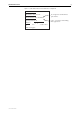
Hardware Reference 5 Figure 1: Serial number label on the underside of a Rapier 24i Model : AT-RP241-10 Part Number: 990-11934-10 N or higher for maximum DS3 performance Product Serial Number: S03K225N Quantity With Unit of Measure: 1 EA 5 Made in Singapore C613-03022-00 REV K J, K, L, or M for less demanding DS3 applications 7 67035 14875
6 Network Service Module Hardware Overview This section provides an overview of the hardware features of NSMs. NSMs are expansion options for switch and router models with an NSM bay. NSMs slot into a base-unit switch or router and either directly provide additional WAN interfaces, or provide expansion slots for Port Interface Cards (PICs). Hardware descriptions for your switch or router, Uplink Modules, and PICs can be found in their respective Hardware References.
Hardware Reference 7 AT-AR040 NSM The AT-AR040 provides four Port Interface Card (PIC) expansion bays for installing PICs. The front panel of the AT-AR040 NSM is shown in Figure 2. The AT-AR040 NSM does not have LEDs.
8 Network Service Module ■ If an AT-AR020 PIC is installed in an AT-AR040 NSM, and operating in E1 mode, you can not install an AT-AR021(S) or AT-AR021(U) PIC in the same row of the NSM. ■ You can install a maximum of four AT-AR027 PICs in an AR745 router fitted with an AT-AR040 NSM. ■ Avoid installing an AT-AR022 or AT-AR026 PIC in an AT-AR040 NSM. Performance of these interfaces may be reduced and packet loss may occur. Interface numbering For each interface type (e.g.
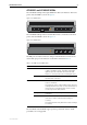
Hardware Reference 9 AT-AR041 and AT-AR042 NSMs The AT-AR041 NSM provides eight ISDN Basic Rate S/T interfaces. The front panel of the AT-AR041 is shown in Figure 3. Figure 3: AT-AR041 NSM 7 6 5 4 3 2 1 0 Active Data The AT-AR042 NSM provides four ISDN Basic Rate S/T interfaces. The front panel of the AT-AR042 is shown in Figure 4. Figure 4: AT-AR042 NSM 3 2 1 0 Active Data The BRI ports use RJ-45 connectors and provide TE interfaces. There are two status LEDs per port.
10 Network Service Module Basic Rate ISDN Interfaces Each Basic Rate S/T interface supports two 64kbit/s B channels and one 16kbit/s D channel, and operates in TE mode only. The switch or router should be configured as a TE for normal operation. User-configurable jumpers provide 100Ω line termination. By default, the jumpers are factory set to terminate Rx and Tx, bridging terminals 2 and 3 (Figure 5 on page 10). To remove the line termination, move the jumpers so that they bridge terminals 1 and 2.
Hardware Reference 11 If you are unsure of whether to terminate the line or not, contact your ISDN service provider or your authorised Allied Telesis distributor or reseller. Warning Do not attempt to change any jumpers on the NSM while the switch or router is connected to a power supply or a live network. Disconnect the mains power supply, any redundant power supply, and any cable attached to the ISDN ports of the NSM.
12 Network Service Module Testing an AT-AR041 or AT-AR042 NSM The Test Facility is built into the AlliedWare operating system, and is the best method to verify the correct operation of the BRI interfaces on the AT-AR041 and AT-AR042 NSMs. Testing can be performed while the switch or router is operational, but any interfaces being tested are dedicated to the Test Facility. For more information about the Test Facility, see the Test Facility chapter of the AlliedWare® Operating System Software Reference.
Hardware Reference 13 Figure 8: Example output from the show test command Board ID Bay Board Name Host Id Rev Serial number ------------------------------------------------------------------------------Base 78 AR740 M1-15 46625812 PIC 38 0 AT-AR023-00 PIC Sync M1-1 5918255 NSM 95 AT-AR041-00 NSM 8BRI P1-3 46624968 Duration Details Interface State Result Type (minutes) Data( %OK ) Control ----------------------------------------------------------------------------eth0 complete good trans 0 TP 1 good(100.
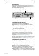
14 Network Service Module AT-AR048 NSM The AR048 NSM provides a single unchannelised DS3 interface with two BNC connectors for transmit and receive. The front panel of the AT-AR048 NSM is shown in Figure 9 and the functions of the LEDs are described in Table 4. Figure 9: AT-AR048 NSM RX TX LOS LOF Loop Activity AIS FERF Table 4: AT-AR048 LEDs LED State Function Active Green Lit when the Line Interface Unit (LIU) is receiving a signal. Loop Green Lit when any loopback is active.
Hardware Reference 15 DS3 Interface Cables Use 75Ω RG59 coaxial cables with BNC connectors. Two cables are required, one for transmit and one for receive. Neither cable should exceed 135m (455feet) in length. Testing an AT-AR048 NSM The Test Facility is built into the AlliedWare operating system, and is the best method to verify the correct operation of the DS3 interface on the AT-AR048 NSM.
16 Network Service Module Figure 11: Example output from the show test interface counter command for a DS3 interface Board ID Bay Board Name Rev Serial number ---------------------------------------------------------------------------Base 114 AT-RP24i Rapier 24i M2-0 41376726 NSM DS3 187 AT-AR048 NSM DS3 M1-1 49986061 Duration Frame Counters Interface State Type (minutes) Tx RxTotal RxGood RxBad -------------------------------------------------------------------------------DS30 complete 4 001045030 001045
Hardware Reference 17 LEDs and What They Mean The following LEDs report operations and faults on NSMs and related hardware: LEDs on the... Are described in ...
18 Network Service Module PIC LEDs The following LEDs report operations and faults on PICs, and may be helpful when diagnosing possible AT-AR040 NSM operational faults. The LEDs are located on the faceplate of the respective PIC. The AT-AR024 ASYN4 PIC does not have LEDs. Table 6: AT-AR020 PRI E1/T1 PIC LEDs LED Function D Data [ISDN mode only] Lit when HDLC packets are being exchanged between the switch or router and the ISDN switch over the D (signalling) channel.
Hardware Reference 19 Table 9: AT-AR023 SYN PIC LEDs LED Function Tx Lit when data is being transmitted over the synchronous interface. Rx Lit when data is being received on the synchronous interface. Table 10: AT-AR026 4ETH PIC LEDs LED Function Left Lit when the port is operating at 100Mbps and full duplex. Right Lit when a link has been established. Flashing when data is being transmitted through the port.
20 Network Service Module Hot Swapping Hot swapping is the installation or removal of a component such as an NSM without powering down or restarting the switch or router. NSMs can be hot swapped in and out of switches and routers that are running Software Version 2.3.1 or later. To find out which software version your switch or router is running, use the command: show system See the Network Service Module Installation and Safety Guide for instructions on how to hot swap your NSM.
Hardware Reference 21 The configuration script is not scanned for commands relating to hot-inserted interfaces until the switch or router is restarted. These interfaces must be configured manually. The switch or router does not update the MAC address of any hot-swapped Ethernet interface until the switch or router is restarted. All other commands that show or set interface properties behave as if swapped out interfaces do not exist. Commands that operate on multiple interfaces skip swapped out interfaces.
22 Network Service Module Troubleshooting This section provides information on how to detect and resolve problems with NSMs. Performing the following tasks will eliminate the most common faults. 1. Check that the NSM is correctly installed. See the Network Service Module Installation and Safety Guide for a step by step guide to installing NSMs. 2. Make sure the power cord is securely connected to the switch or router and the power outlet. 3.
Hardware Reference 23 Obtaining Documentation and Resources Document set The complete document set for Network Service Modules includes: ■ this Hardware Reference, which contains detailed information on the hardware features of Network Service Modules ■ the Network Service Module Installation and Safety Guide, which describes how to install a Network Service Module ■ the Port Interface Card Installation and Safety Guide, which describes how to install a Port Interface Card ■ the Port Interface Car
24 Network Service Module Contacting us With locations covering all of the established markets in North America, Latin America, Europe, Asia, and the Pacific, Allied Telesis provides localized sales and technical support worldwide. To find the representative nearest you, visit us on the Web at www.alliedtelesis.com.