Network Service Module Installation and Safety Guide AT-AR040 AT-AR040-B AT-AR041 AT-AR042 AT-AR048 AT-AR048-B
Network Service Module Installation and Safety Guide AT-AR040 AT-AR040-B AT-AR041 AT-AR042 AT-AR048 AT-AR048-B Download the complete document set from www.alliedtelesis.
2 Network Service Module Network Service Module Installation and Safety Guide Document Number 613-000610 Rev C. © 2007-2008 Allied Telesis, Inc. All rights reserved. No part of this publication may be reproduced without prior written permission from Allied Telesis, Inc. Allied Telesis, Inc. reserves the right to change specifications and other information in this document without prior written notice. The information provided herein is subject to change without notice.
Installation and Safety Guide 3 Contents About this Guide ..................................................................................................................... 4 Compatible Switches and Routers ...................................................................................... 4 Package Contents .................................................................................................................... 5 Hot Swapping ..............................................................
4 Network Service Module About this Guide This Installation and Safety Guide describes how to install the following Network Service Modules (NSMs): ■ AT-AR040 and AT-AR040-B, four Port Interface Card (PIC) expansion bays ■ AT-AR041, eight ISDN Basic Rate S/T interfaces ■ AT-AR042, four ISDN Basic Rate S/T interfaces ■ AT-AR048 and AT-AR040-B, one unchannelised DS3 interface You can download the complete documentation for Network Service Modules from www.alliedtelesis.com/support/software.
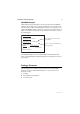
Installation and Safety Guide 5 AT-AR048 Support Maximum DS3 packet forwarding rates are achieved only when the AT-AR048 is installed in a Rapier 48w switch, or a Rapier 24i switch whose serial number ends with the letter N or higher. If maximum DS3 performance is not required, you can install the AT-AR048 in any Rapier 24i whose serial number ends with the letter J or higher. You can find the serial number on the underside of the switch, as shown in the following figure.
6 Network Service Module Hot Swapping There are two methods for installing and removing NSMs: the standard installation method and the hot swap installation method. The software release running on your switch or router determines which of these two methods should be used. If your switch or router is running Software Version 2.2.3 or earlier, follow the standard method. If your switch or router is running Software Version 2.3.1 or later, you can use the hot swap method.
Installation and Safety Guide 7 Installing a Network Service Module Warning Failure to follow this procedure when hot swapping an NSM will cause the switch or router to halt, and may damage it and any files stored in flash memory. 1. Read the safety information. See the Installation and Safety Guide or Safety and Statutory Information Booklet for your switch or router. You can download this document www.alliedtelesis.com/support/software/. 2.
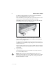
8 Network Service Module If an NSM is already installed, disconnect all network cables and TNV lines before removing the NSM from the switch or router. Remove the NSM by unscrewing both captive screws at the same time. As the captive screws are turned, they will push the NSM out of the bay. If the NSM has extractor levers, moving them to the open position will assist the removal process, as shown in the following figure.
Installation and Safety Guide 6. 9 Slide the NSM into place. Slide the NSM into the NSM bay, making sure the ends of the captive screws are aligned with the screw holes on the switch or router. If the NSM has extractor levers, they should be in the closed position. 7. Secure the NSM. When the NSM has been firmly pushed into place, turn the two captive screws to engage their threads. Tighten both captive screws at the same rate to pull the NSM into position.
10 Network Service Module LEDs and What They Mean The following LEDs report operations and faults on NSMs: ■ “AT-AR041 and AT-AR042 LEDs” on page 10 ■ “AT-AR048 and AT-AR048-B LEDs” on page 11 ■ “Switch and Router LEDs” on page 11 The AT-AR040 and AT-AR040-B NSM units do not have independent LEDs. See “Switch and Router LEDs” on page 11 for information about related LEDs found on the base switch or router.
Installation and Safety Guide 11 AT-AR048 and AT-AR048-B LEDs The following table describes LEDs on the AT-AR048 and AT-AR048-B NSMs. LED State Function Active Green Lit when the Line Interface Unit (LIU) is receiving a signal. Loop Green Lit when any loopback is active. LOS Amber Lit when the received signal is lost. This usually indicates a network disruption, such as a cable being disconnected or a device failure.
Obtaining Documentation and Resources For more information, see: ■ the Installation and Safety Guide for your switch or router ■ the Network Service Module Hardware Reference, which contains detailed information on NSMs and their hardware features ■ the Port Interface Card Installation and Safety Guide, which describes how to install PICs in the AT-AR040 and AT-AR040-B NSMs ■ the Port Interface Card Hardware Reference, which contains detailed information on PICs and their hardware features ■ the Al