
Installation guide


SwitchBlade x8112 Chassis Switch Installation Guide
167
Connectors and Port Pinouts
This section lists the connectors and connector pinouts for the
AT-SBx81GT24 and AT-SBx81GP24 Line Cards.
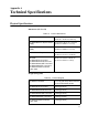
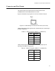
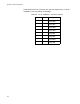
Figure 91 illustrates the pin layout for an RJ-45 connector and port.
Figure 91. Pin Numbering for the RJ-45 Connectors (Front View)
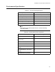
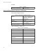
Table 34 lists the RJ-45 pin signals when a twisted-pair port is operating in
the MDI configuration.
Table 35 lists the RJ-45 port pin signals when a twisted-pair port is
operating in the MDI-X configuration.
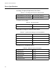
Table 34. MDI Pin Signals (10Base-T or 100Base-TX)
Pin Signal
1TX+
2TX-
3RX+
6RX-
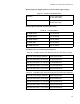
Table 35. MDI-X Pin Signals (10Base-T or 100Base-TX)
Pin Signal
1RX+
2RX-
3TX+
6TX-