CONVERTEON™ Family One-Slot Chassis AT-CV1000 Installation Guide 613-000810 Rev.
Copyright © 2007 Allied Telesis, Inc. All rights reserved. No part of this publication may be reproduced without prior written permission from Allied Telesis, Inc. Allied Telesis is a trademark of Allied Telesis, Inc. Microsoft and Internet Explorer are registered trademarks of Microsoft Corporation. Netscape Navigator is a registered trademark of Netscape Communications Corporation.
Electrical Safety and Emissions Standards This product meets the following standards. U.S. Federal Communications Commission Radiated Energy Note: This equipment has been tested and found to comply with the limits for a Class A digital device pursuant to Part 15 of FCC Rules. These limits are designed to provide reasonable protection against harmful interference when the equipment is operated in a commercial environment.
Translated Safety Statements Important: The indicates that a translation of the safety statement is available in a PDF document titled “Translated Safety Statements” posted on the Allied Telesis website at www.alliedtelesis.com and on the documentation CD shipped with this product.
Contents Preface ..................................................................................................................................................................................9 Safety Symbols Used in this Document................................................................................................................................10 Where to Find Web-based Guides ....................................................................................................................
Contents 6
Figures Figure 1. AT-CV1000 One-Slot Converteon™ Chassis...................................................................................................... Figure 2. AT-CV1000 Chassis Front and Back Panels....................................................................................................... Figure 3. AT-CV5PNL1 Blank Slot Cover ........................................................................................................................... Figure 4. AC Power Adapter...........
Figures 8
Preface This guide contains instructions on how to install an AT-CV1000 One-Slot Converteon™ chassis.
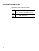
Preface Safety Symbols Used in this Document This document uses the safety symbols defined in Table 1. Table 1. Safety Symbols Symbol 10 Meaning Description Caution Performing or omitting a specific action may result in equipment damage or loss of data. Warning Performing or omitting a specific action may result in electrical shock.
AT-CV1000 One-Slot Chassis Installation Guide Where to Find Web-based Guides The installation and user guides for all Allied Telesis products are available in portable document format (PDF) on our web site at www.alliedtelesis.com. You can view the documents online or download them onto a local workstation or server.
Preface Contacting Allied Telesis This section provides Allied Telesis contact information for technical support as well as sales and corporate information. Online Support You can request technical support online by accessing the Allied Telesis Knowledge Base: www.alliedtelesis.com/support/kb.aspx. You can use the Knowledge Base to submit questions to our technical support staff and review answers to previously asked questions.
Chapter 2 Overview This chapter contains the following sections: “Features” on page 14 “Converteon™ Line Cards” on page 16 “Blank Slot Cover” on page 17 “Power Adapter” on page 18 “Network Topologies” on page 19 13
Chapter 2: Overview Features The AT-CV1000 One-Slot Converteon™ chassis, as shown in Figure 1, is designed to house any single Converteon™ line card. AT -CV 10 00 228 CLASS 1 LASER PRODUCT Figure 1. AT-CV1000 One-Slot Converteon™ Chassis You can install the AT-CV1000 chassis on a desktop as a standalone media converter, mount it on a wall, or install it in an AT-MCR12 chassis. In addition, you can install the AT-CV1000 chassis in an AT-MCR12 media converstion rack-mount chassis.
AT-CV1000 One-Slot Chassis Installation Guide Figure 2 shows the front and back panels of the AT-CV1000 chassis. AT-CV1000 AT-CVPNLx Blank Slot Cover 12VDC AC Power Connector 266 Figure 2.
Chapter 2: Overview Converteon™ Line Cards The AT-CV1000 chassis can only house one Converteon™ line card. The line card is hot swappable. Note For a current list of Converteon™ line cards, refer to the Allied Telesis web site or consult your authorized sales representative. For detailed descriptions of these line cards, refer to the documentation shipped with the line cards and/or the Converteon™ Media Converter Line Cards Reference Guide posted on our web site, www.alliedtelesis.com.
AT-CV1000 One-Slot Chassis Installation Guide Blank Slot Cover The AT-CV5PNL1 blank slot cover is designed to maintain optimal, trouble-free environmental conditions for the AT-CV1000 chassis. An unoccupied line card slot on the AT-CV1000 chassis should be covered with a blank slot cover to keep dust from getting into the chassis and maintain proper airflow, cooling, and ventilation throughout the chassis. Figure 1 illustrates the AT-CV5PNL1 blank slot cover. 222 Figure 3.
Chapter 2: Overview Power Adapter The AT-CV1000 chassis uses a two-part AC power adapter (supplied), as shown in Figure 4. 517 Figure 4.
AT-CV1000 One-Slot Chassis Installation Guide Network Topologies This section describes two network topologies you can create with the Converteon™ Fast and Gigabit media converter line cards installe in an AT-CV1000 chassis. Figure 5 illustrates a standalone topology using one AT-CV1000 chassis with an AT-CM202 line card installed to interconnect two small networks. Network 1 has an AT-FS709FC switch connected to the 100Base-FX port on the AT-CM202 line card in the AT-CV1000 media converter.
Chapter 2: Overview Back-to-Back Topology Figure 6 illustrates a back-to-back topology using two AT-CV1000 chassis, each with an AT-CM202 line card installed to interconnect two small networks. The media converters themselves are connected together through 100Base fiber optic ports on AT-CM202 line cards. Network 1 has an AT-8350GB switch connected to the 10/100Base-TX port on the AT-CM202 line card in the first AT-C1000 media converter.
Chapter 3 Installation This chapter contains the following installation procedures for the AT-CV1000 chassis: “Reviewing Safety Precautions” on page 22 “Selecting a Site for the Chassis” on page 23 “Unpacking the Chassis” on page 24 “Using the AT-CV1000 Chassis on a Desktop” on page 25 “Mounting the AT-CV1000 Chassis on a Wall” on page 26 “Installing an AT-CV1000 Chassis in an AT-MCR12 Rack-Mount Chassis” on page 28 “Installing a Converteon™ Line Card” on page 32 “Powering O
Chapter 3: Installation Reviewing Safety Precautions Please review the following safety precautions before you begin to install the chassis or any of its components. Note The indicates that a translation of the safety statement is available in a PDF document titled “Translated Safety Statements” on the Allied Telesis website at www.alliedtelesis.com and on the documentation CD shipped with this product. Warning: Do not work on equipment or cables during periods of lightning activity.
AT-CV1000 One-Slot Chassis Installation Guide Selecting a Site for the Chassis Observe the following requirements when choosing a site for the chassis: The power outlet for the chassis should be located near the unit and should be easily accessible. The site should provide easy access to the ports on the front and the power supply on the back of the chassis. This arrangement will make it easy for you to connect and disconnect cables as well as to view the LEDs.
Chapter 3: Installation Unpacking the Chassis To unpack the chassis, perform the following procedure: 1. Remove all components from the shipping package. Note Store the packaging material in a safe location. You must use the original shipping material if you need to return the unit to Allied Telesis. 2. Make sure that the following components are included in the package. If any item is missing or damaged, contact your Allied Telesis sales representative for assistance.
AT-CV1000 One-Slot Chassis Installation Guide Using the AT-CV1000 Chassis on a Desktop To use the AT-CV1000 chassis on a desktop, perform the following procedure: 1. Remove the chassis from the shipping container. 2. Turn the chassis over and place it on a secure surface. 3. Attach the four self-adhesive rubber feet, included, to the bottom of the chassis, as shown in Figure 7. 262 AT-CV1000 Figure 7. Attaching Rubber Feet 4. Turn the chassis over again. 5.
Chapter 3: Installation Mounting the AT-CV1000 Chassis on a Wall The AT-CV1000 chassis is shipped with two wall-mounting brackets. The chassis is designed to be mounted vertically on a wall using the keyholes on the wall-mounted brackets. To mount the AT-CV1000 chassis on a wall, perform the following procedure: 1. If attached, remove the rubber feet, data cables, and power cord from the chassis. 2. Install the line card according to the instructions in “Installing a Converteon™ Line Card” on page 32.
AT-CV1000 One-Slot Chassis Installation Guide 6. Install two plastic anchors and two screws onto the wall, as illustrated in Figure 9. -C T A V 1 0 0 0 LK 2 20 M C TA AT S F P LK AT T FD X S 1 UCT AS CL PROD R SE LA R M DY S L M L M A O 295 Figure 9. Installing the Plastic Anchors and Screws Onto the Wall 40-6 0V DC L Y D SM M L A O M 7. Position the chassis vertically onto the wall screws, as illustrated in Figure 10, and slide it down to secure the brackets against the wall.
Chapter 3: Installation Installing an AT-CV1000 Chassis in an AT-MCR12 Rack-Mount Chassis In order to install the AT-CV1000 chassis in an AT-MCR12 rack-mount chassis, an AT-CVMCR Installation Adapter, as shown in Figure 11, is required. Note For detailed descriptions and installation procedures for the AT-MCR12 rack-mount chassis, refer to the AT-MCR12 Media Conversion Rack-Mount Chassis Installation Guide available on the Allied Telesis website, www.alliedtelesis.com. 293 Figure 11.
AT-CV1000 One-Slot Chassis Installation Guide the AT-CV1000 chassis and loosen the captive screw to remove the mounting rail from that slot, as shown in Figure 12. MEDIA CONVERTER RACKMOUNT CHASSIS MCR12 MEDIA AASIS UNT CH ACKMO RTER R CONVE PWR A PWR B 1251 Figure 12. Removing the Mounting Rail from a Slot in the AT-MCR12 Chassis 2. Turn the AT-CV1000 chassis upside down. CLASS 1 LASER PRODUCT 3.
Chapter 3: Installation 4. Turn the chassis over, as shown Figure 14. RDY 1266 Figure 14. AT-CV1000 Chassis with AT-CVMCR Adapter Installed 5. Use the thumb tab on the adapter to slide the AT-CV1000 chassis into the AT-MCR12 chassis, as shown in Figure 15. MEDIA CONVERTER RACKMOUNT CHASSIS MCR12 CO MEDIA NVERTE MOUN R RACK T CHAA SIS 020 MCV2100 ATAT-C AT PWR A LK PWR B F X LK AT FD 1252 T X RDY SML ML OAM Figure 15. Sliding the AT-CV1000 into the AT-MCR12 Chassis Slot 6.
AT-CV1000 One-Slot Chassis Installation Guide 7. Tighten the captive screw on the AT-CVMCR adapter to secure the AT-CV1000 in the chassis, as shown in Figure 16. MEDIA CONVERTER RACKMOUNT CHASSIS MCR12 MEDIA CKMOUN TER RA CONVER T CHAA SIS V10002 AT-C M20 C AT- LK PWR A AT PWR B F X LK AT FD 1253 T X RDY SML ML OAM Figure 16. Tightening the Captive Screw on the AT-CVMCR Adapter 8. Install the line card according to the instructions in “Installing a Converteon™ Line Card” on page 32.
Chapter 3: Installation Installing a Converteon™ Line Card To install a Converteon™ line card, perform the following procedure: Caution Be sure to observe all standard electrostatic discharge (ESD) precautions, such as wearing an antistatic wrist strap, to avoid damaging the device. A line card can be damaged by static electricity. 1. Remove the Converteon™ line card from its shipping package and store the package in a safe place.
AT-CV1000 One-Slot Chassis Installation Guide 4. Locate the alignment guides on both sides of the slot, as shown in Figure 17. AT-CV1000 Alignment Guides 505 Figure 17. Location of the Alignment Guides 5. Align the back edge of the line card with the left and right alignment guides located inside the slot. 6. Slide the line card into the slot, as shown in Figure 18, until the slot cover is flush with the front of the chassis.
Chapter 3: Installation 7. Use a Phillips screwdriver to tighten the captive screw on the line card, as shown in Figure 19. AT -CV 10 00 ATCM 202 LK AT CLASS 1 LASER PRODUCT LK AT FD RD Y SM L M L OA M 501 Figure 19. Tightening the Captive Screw Note Always tighten the captive screw to secure the line card to the chassis. Refer to the documentation shipped with your line card, or to the Converteon™ Media Converter Line Cards Reference Guide for cabling information.
AT-CV1000 One-Slot Chassis Installation Guide Powering On an AT-CV1000 Chassis The AC power adapter for the AT-CV1000 chassis consists of two parts: a power cord and a power adapter. Note The power adapter for the AT-CV1000 chassis is not used if the chassis is installed in an AT-MCR12 rack-mount chassis. Note Use only power sources that are UL Listed (QQGQ or EPBU), TUV Licensed or other Safety Agencies approved, and that are suitable for country of use.
Chapter 3: Installation The chassis is now ready for network operations. Warning: Power cord is used as a disconnection device. To deenergize equipment, disconnect the power cord. E3 Pluggable Equipment. The socket outlet shall be installed near the equipment and shall be easily accessible.
AT-CV1000 One-Slot Chassis Installation Guide Installing a Blank Slot Cover The AT-CV1000 chassis is shipped with the line card slot covered with the AT-CV5PNL1 blank slot cover. When the line card slot is unoccupied, you should cover it with a blank slot cover, to keep dust from getting into the chassis and to maintain proper airflow, cooling, and ventilation throughout the chassis.
Chapter 3: Installation 6. Use a Phillips screwdriver to tighten the captive screw, as shown in Figure 22. AT -CV 10 00 CLASS 1 LASER PRODUCT 506 Figure 22. Tightening the Captive Screw on an AT-CV5PNL1 Blank Slot Cover Note Always tighten the captive screw to secure the blank slot cover to the chassis.
AT-CV1000 One-Slot Chassis Installation Guide Warranty Registration 39
Chapter 3: Installation Warranty Registration Allied Telesis hardware products are covered under limited warranties. Some products have a longer warranty coverage than others. The AT-CV1000 chassis has a limited warranty of Lifetime (24 months Fan & PSU). All Allied Telesis warranties are subject to the terms and conditions set out on the Allied Telesis website at www.alliedtelesis.com/warranty.
Appendix A Technical Specifications Physical Specifications Dimensions: WxDxH 10.48 cm x 17.77 cm x 2.54 cm (4.125 in x 7.0 in x 1.0 in) Environmental Specifications Operating Temperature: 0° C to 40° C (32° F to 104° F) Storage Temperature: -25° C to 70° C (-13°F to 158° F) Operating Humidity: 5% to 90% non-condensing Storage Humidity: 5% to 95% non-condensing Maximum Operating Altitude: 3,000 m (10,000 ft.) Maximum Storage Altitude: 4,000 m (13,100 ft.
Appendix A: Technical Specifications Safety and Electromagnetic Emissions Certifications 42 EMI: FCC Class A, EN55022 Class A, VCCI Class A, C-TICK, CE Immunity: EN55024 Safety: UL60950-1 (CULUS), EN60950-1 (TUV), CAN/CSA C22.2 No. 60950-1 Laser: EN60825 Quality and Reliability: MTBF > 100,000 hrs.