
User Guide

Chapter 1: Overview
32
AT-FAN06 Fan Module
Installation of two AT-FAN06 fan modules are required in the
AT-DC2552XS. Each AT-FAN06 fan module is equipped with two, forced
air cooling fans The fans push air through the chassis from the front to the
rear. The AT-FAN06 fan module is ordered and shipped separately from
the AT-DC2552XS L2 Data Center Switch.
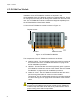
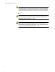
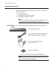
A view of the AT-FAN06 fan module is shown in Figure 10.
Figure 10. AT-FAN06 Fan Module
The components of the AT-FAN06 fan module are as follows:
Captive screws - The two captive screws secure the fan module to
the chassis frame. See “AT-FAN06 Fan Module” on page 32 for
the fan installation procedure.
Handles - The two handles are used to physically push or pull the
AT-FAN06 fan module into and out of the chassis. See “AT-FAN06
Fan Module” on page 32 the fan installation procedure.
Intake Air Vents - The AT-FAN06 fan module has two fans which
pull air through the intake air vents to cool the chassis
components. The air is discharged through the rear panel exhaust
air vents. See Figure 2 on page 20 for the location of the exhaust
vents.
Warning
On both the AT-PWR06 power supply module and AT-FAN06 fan
modules, keep the intake vents clear of any obstructions to insure
proper cooling of the switch components.
Captive Screws
Intake Air VentsHandles