AT-FS705LE Fast Ethernet Switch Installation Guide PN 613-50138-00 Rev D
Copyright © 2003 Allied Telesyn, Inc. 960 Stewart Drive, Suite B, Sunnyvale, CA 94085, USA All rights reserved. No part of this publication may be reproduced without prior written permission from Allied Telesyn, Inc. Ethernet is a registered trademark of Xerox Corporation. All other product names, company names, logos or other designations mentioned herein are trademarks or registered trademarks of their respective owners. Allied Telesyn, Inc.
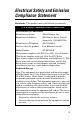
Electrical Safety and Emission Compliance Statement Standards: This product meets the following standards. U.S. Federal Communications Commission Declaration Of Conformity Manufacturer Name: Allied Telesyn, Inc.
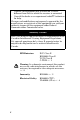
- Connect the equipment into an outlet on a circuit different from that to which the receiver is connected. - Consult the dealer or an experienced radio/TV technician for help. Changes and modifications not expressly approved by the manufacturer or registrant of this equipment can void your authority to operate this equipment under Federal Communications Commission rules. Industry Canada This Class B digital apparatus meets all requirements of the Canadian Interference-Causing Equipment Regulations.
Important: Appendix A contains translated safety statements for installing this equipment. When you see the , go to Appendix A for the translated safety statement in your language. Wichtig: Anhang A enthält übersetzte Sicherheitshinweise für die Installation dieses Geräts. Wenn Sie sehen, schlagen Sie in Anhang A den übersetzten Sicherheitshinweis in Ihrer Sprache nach. Vigtigt: Tillæg A indeholder oversatte sikkerhedsadvarsler, der vedrører installation af dette udstyr.
Importante: El Apéndice A contiene mensajes de seguridad traducidos para la instalación de este equipo. Cuando vea el símbolo , vaya al Apéndice A para ver el mensaje de seguridad traducido a su idioma. Obs! Bilaga A innehåller översatta säkerhetsmeddelanden avseende installationen av denna utrustning. När du ser , skall du gå till Bilaga A för att läsa det översatta säkerhetsmeddelandet på ditt språk.
Table of Contents Electrical Safety and Emission Compliance Statement ...............................iii Table of Contents ........................................ vii Welcome to Allied Telesyn ......................... ix Where to Find Related Guides........................ ix Document Conventions ................................... ix Contacting Allied Telesyn ............................... xi Online Support ......................................... xi E-mail and Telephone Support................
Table of Contents Standalone Topology ............................... 12 Back-to-Back Topology............................ 13 Chapter 2 Installation ................................................... 15 Verifying the Package Contents .................... 15 Selecting a Site ........................................ 16 Reviewing Safety Guidelines .................. 17 Installing the Switch on a Table or Desktop. 19 Wall-Mounting the Switch ............................. 22 Warranty Registration .............
Welcome to Allied Telesyn This guide contains instructions on how to install the AT-FS705LE Fast Ethernet Switch. Where to Find Related Guides The Allied Telesyn web site at www.alliedtelesyn.com offers you an easy way to access the most recent documentation, software, and technical information for all of our products. For product guides, select “Support & Services” from our web site. Document Conventions This guide uses the following conventions: Note A note provides additional information.
Welcome to Allied Telesyn Caution Cautions informs you that performing or omitting a specific action may result in equipment damage or loss of data. Warning Warnings informs you that performing or omitting a specific action may result in bodily injury.
AT-FS705LE Installation Guide Contacting Allied Telesyn This section provides Allied Telesyn contact information for technical support as well as sales or corporate information. Online Support You can request technical support online by accessing the Allied Telesyn Knowledge Base from the following web site: http://kb.alliedtelesyn.com. You can use the Knowledge Base to submit questions to our technical support staff and review answers to previously asked questions.
Welcome to Allied Telesyn To obtain a RMA number, contact Allied Telesyn’s Technical Support at our web site: http://www.alliedtelesyn.com. For Sales or Corporate Information You can contact Allied Telesyn for sales or corporate information at our web site: http://www.alliedtelesyn.com. To find the contact information for your country, select “Contact Us” then “Worldwide Contacts.
Chapter 1 Overview The AT-FS705LE Fast Ethernet Switch is a 10Base-T/100Base-TX unmanaged switch. The switch provides you with a simple, cost-effective solution for Ethernet switching between endnodes operating at either 10 Mbps or 100 Mbps. Figure 1 and Figure 2 show the front and back panels of the switch.
Overview Figure 2 AT-FS705LE Back Panel Key Features The AT-FS705LE switch has the following features: ❑ Non-blocking architecture ❑ Five Auto-Negotiating 10/100 Mbps twisted pair ports with RJ-45 connectors wired as MDI-X ❑ One Auto-Negotiating 10/100 Mbps uplink twisted pair port with RJ-45 connector wired as MDI. This port is used to connect the AT-FS705LE switch to another switch or hub without a crossover cable. ❑ External AC/DC power adapter ❑ MAC address table with a capacity of 2,000 addresses.
AT-FS705LE Installation Guide Physical Description The physical description for the switch includes: ❑ Ports 1 through 4 ❑ Port 5 and the Uplink port ❑ LEDs ❑ Power Supply ❑ MAC Address Table Ports 1 Through 4 Ports 1 through 4 can operate at either 10 Mbps or 100 Mbps and in either half- or full-duplex mode. The ports, featuring RJ-45 connectors, are configured as MDI-X, meaning that you can connect a workstation or server to one of the ports without using a crossover cable.
Overview Note In order for a twisted pair port on the AT-FS705LE switch to successfully AutoNegotiate its duplex mode with an endnode, the end-node should also be using Auto-Negotiation. Otherwise, a duplex mode mismatch can occur. The twisted pair port, using Auto-Negotiation, will default to half-duplex if it detects that the end-node is not using AutoNegotiation. This will result in a mismatch if the end-node is operating at a fixed duplex mode of full-duplex.
AT-FS705LE Installation Guide Both Port 5 and the Uplink port offer 10 Mbps or 100 Mbps performance and Auto-Negotiation operation for both speed and duplex mode. Both ports feature a RJ-45 connector and have a maximum operating distance of 100 meters (328 feet) using Category 5 cable. Note You can use either Port 5 or the Uplink port, but you cannot use both simultaneously. Status LEDs Refer to Table 1 for a description of the switch’s LEDs.
Overview Table 1 LEDs (continued) LEDs Color Description LINK/ACT Green A valid link has been established on the port. Flashing Data is being transmitted or received on the port. Green The port is operating in full-duplex mode. OFF The port is operating in half-duplex mode.
AT-FS705LE Installation Guide The AT-FS705LE switch features auto MDI/ MDI/X on all ports. Auto MDI/MDI-X automatically determines the configuration of the port on the end-node to which it is connected and then configures itself appropriately. For example, if a port on a switch is connected to a port on a bridge, which typically wired as MDI, the port on the switch automatically configures itself as MDI-X.
Overview Each twisted pair port on the AT-FS705LE switch can operate in either half-duplex or fullduplex mode. Since these twisted pair ports are IEEE 802.3u-compliant, the duplex mode can be set automatically through Auto-Negotiation. With Auto-Negotiation, if the end-node is capable of full-duplex, the port is set automatically to full-duplex mode. If the endnode is capable of half-duplex, the port is set automatically to half-duplex mode.
AT-FS705LE Installation Guide MAC Address Table The heart of an Ethernet switch is the Media Access Control (MAC) address table. Every device that you attach to an Ethernet network has a MAC address. This address is assigned to the device by the device’s manufacturer. For example, each Network Interface Card (NIC) that you install into your network computers has a MAC address that was assigned to it by the card’s manufacturer.
Overview The switch also checks the destination MAC address of each frame it receives. The destination address is the MAC address of the end-node to which the frame is intended. If the address is in the table, the switch directs the frame directly to the port where the end-node is located. This helps to ensure that end-nodes will only receive traffic that is intended for them and not have to deal with traffic intended for other end-nodes.
AT-FS705LE Installation Guide from the table if it does not see a frame from the end-node with the address on any port after five minutes (300 seconds). The aging timer also helps to ensure that the table is correct should an end-node be moved from one port on the switch to another port. External Power Supply The AT-FS705LE switch uses an external AC/ DC power adapter that comes standard with the switch.
Overview Network Topologies The AT-FS705LE switch can be used in a variety of network topologies, such as standalone or back-to-back. Both topologies are described below. Standalone Topology Figure 3 illustrates a network of one ATFS705LE switch used to interconnect four workstations and a server. In this configuration, the Uplink port is not used.
AT-FS705LE Installation Guide Back-to-Back Topology Figure 4 illustrates a network of two AT-FS705LE switches that have been interconnected using one of the Uplink ports on one of the units. Using the Uplink port eliminates the need for a crossover cable to interconnect the switches.
Chapter 2 Installation This section contains the procedures for installing the switch. Verifying the Package Contents Make sure the following items are included in your package. If any item is missing or damaged, contact your Allied Telesyn sales representative for assistance.
Installation Note For wall-mount installation, the screws, plastic anchors, and any other material necessary to physically mount the switch to the wall are not provided. Selecting a Site Be sure to observe the following requirements when choosing a site for your switch. ❑ Make sure you are placing the switch in a dust-free and moisture-free environment. ❑ Do not block the ventilation openings on the unit. Allow at least 10 centimeters (4 inches) of space at the front and back of the unit for ventilation.
AT-FS705LE Installation Guide Observe the following cabling specifications: Ports Connector Type Type of Cable Maximum Distance 1 through 5 RJ-45 Category 5 100 m (328 ft) Uplink RJ-45 Category 5 100 m (328 ft) Reviewing Safety Guidelines Please review the following safety guidelines before installing the switch. Warning Power cord is used as a disconnection device. To de-energize equipment, disconnect the power cord.
Installation Caution Air vents: The air vents must not be blocked on the unit and must have free access to the room ambient air for cooling. 7 Caution Operating Temperature: This product is designed for a maximum ambient temperature of 40°C. 8 Caution All Countries: Install this product in accordance with local and National Electric Codes. 9 Caution Europe - EU: Use TÜV licensed AC adapter of DC 7.5V, 1A. USA/Canada: Use a UL Listed/CSA Certified AC adapter of DC 7.5V, 1A.
AT-FS705LE Installation Guide Installing the Switch on a Table or Desktop To install the switch on a table or desktop, perform the following procedure: 1. Remove all the items from the packaging and store the packaging material in a safe place. In the event a problem occurs and you need to return the unit, please use as much of the original shipping material as possible. 2. Attach the four protective rubber feet to the bottom of the switch, as illustrated in Figure 1. Figure 1 Attaching the Rubber Feet 3.
Installation Note You can use either Port 5 or the Uplink port, but you cannot use both simultaneously. When connecting a twisted pair cable to a port, observe the following guidelines: • • • An RJ-45 connector should fit snugly into the port on the switch. The tab on the connector should lock the connector into place. You should check to be sure that you are using the appropriate type of twisted pair cabling. Refer to Table 4 on page 10 for twisted pair cable specifications.
AT-FS705LE Installation Guide Warning The power cord is used as a disconnection device. To de-energize equipment, disconnect the power cord. 5 6. Verify that either the PWR LED is green. If the LED is OFF, refer to “Troubleshooting” on page 27 for instructions. Note The switch perform a self-diagnostic test upon power up. This takes about 20 seconds to complete. 7. Power ON the end-nodes connected to the switch. 8. Check that all the LINK/ACT LEDs are green.
Installation Wall-Mounting the Switch The switch can be mounted vertically or horizontally on a wall using the keyholes on the bottom of the switch. Except for the plastic anchors, the screws and other materials necessary to mount the switch on a wall are not provided. To wall-mount the switch, perform the following procedure: 1. If attached, remove the rubber feet, data cables, and power cord from the switch. 2. Select a wall location for the switch. 3.
AT-FS705LE Installation Guide 4. Position the switch onto the wall screws, as illustrated in . Figure 3 Positioning the Switch Onto the Wall Screws 5. Connected the twisted pair cables to the twisted pair ports. Note You can use either Port 5 or the Uplink port, but you cannot use both simultaneously. When connecting a twisted pair cable to a port, observe the following guidelines: • An RJ-45 connector should fit snugly into the port on the switch.
Installation • • You should check to be sure that you are using the appropriate type of twisted pair cabling. Refer to Table 4 on page 10 for twisted pair cable specifications. Since the twisted pair port, when operating in Auto-Negotiation, is Auto MDI/MDI-X, you can use either a straight-through or crossover twisted pair cable to connect any type of network device to a port on the switch. If you disable Auto-Negotiation on the port, the port defaults to MDI-X. 6.
AT-FS705LE Installation Guide Note The switch perform a self-diagnostic test upon power up. This takes about 20 seconds to complete. 8. Power ON the end-nodes connected to the switch. 9. Check that all the LINK/ACT LEDs are green. If any of the LEDs is OFF, refer to “Troubleshooting” on page 27 for instructions. The switch is now ready for use.
Installation Warranty Registration When you have finished installing the product, register your product by completing the enclosed warranty card and sending it in. You can also fill out the registration online by selecting “Warranties” under “Support & Services” from www.alliedtelesyn.com.
Chapter 3 Troubleshooting Follow the guidelines below to test and troubleshoot the installation in the event a problem occurs. If the PWR LED is OFF, do the following: ❑ Check to be sure that the power adapter is securely connected to the power source and to the DC connector on the front of the AT-FS705LE switch. ❑ Check to be sure that the power outlet has power by connecting another device to it. ❑ Try replacing the power adapter with another power adapter.
Troubleshooting If the LINK/ACT LED is OFF, do the following: ❑ Check to be sure that the end-node connected to the port on the switch is powered ON. If the end-node is OFF, power the unit ON. ❑ Check that the cable is securely connected to the port on the switch and on the endnode. ❑ Check to be sure that the distance between the switch and the end-node does not exceed 100 meters (328 feet). ❑ Check to be sure that you are using Category 5 cable.
Appendix A Technical Specifications Physical Dimensions: WxDxH 100 x 78.5 x 26 mm (3.93 x 3.09 x 1.
Technical Specifications Electrical Rating Input Supply Voltage: 7.5V Power Current: 1A Maximum Power Consumption: 8W Maximum Standards & Compliance IEEE 802.3 10T Ethernet IEEE 802.
AT-FS705LE Installation Guide Pinout Assignments Figure 5 shows the pinout assignments for the RJ-45 connector. 1 8 8 1 Figure 1 RJ-45 Pin Assignments Table 5 lists the 10Base-T/100Base-TX connector pins and their signals when the port is operating in either MDI or MDI-X configuration.
Appendix B Translated Safety and Emission Information Important: This appendix contains multiplelanguage translations for the safety statements in this guide. Wichtig: Dieser Anhang enthält Übersetzungen der in diesem Handbuch enthaltenen Sicherheitshinweise in mehreren Sprachen. Vigtigt: Dette tillæg indeholder oversættelser i flere sprog af sikkerhedsadvarslerne i denne håndbog. Belangrijk: Deze appendix bevat vertalingen in meerdere talen van de veiligheidsopmerkingen in deze gids.
Translated Safety and Emission Information Viktig: Dette tillegget inneholder oversettelser til flere språk av sikkerhetsinformasjonen i denne veiledningen. Importante: Este anexo contém traduções em vários idiomas das advertências de segurança neste guia. Importante: Este apéndice contiene traducciones en múltiples idiomas de los mensajes de seguridad incluidos en esta guía. Obs! Denna bilaga innehåller flerspråkiga översättningar av säkerhetsmeddelandena i denna handledning.
AT-FS705LE Installation Guide Standards: This product meets the following standards: U.S. Federal Communications Commission Declaration Of Conformity Manufacturer Name: Allied Telesyn, Inc. Manufacturer Address: 960 Stewart Drive, Suite B Sunnyvale, CA 94085 USA Manufacturer Telephone: 408-730-0950 Declares that the product: Fast Ethernet Switch Model Number: AT-FS705LE This product complies with FCC Part 15B, Class B Limits: This device complies with part 15 of the FCC Rules.
Translated Safety and Emission Information Changes and modifications not expressly approved by the manufacturer or registrant of this equipment can void your authority to operate this equipment under Federal Communications Commission rules. Industry Canada This Class B digital apparatus meets all requirements of the Canadian Interference-Causing Equipment Regulations. Cet appareil numérique de la classe B respecte toutes les exigences du Règlement sur le matériel brouilleur du Canada.
AT-FS705LE Installation Guide 10 Europe - EU: Use TÜV licensed AC adapter of DC 7.5V, 1A. USA/Canada: Use a UL Listed/CSA Certified AC adapter of DC 7.5V, 1A.
Translated Safety and Emission Information Normen: Dieses Produkt erfüllt die Anforderungen der nachfolgenden Normen. 1 Hochfrequenzstörung 2 Warnung: Bei Verwendung zu Hause kann dieses Produkt Funkstörungen hervorrufen. In diesem Fall müßte der Anwender angemessene Gegenmaßnahmen ergreifen.
AT-FS705LE Installation Guide Standarder: Dette produkt tilfredsstiller de følgende standarder. 1 Radiofrekvens forstyrrelsesemission: FCC Klasse B EN55022 Klasse B VCCI Klasse B C-TICK 2 Advarsel: I et hjemligt miljø kunne dette produkt forårsage radio forstyrrelse. Bliver det tilfældet, påkræves brugeren muligvis at tage tilstrækkelige foranstaltninger.
Translated Safety and Emission Information Eisen: Dit product voldoet aan de volgende eisen. 1 RFI Emissie 2 Waarschuwing: Binnenshuis kan dit product radiostoring veroorzaken, in welk geval de gebruiker verplicht kan worden om gepaste maatregelen te nemen. 3 Immuniteit EN55024 4 Electrische Veiligheid EN60950 (TUV) UL60950 (cULus) FCC Klasse B EN55022 Klasse B VCCI Klasse B C-TICK Veiligheid 5 Waarschuwing: Het toestel wordt uitgeschakeld door de stroomkabel te ontkoppelen.
AT-FS705LE Installation Guide Normes: ce produit est conforme aux normes de suivantes. 1 Emission d’interférences radioélectriques FCC Classe B EN55022 Classe B VCCI Classe B C-TICK 2 Mise En Garde: Dans un environnement domestique, ce produit peut provoquer des interférences radioélectriques. Auquel cas, l’utilisateur devra prendre les mesures adéquates.
Translated Safety and Emission Information Standardit: Tämä tuote on seuraavien standardien mukainen. 1 Radioaaltojen häirintä 2 Varoitus: Kotiolosuhteissa tämä laite voi aiheuttaa radioaaltojen häiröitä, missä tapauksessa laitteen käyttäjän on mahdollisesti ryhdyttävä tarpeellisiin toimenpiteisiin. 3 Kestävyys EN55024 4 Sähköturvallisuus EN60950 (TUV) UL60950 (cULus) FCC Luokka B EN55022 Luokka B VCCI Luokka B C-TICK Turvallisuus 5 Huomautus: Virtajohtoa käytetään virrankatkaisulaitteena.
AT-FS705LE Installation Guide Standard: Questo prodotto è conforme ai seguenti standard. 1 Emissione RFI (interferenza di radiofrequenza) FCC Classe B EN55022 Classe B VCCI Classe B C-TICK 2 Avvertenza: in ambiente domestico questo prodotto potrebbe causare radio interferenza. In questo caso potrebbe richiedersi all’utente di prendere gli adeguati provvedimenti.
Translated Safety and Emission Information Sikkerhetsnormer: Dette produktet tilfredsstiller følgende sikkerhetsnormer. 1 RFI stråling 2 Advarsel: Hvis dette produktet benyttes til privat bruk, kan produktet forårsake radioforstyrrelse. Hvis dette skjer, må brukeren ta de nødvendige forholdsregler. 3 Immunitet EN55024 4 Elektrisk sikkerhet EN60950 (TUV) UL60950 (cULus) FCC Klasse B EN55022 Klasse B VCCI Klasse B C-TICK Sikkerhet 5 Forsiktig: Strømledningen brukes til å frakoble utstyret.
AT-FS705LE Installation Guide Padrões: Este produto atende aos seguintes padrões. 1 Emissão de interferência de radiofrequência FCC Classe B EN55022 Classe B VCCI Classe B C-TICK 2 Aviso: Num ambiente doméstico este produto pode causar interferência na radiorrecepção e, neste caso, pode ser necessário que o utente tome as medidas adequadas.
Translated Safety and Emission Information Estándares: Este producto cumple con los siguientes estándares. 1 Emisión RFI 2 Advertencia: en un entorno doméstico, este producto puede causar radiointerferencias, en cuyo caso, puede requerirse del usuario que tome las medidas que sean convenientes al respecto.
AT-FS705LE Installation Guide Standarder: Denna produkt uppfyller följande standarder. 1 Radiostörning 2 Varning: Denna produkt kan ge upphov till radiostörningar i hemmet, vilket kan tvinga användaren till att vidtaga erforderliga åtgärder. 3 Immunitet EN55024 4 Elsäkerhet EN60950 (TUV) UL60950 (cULus) FCC Klass B EN55022 Klass B VCCI Klass B C-TICK Säkerhet 5 Varning: Nätkabeln används som strömbrytare för att koppla från strömmen, dra ur nätkabeln. 6 Utrustning Med Plugg.