AT-FS970M Series Fast Ethernet Switch Management Software Web Interface User’s Guide AT-FS970M Series Version 2.3.1.0 613-001946 Rev.
Copyright Copyright © 2014, Allied Telesis, Inc. All rights reserved. This product includes software licensed under the BSD License. As such, the following language applies for those portions of the software licensed under the BSD License: Redistribution and use in source and binary forms, with or without modification, are permitted provided that the following conditions are met: * Redistributions of source code must retain the above copyright notice, this list of conditions and the following disclaimer.
Allied Telesis is committed to meeting the requirements of the open source licenses including the GNU General Public License (GPL) and will make all required source code available. If you would like a copy of the GPL source code contained in this product, please send us a request by registered mail including a check for US$15 to cover production and shipping costs, and a CD with the GPL code will be mailed to you. GPL Code Request Allied Telesis, Inc.
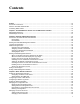
Contents Preface ............................................................................................................................................................ 15 Document Conventions .................................................................................................................................... 16 Where to Find Web-based Guides ................................................................................................................... 17 Contacting Allied Telesis .
Contents Changing the User Privilege....................................................................................................................... 54 Deleting a User Account............................................................................................................................. 55 Rebooting a Switch ........................................................................................................................................... 57 Upgrading the Software ...............
AT-FS970M Series Version 2.3.1.0 Web Interface User’s Guide Port VLAN Identifier ................................................................................................................................. 132 Tagged VLANs......................................................................................................................................... 132 Tagged and Untagged Ports ....................................................................................................................
Contents Adding a RADIUS Server .........................................................................................................................193 Configuring TACACS+ for Remote Manager Authentication ..........................................................................195 Configuring Remote Manager Authentication Using TACACS+...............................................................195 Adding a TACACS+ Server ............................................................................
AT-FS970M Series Version 2.3.1.0 Web Interface User’s Guide Assigning a QoS Policy to Ports..................................................................................................................... 260 Displaying a List of QoS Policies.................................................................................................................... 262 Chapter 23: Setting Dynamic Routes Using RIP ......................................................................................
Contents 10
Figures Figure 1: Login Page ............................................................................................................................................................26 Figure 2: Login Page with Entries.........................................................................................................................................27 Figure 3: Dashboard Page .............................................................................................................................
Figures Figure 51: VLANs Page ......................................................................................................................................................134 Figure 52: Add VLAN Page ................................................................................................................................................135 Figure 53: Edit VLAN Page..................................................................................................................................
AT-FS970M Series Version 2.3.1.0 Web Interface User’s Guide Figure 111: Traffic Classifiers Page....................................................................................................................................262 Figure 112: Layer 3 Tab .....................................................................................................................................................265 Figure 113: RIP Configuration Page.....................................................................
Figures 14
Preface This is the web interface user’s guide for the AT-FS970M Series of Fast Ethernet switches. The instructions in this guide explain how to start a management session, use the web interface of the AlliedWare Plus™ Management Software, and configure the features of the switch. For hardware installation instructions, refer to the AT-FS970M Series Fast Ethernet Switches Installation Guide.
Document Conventions This document uses the following conventions: Note Notes provide additional information. Caution Cautions inform you that performing or omitting a specific action may result in equipment damage or loss of data. Warning Warnings inform you that performing or omitting a specific action may result in bodily injury.
AT-FS970M Series Version 2.3.1.0 Web Interface User’s Guide Where to Find Web-based Guides The installation and user guides for all of the Allied Telesis products are available for viewing in portable document format (PDF) from our web site at www.alliedtelesis.com/support/documentation.
Contacting Allied Telesis If you need assistance with this product, you may contact Allied Telesis technical support by going to the Support & Services section of the Allied Telesis web site at www.alliedtelesis.com/support. You can find links for the following services on this page: 24/7 Online Support— Enter our interactive support center to search for answers to your product questions in our knowledge database, to check support tickets, to learn about RMAs, and to contact Allied Telesis experts.
Chapter 1 AT-FS970M Series Version 2.3.1.0 Web Browser Interface This chapter describes the types of management sessions using the AT-FS970M Series management software and the web interface manager accounts.
Chapter 1: AT-FS970M Series Version 2.3.1.0 Web Browser Interface Management Sessions The AT-FS970M Series switches provide two management interfaces: the web interface and Command Line Interface (CLI). This manual provides procedures that guide you through the web interface. The initial management session of the switch can be from a management session, either through the web interface or the CLI.
AT-FS970M Series Version 2.3.1.0 Web Interface User’s Guide Web Manager Accounts You must log on to manage the switch. This requires a valid username and password. The switch comes with one manager account with a username of “manager” and the default password of “friend.” Both the username and password are case-sensitive. This account gives you access to all management modes and commands. In the web interface, you can create two additional remote manager accounts.
Chapter 1: AT-FS970M Series Version 2.3.1.
Chapter 2 Starting a Management Session This chapter describes how to start a management session using the AlliedWare Plus™ web interface as well as how to select fields, save your changes, and end a management session.
Chapter 2: Starting a Management Session Non-secure HTTP and Secure HTTPS Modes The switch has a web server so that you can remotely manage the switch over the network from a web browser on your PC. The server can operate in either plain-text HTTP mode or encrypted HTTPS mode. To access the switch through a web browser on your PC, either HTTP service or HTTPS service must be enabled.
AT-FS970M Series Version 2.3.1.0 Web Interface User’s Guide Starting the Initial Web Management Session This section explains how to start a management session for the first time using the AT-FS970M web interface. The switch shipped from the factory is configured with an IP address assigned and the web interface (HTTP service) enabled. The switch and your PC must be directly connected through a twisted-pair cable, and the IP addresses of the switch and your PC must be members of the same network.
Chapter 2: Starting a Management Session 3. Open a web browser on the PC and enter the following: http://169.254.1.1 The AT-FS970M Login page is displayed as shown in Figure 1. Figure 1.
AT-FS970M Series Version 2.3.1.0 Web Interface User’s Guide Logging onto the Switch Once you start the web interface, the AT-FS970M Login page is displayed. Enter “manager” in the User Name field and “friend” in the Password field as shown in Figure 2. Then click the Login button. . Figure 2. Login Page with Entries The Dashboard page is displayed. See Figure 3 on page 28. The Dashboard page is the home page of the switch.
Chapter 2: Starting a Management Session Figure 3. Dashboard Page The following fields are displayed: Up Time— Length of time since the switch was last reset or power cycled in days, hours, minutes and seconds. Note Up Time is displayed on the top-right corner of the screen. The System section displays the following information: 28 MAC Address— MAC address of the switch. Serial No.— Unique serial number of the switch.
AT-FS970M Series Version 2.3.1.0 Web Interface User’s Guide System Name— Name of the switch. To specify this field, see “Setting the Switch Information” on page 48. Version— Software version number of the Management Software. Contact— Contact person for the switch. To specify this field, see “Setting the Switch Information” on page 48. Location—Location of the switch. To specify this field, see “Setting the Switch Information” on page 48.
Chapter 2: Starting a Management Session What to Configure First Here are a few suggestions on what to configure during your initial management session on the switch through the web interface. The initial management session can be performed through the Command Line Interface (CLI) as well as the web interface. For instructions on how to start a local management session through the CLI, refer to the ATFS970M Series Version 2.3.1.0 Management Software Command Line Interface User’s Guide.
AT-FS970M Series Version 2.3.1.0 Web Interface User’s Guide Setting System Time The management IPv4 address can be any IPv4 address assigned on the switch. The switch can have only one IPv6 address. Your PC must have an IP address that belongs to the network where the management IP address belongs, or have access to the network where the management IP address belongs. To set the system time, either manually or with an NTP server, see “Setting the System Date and Time” on page 40.
Chapter 2: Starting a Management Session Starting a Web Management Session This section provides how to start a web management session when the switch does not have the factory default configuration. To log onto the switch through the web interface, enter the IP address of the switch on the web browser, such as Windows Internet Explorer, on the PC or laptop that can access the switch. If the web interface comes up, you can skip the rest of this section and continue a web management session.
AT-FS970M Series Version 2.3.1.0 Web Interface User’s Guide When the Switch Does Not Display the Login Page When the switch does not display the web interface, even though you enter the IP address of the switch on the web browser, you must enable HTTP or HTTPS service on the switch through the CLI by performing the following steps: 1. “Logging onto the CLI through the Console Port” on page 33. Or Log onto the CLI using the Telnet or SSH protocol.
Chapter 2: Starting a Management Session The local management session is started when the AlliedWare Plus™ command line prompt is displayed as shown in Figure 4. awplus> Figure 4. AlliedWare Plus™ Command Line Prompt Checking for the IP Addresses of the Switch in the CLI To check for IP addresses assigned to the switch, enter the following commands: awplus> enable awplus# show ip interface For a display of this command, see Figure 5. awplus# show ip interface Interface vlan1-0 IP-Address 192.168.1.
AT-FS970M Series Version 2.3.1.0 Web Interface User’s Guide awplus# show ip http HTTP server disabled. Figure 6. Displaying the Status of HTTP Service To check whether HTTPS service is enabled, enter the following commands: awplus> enable awplus# show ip https Figure 7 shows an example of the command output. HTTPS server enabled. Port: 443 Certificate 1 is active Issued by: self-signed Figure 7. Displaying the Status of HTTPS Service Note HTTPS and HTTP services cannot be enabled at the same time.
Chapter 2: Starting a Management Session Saving your Changes in the CLI Save your changes to the startup configuration file by entering the following commands: awplus# copy running-config startup-config Or awplus# write 36
AT-FS970M Series Version 2.3.1.0 Web Interface User’s Guide Saving Your Changes The changes you have made are temporarily stored in the running configuration file. When you reboot the switch, the information in the running configuration file is lost. To save your changes after you reboot the switch, do the following: 1. Click SAVE. Figure 8 shows the SAVE at the upper right corner of the web page. Clicking SAVE saves the changes to the startup configuration file. Figure 8.
Chapter 2: Starting a Management Session Ending a Web Management Session To end a web management session, select LOGOUT at the top of the web page. For an example, see the System Contact Information page in Figure 8 on page 37.
Chapter 3 Basic Switch Parameters This chapter describes how to set up basic switch operations.
Chapter 3: Basic Switch Parameters Setting the System Date and Time This procedure explains how to set the switch’s date and time. Setting the date and time is important if you plan to view the events in the switch’s event log or on a syslog server. The correct date and time are also important if the management software sends traps to a management workstation or if you plan to create a self-signed SSL certificate.
AT-FS970M Series Version 2.3.1.0 Web Interface User’s Guide Figure 9. System Settings Tab 3. From the System tab, hover over System Settings. 4. Move the cursor to the right and select Time. The System Time Settings page is displayed. See Figure 10. Figure 10. System Time Settings Page 5. Select the Network Time Settings tab. The Network Time Settings page is displayed. See Figure 11 on page 42.
Chapter 3: Basic Switch Parameters Figure 11. System Time Settings Page with Network Time Settings Tab 6. To configure the switch to obtain its date and time from an SNTP or NTP server on your network or the Internet, specify the following fields: NTP Status— Select Enabled or Disabled to configure the SNTP client on the switch. The default is disabled. Server IP Address— Specify the IPv4 address of an SNTP or NTP server. The IPv4 format is: xxx.xxx.xxx.
AT-FS970M Series Version 2.3.1.0 Web Interface User’s Guide Note The switch does not set daylight saving time (DST) automatically. If the switch is in a locale that uses DST, you must remember to enable this in March when DST begins and disable it in October when DST ends. If the switch is in a locale that does not use DST, this option should be set to disabled all the time. 7. Click Apply. If you enabled the SNTP client, the switch immediately polls the SNTP or SNTP server for the current date and time.
Chapter 3: Basic Switch Parameters Figure 12. Calendar Page a. Use the arrows at the top of the Calendar to select the month and year. b. Set the time of day using the following format: hh:mm:ss c. Click on the day of the month. 7. Click Apply. 8. Click SAVE to save your changes to the startup configuration file.
AT-FS970M Series Version 2.3.1.0 Web Interface User’s Guide Configuring a Telnet or SSH Server The AT-FS970M web browser interface allows you to configure the switch as a Telnet or SSH server. You can use the web browser interface to enable a Telnet server, but not as a Telnet client. The Telnet client is only supported from the Command Line Interface (CLI). For information about how to use a Telnet client, see the AT-FS970M Series Version 2.3.1.0 Management Software Command Line Interface User’s Guide.
Chapter 3: Basic Switch Parameters Note Both the Remote Log and Server IP Address fields are used only to set a remote log server. For information on these fields, see “Configuring a Remote Log Server” on page 47. Remote Log— Check the checkbox to enable the switch to send status and error messages to a remote log server. To disable the switch to send messages to a remote log server, uncheck the checkbox.
AT-FS970M Series Version 2.3.1.0 Web Interface User’s Guide Configuring a Remote Log Server You can use the AT-FS970M web browser interface to enable logging to a remote log server, which is part of the Syslog feature. However, you must use the CLI to view or clear the event log. For information about the Syslog features, see the SysLog chapters in the AT-FS970M Series Version 2.3.1.0 Management Software Command Line Interface User’s Guide. To activate remote logging on the switch, do the following: 1.
Chapter 3: Basic Switch Parameters Setting the Switch Information This procedure allows you to set information about the switch, such as a switch name, contact person, and location. Assigning a name to the switch helps you identify your switches when you manage them and avoid performing a configuration procedure on the wrong switch. To assign a name, contact person, and location to the switch, perform the following procedure: 1. From the home page, hover the cursor over the System tab. 2.
AT-FS970M Series Version 2.3.1.0 Web Interface User’s Guide Specify the following fields as necessary: System Name— Enter a name for the switch, for example, S1 or Switch2. The name is displayed on the Dashboard page. See Figure 3 on page 28. The name can be from 1 to 39 characters in length. Special characters, except spaces and quotation marks, are allowed. By default, no system name is specified. This field is optional.
Chapter 3: Basic Switch Parameters Managing the Configuration File Within the web browser interface, you can upload a configuration file onto the switch, download a configuration file from the switch, delete a configuration file, and save your changes to the current configuration file. However, to create a new configuration file, you need to access the switch through the CLI.
AT-FS970M Series Version 2.3.1.0 Web Interface User’s Guide Setting the Active Configuration File Last Modify— Date the configuration file was last modified. The format is year, month, date. To specify a file as the startup configuration file, do the following: 1. Use the pull-down menu to select a file as the active configuration file. 2. Click Apply. The file you select is the active configuration file after you reboot the switch.
Chapter 3: Basic Switch Parameters Managing Local User Accounts The switch comes with one local manager account. The account, which has the username “manager” and default password “friend,” is referred to as a local account because it is the switch that authenticates the username and password when a manager logs on using the account. This section explains how to create additional local user accounts, how to change passwords and privileges, and how to delete a manager account.
AT-FS970M Series Version 2.3.1.0 Web Interface User’s Guide 3. Add a new user by doing the following: User Name— Enter a new logon name for the new account. The name is case-sensitive and can contain up to 15 alphanumeric characters. Spaces and special characters are not allowed. Password— Enter the password for the new account in plain text. The password can consist of up to 16 alphanumeric characters and is case-sensitive. Spaces and special characters are not allowed.
Chapter 3: Basic Switch Parameters Figure 18. User Management Page with Change Password Tab 4. Use the pull-down menu next to the User Name field to select a username. The username must already exist. 5. Enter a new password in plaintext in the New Password field. A password can consist of up to 16 alphanumeric characters and is case-sensitive. Spaces and special characters are not allowed. 6. Re-enter the new password in the Confirm New Password field. 7. Click Set Password. 8.
AT-FS970M Series Version 2.3.1.0 Web Interface User’s Guide Figure 19. User Management Page with Change Privilege Tab 4. Use the pull-down menu next to the User Name field to select a user. 5. Use the pull-down menu next the New Privilege field to select a user privilege level. Choose from the following: Level 15— Management accounts with a user level of 15 have unrestricted access to the management software.
Chapter 3: Basic Switch Parameters Figure 20. User Management Page with Delete User Tab 4. Use the pull-down menu to select a user. 5. Click Delete User. 6. Click SAVE to save your changes to the startup configuration file.
AT-FS970M Series Version 2.3.1.0 Web Interface User’s Guide Rebooting a Switch Resetting the switch ends your web browser management session. To continue managing the switch, you must log in again. Note All unsaved changes are discarded when you reset a switch. To save your changes to the startup configuration file, click SAVE. To reboot a switch, perform the following procedure: 1. Hover the cursor over the System Tab. 2. From the System tab drop-down menu, select Dashboard.
Chapter 3: Basic Switch Parameters Upgrading the Software The latest version of the AlliedWare Plus™ Management Software is available from the Allied Telesis website. You can download the software image file on your workstation and upload the file onto the switch. To upgrade the AT-FS970M software, perform the following procedure: 1. Open a new browser and enter the following: http://www.alliedtelesis.com/support/software The Allied Telesis Software Download page is displayed. 2.
AT-FS970M Series Version 2.3.1.0 Web Interface User’s Guide 4. Enter your email address and password, then click the Sign In button. Note If you do not know your password, click the Create Account link and follow the instructions on the page. 5. Download the software image file to your workstation. 6. Go back to the AT-FS970M web interface and select Dashboard from the System tab drop-down menu. The Dashboard Page is displayed. See Figure 3 on page 28.
Chapter 3: Basic Switch Parameters Note Upgrading the system software on the switch ends your current web browser management session. To continue managing the switch, you must log in again.
AT-FS970M Series Version 2.3.1.0 Web Interface User’s Guide Displaying System Information To view basic information about the switch, select the System Tab. The Dashboard Page is displayed as shown in Figure 3 on page 28. The following fields are displayed: Up Time— Length of time since the switch was last reset or powercycled in days, hours, minutes and seconds. The System section displays the following information: MAC Address— MAC address of the switch. Contact— Contact person for the switch.
Chapter 3: Basic Switch Parameters IGMP Snooping Querier— Indicates if IGMP Snooping Querier is enabled or disabled on the switch. The Administration Options section displays the following information: 62 System Upgrade— Click this link to go to the System Upgrade page to upgrade your system software. See “Upgrading the Software” on page 58. Reboot— Click this link to reboot the switch. For instructions, see “Rebooting a Switch” on page 57.
Chapter 4 Setting Port Parameters This chapter describes how to display and modify the port settings such as back pressure and flow control. In addition, it provides procedures to display and modify storm control settings.
Chapter 4: Setting Port Parameters Port Numbers on the Switch The ports on the switch are identified in the format shown in Figure 23. Figure 23. Port Number 64 Switch ID: This number is used if the switch supports stacking. It is the switch’s ID number in a stack. This number should always be 1 for AT-FS970M Series switches because they do not support stacking. Module Slot ID: This number is used to identify a slot in a modular switch.
AT-FS970M Series Version 2.3.1.0 Web Interface User’s Guide Displaying the Port Parameters To display the settings for all of the switch ports, do the following: 1. Hover the cursor over the Switching tab. The Switching tab is displayed. See Figure 24. Figure 24. Switching Tab with Port Tab 2. From the Switching tab, hover over Port. The Port tab expands to the right. 3. From the Port tab, move the cursor to the right and select Port Configuration from the drop-down menu.
Chapter 4: Setting Port Parameters 66 Type— Transmission speed and medium, copper or fiber optic, of the port. For example, 1000Base-SX indicates that the port is a fiber optic gigabit standard. Status— Indicates if the port is enabled or disabled. The default setting is “Enabled.” Disabling a port turns off its receiver and transmitter so that the port cannot forward traffic. Link— Indicates whether the port has successfully connected to a port on another switch or unit.
AT-FS970M Series Version 2.3.1.0 Web Interface User’s Guide Changing the Port Settings You can change the settings of one port at a time. Use the following procedure to change the port settings or reset a port to its default value, To change the port settings, do the following: 1. Hover the cursor over the Switching tab. The Switching tab is displayed. See Figure 24 on page 65. 2. From the Switching tab, hover over Port. The Port tab expands to the right. 3.
Chapter 4: Setting Port Parameters Figure 26. Port Configuration Modify Page 5. Specify the following fields as needed: 68 Interface— Indicates the port ID. Port Type— Indicates the transmission speed and medium, copper or fiber, that the port supports. Port Description— Enter a description of the port. You can enter up to 80 alphanumeric characters; however, only 30 characters are displayed in the Port Configuration List page. Spaces and special characters are allowed.
AT-FS970M Series Version 2.3.1.0 Web Interface User’s Guide cannot select them. To change the Configure Speed and Configure Duplex fields, change the Negotiation setting to “Manual.” Note When the port type is 1000Base fiber optic, the Negotiation must be “Auto”, and you are not allowed to change the setting to “Manual.” Current Speed— Displays the current speed of the port. Current Duplex Mode— Displays the current duplex mode setting of the port.
Chapter 4: Setting Port Parameters A cell represents 128 bytes. The range is 1 to 7935 cells. The default value is 7935 cells. Flow Control Status— Enable or disable the flow control feature. By default, flow control is disabled on the port. Flow Control Limit (1 - 7935)— Set the threshold level for flow control on the port. Enter the number of cells for flow control. A cell represents 128 bytes. The range is 1 to 7935 cells. The default value is 7935 cells. 6.
AT-FS970M Series Version 2.3.1.0 Web Interface User’s Guide Displaying the Storm Control Settings To display the storm control settings, do the following: 1. Hover the cursor over the Switching tab. The Switching tab is displayed. See Figure 24 on page 65. 2. From the Switching tab, hover over Port. The Port tab expands to the right. 3. From the Port tab, move the cursor to the right and select Storm Control. The Storm Control List page is displayed. See Figure 27. Figure 27.
Chapter 4: Setting Port Parameters Multicast packets that exceed the threshold are discarded by the port. The range is 0 to 33,554,431 packets. The default is 33,554,431 packets. 72 Dlf— Indicates whether the unknown unicast threshold setting is enabled or disabled. Dlf Level— Maximum number of ingress packets per second of unknown unicast packets the port receives. Unknown unicast packets that exceed the threshold are discarded by the port. The range is 0 to 33,554,431 packets.
AT-FS970M Series Version 2.3.1.0 Web Interface User’s Guide Modifying the Storm Control Settings To modify the storm control settings, do the following: 1. Hover the cursor over the Switching tab. The Switching tab is displayed. See Figure 24 on page 65. 2. From the Switching tab, hover over Port. The Port tab expands to the right. 3. From the Port tab, move the cursor to the right and select Storm Control. The Storm Control List page is displayed. See Figure 25 on page 65. 4.
Chapter 4: Setting Port Parameters 5. Change the following fields as needed: Broadcast— Enable or disable the broadcast storm control feature. When this feature is enabled, the port discards ingress broadcast packets that exceed the specified level. This feature is disabled by default. Enter the Level— Enter the maximum number of ingress packets per second of broadcast packets the port receives. Broadcast packets that exceed this level are discarded when the feature is enabled.
Chapter 5 Setting Port Statistics This chapter describes how to display and clear port statistics. Within the AlliedWare Plus™ software, you can display and clear transmit, receive, and interface port statistics. This chapter contains the following topics: “Displaying Port Statistics” on page 76 “Clearing Port Statistics” on page 82 “Reloading Statistics” on page 83 For additional information about port statistics, see the following chapters in the AT-FS970M Series Version 2.3.1.
Chapter 5: Setting Port Statistics Displaying Port Statistics You can display several types of port statistics. See the following sections: Displaying Transmit and Receive Port Statistics “Displaying Transmit and Receive Port Statistics” on page 76 “Displaying Receive Statistics” on page 77 “Displaying Transmit Statistics” on page 79 “Displaying Interface Statistics” on page 80 To display the transmit and receive statistics for all of the switch ports, do the following: 1.
AT-FS970M Series Version 2.3.1.0 Web Interface User’s Guide The following fields are displayed: Displaying Receive Statistics Interface— Port ID. 0-64 Byte Frames— Number of frames transmitted by the port that contains 0 to 64 bytes. 65-127 Byte Frames— Number of frames transmitted by the port that contains 65 to 127 bytes. 128-255 Byte Frames— Number of frames transmitted by the port that contains 128 to 255 bytes.
Chapter 5: Setting Port Statistics Figure 30. Port Statistics with the Receive Tab The following fields are displayed: Interface— Port ID. Total Bytes— Number of received bytes. Total Frames— Number of received frames. Total Error Frames— Total number of received frames with errors. Multicast Frames— Number of received multicast frames. Broadcast Frames— Number of received broadcast frames.
AT-FS970M Series Version 2.3.1.0 Web Interface User’s Guide Displaying Transmit Statistics Undersize Frames— Number of received frames that were less than the minimum length as specified by IEEE 802.3 (64 bytes, including the CRC). Dropped Frames— Number of frames successfully received and buffered by the port, but discarded and not forwarded. MTU Exceed Discarded Frames— Number of received frames with an MTU that exceeds the MTU of the switch. These frames are discarded.
Chapter 5: Setting Port Statistics Displaying Interface Statistics Total Frames— Number of transmitted frames. Total Error Frames— Number of transmitted frames with errors. Multicast Frames— Number of transmitted multicast frames. Broadcast Frames— Number of transmitted broadcast frames. Pause Frames Sent— Number of transmitted flow-control pause frames. Deferred— Number of egress frames that the port could not immediately transmit.
AT-FS970M Series Version 2.3.1.0 Web Interface User’s Guide Figure 32. Port Statistics Page with Interface Tab The following fields are displayed: Interface— Port ID. Rx Unicast Packets— Number of ingress unicast packets. Rx Discard Packets— Number of ingress packets that were discarded prior to transmission because of an error. Rx IP Header Error Packets— Number of ingress packets that were discarded because of an IP Header error. Tx Unicast Packets— Number of egress unicast packets.
Chapter 5: Setting Port Statistics Clearing Port Statistics To clear the statistics for a port, do the following: 1. Hover the cursor over the Switching tab. The Switching tab is displayed. See Figure 24 on page 65. 2. From the Switching tab, hover over Port. 3. Move the cursor to the right and select Statistics. The Port Statistics Page with Tx + Rx tab selected is displayed. See Figure 29 on page 76. 4. Select the desired Port Statistics tab.
AT-FS970M Series Version 2.3.1.0 Web Interface User’s Guide Reloading Statistics Port statistics are constantly counting, and the values are changing so that the data displayed in the Port Statistics pages are not the most recent. To display the latest data possible, click on the Reload Page button on a Port Statistics page. Figure 33 shows the Reload Page button on the Port Statistics page as an example. Figure 33.
Chapter 5: Setting Port Statistics 84
Chapter 6 Port Mirroring The port mirror is a management tool that allows you to monitor the traffic on one or more ports on the switch. It works by copying the traffic from source ports to a destination port where the traffic can be monitored with a network analyzer. The port mirror can be used to troubleshoot network problems or to investigate possible unauthorized network access. The performance and speed of the switch is not affected by the port mirroring feature.
Chapter 6: Port Mirroring Overview To use the port mirroring feature, you must designate one or more source ports and one destination port. The source ports are the ports whose packets are mirrored and monitored. The destination port is the port where the packets from the source ports are copied and where the network analyzer is connected. There can be only one destination port on the switch. Here are guidelines for setting the port mirroring feature: 86 Port mirroring can have one destination port.
AT-FS970M Series Version 2.3.1.0 Web Interface User’s Guide Displaying Port Mirroring Settings To display the port mirroring assignments for all of the switch ports, do the following: 1. Hover the cursor over the Switching tab. The Switching tab is displayed. See Figure 24 on page 65. 2. From the Switching tab, hover over Port. The Port tab is displayed. 3. From the Port tab, move the cursor to the right and select Mirroring. The Port Mirroring List page is displayed. See Figure 34. Figure 34.
Chapter 6: Port Mirroring Assigning a Destination Port The destination port is the source port where the packets are copied. You can only assign one destination port to the switch. To assign a destination port, do the following: 1. Hover the cursor over the Switching tab. The Switching tab is displayed. See Figure 24 on page 65. 2. From the Switching tab, hover over Port. The Port tab is displayed. 3. From the Port tab, move the cursor to the right and select Mirroring from the drop-down menu.
AT-FS970M Series Version 2.3.1.0 Web Interface User’s Guide Specifying Direction Type To specify source ports and type of packet direction, do the following: 1. Hover the cursor over the Switching tab. The Switching tab is displayed. See Figure 24 on page 65. 2. From the Switching tab, hover over Port. The Port tab is displayed. 3. From the Port tab, move the cursor to the right and select Mirroring from the drop-down menu. The Port Mirroring List page is displayed. See Figure 34 on page 87. 4.
Chapter 6: Port Mirroring 6. Click Apply. 7. Click SAVE to save your changes to the startup configuration file.
AT-FS970M Series Version 2.3.1.0 Web Interface User’s Guide Deleting Port Mirroring Settings To delete the existing port mirroring settings, assign the port to “None” by doing the following: 1. Display the port mirroring assignments. See “Displaying Port Mirroring Settings” on page 87. The Port Mirroring List page is displayed. See Figure 34 on page 87. 2. Select the pull-down menu next to the Destination Port field at the top of the page. 3. Click on “None.” 4. Click Apply. 5.
Chapter 6: Port Mirroring 92
Chapter 7 Spanning Tree Protocol on a Port The Spanning Tree Protocol (STP) and Rapid Spanning Tree Protocol (RSTP) guard against the formation of loops in an Ethernet network topology. A topology has a loop when two or more nodes can transmit packets to each other over more than one data path. Packets can become caught in repeating cycles, referred to as broadcast storms, that needlessly consume network bandwidth and that can significantly reduce network performance.
Chapter 7: Spanning Tree Protocol on a Port Overview STP and RSTP prevent loops from forming by ensuring that only one path is available at a time between the switches in your network. Where multiple paths exist, these spanning tree protocols place the extra paths in a standby or blocking mode. In addition, these protocols can activate redundant paths if primary paths go down.
AT-FS970M Series Version 2.3.1.0 Web Interface User’s Guide Displaying Port Spanning Tree Protocol Settings To display the Spanning Tree Protocol settings for all of the switch ports, do the following: 1. Hover the cursor over the Switching tab. The Switching tab is displayed. See Figure 24 on page 65. 2. From the Switching tab, hover over Port. 3. Move the cursor to the right and select Spanning Tree. The Port Spanning Tree Settings page is displayed. See Figure 36. Figure 36.
Chapter 7: Spanning Tree Protocol on a Port Version— Spanning Tree Protocol version: STP, RSTP, or MSTP. The default setting is RSTP. Portfast— Indicates if the port is designated as an edge port. If a port on the switch is not connected to a switch or a network that is running the spanning tree protocol, you can designate it as an edge port.
AT-FS970M Series Version 2.3.1.0 Web Interface User’s Guide Modifying Port Spanning Tree Protocol Settings To modify port settings for Spanning Tree Protocol, do the following: 1. Hover the cursor over the Switching tab. The Switching tab is displayed. See Figure 24 on page 65. 2. From the Switching tab, hover over Port. 3. Move the cursor to the right and select Spanning Tree. The Port Spanning Tree page is displayed. See Figure 36 on page 95. 4. Click Edit on the port that you want to change.
Chapter 7: Spanning Tree Protocol on a Port Version— Indicates the Spanning Tree Protocol version. The default setting is RSTP. Configured Path Cost— Enter the cost of the port to the root bridge. This cost is combined with the costs of the other ports in the path to the root bridge to determine the total path cost. The lower the numeric value, the higher the priority of the path. The range is 1 to 200,000,000. The default value is 0. Priority (0-15)— Enter the priority value of the port.
AT-FS970M Series Version 2.3.1.0 Web Interface User’s Guide Link Type— Choose from the following settings: AUTO: The switch determines the link type of the port is either PTP or Shared. If a port is set to full-duplex mode, the link type is point-to-point. If a port is set to half-duplex mode, the link type is shared. PTP: Allows the port rapid transition to the forwarding state during the convergence process of the spanning tree domain. Shared: Disables rapid transition.
Chapter 7: Spanning Tree Protocol on a Port 100
Chapter 8 Setting the MAC Address The procedures in this chapter describe how to display the MAC address table that resides on the switch, as well as how to add a unicast or multicast MAC addresses to the table. Procedures to modify and delete MAC addresses within the table are also included in this chapter.
Chapter 8: Setting the MAC Address Displaying the Unicast MAC Addresses To display the unicast MAC addresses, do the following: 1. Hover the cursor over the Switching Tab. The Switching Tab is displayed. See Figure 38. Figure 38. Switching Tab 2. Hover over Mac Table and then move the cursor to the right to select Unicast. The Unicast MACs page is displayed. See Figure 39. Figure 39.
AT-FS970M Series Version 2.3.1.0 Web Interface User’s Guide The following fields are displayed: MAC Address— Dynamic and static unicast MAC addresses learned on or assigned to the port. Vlan— ID number of the VLAN that the node designated by the MAC address belongs to. The default VLAN is Vlan1. Interface— Port number where the address was learned on or assigned to. Type— Type of MAC address entry, static or dynamic.
Chapter 8: Setting the MAC Address Displaying the Multicast MAC Addresses To display the multicast MAC addresses, do the following: 1. Hover the cursor over the Switching tab. The Switching Tab is displayed. See Figure 38 on page 102. 2. Hover over Mac Table and then move the cursor to the right to select Multicast. The Multicast MACs Page is displayed. See Figure 40. Figure 40.
AT-FS970M Series Version 2.3.1.0 Web Interface User’s Guide Assigning a Unicast MAC Address To assign a unicast MAC address to the MAC address table, do the following: 1. Hover the cursor over the Switching tab. The Switching tab is displayed. See Figure 24 on page 65. 2. Hover over Mac Table and then move the cursor to the right to select Unicast. The Unicast MACs page is displayed. See Figure 39 on page 102. 3. Click Add. The Unicast MAC Page is displayed. See Figure 41. Figure 41.
Chapter 8: Setting the MAC Address Forward: Specifies the port to forward packets that have the designated source MAC address. Discard: Specifies the port to discard packets that have the designated source MAC address. 5. Click Add. 6. Click SAVE to save your changes to the startup configuration file.
AT-FS970M Series Version 2.3.1.0 Web Interface User’s Guide Assigning a Multicast MAC Address To assign a multicast MAC address to the MAC address table, do the following: 1. Hover the cursor over the Switching tab. The Switching tab is displayed. See Figure 24 on page 65. 2. Hover over Mac Table and then move the cursor to the right to select Multicast. The Multicast MACs page is displayed. See Figure 40 on page 104. 3. Click Add. The Multicast MAC Address page is displayed. See Figure 42. Figure 42.
Chapter 8: Setting the MAC Address Forward: Specifies the port to forward packets that have the designated source MAC address. Discard: Specifies the port to discard packets that have the designated source MAC address. 5. Click Add. 6. Click SAVE to save your changes to the startup configuration file.
AT-FS970M Series Version 2.3.1.0 Web Interface User’s Guide Deleting a Unicast MAC Address To delete a unicast address or clear all static or dynamic unicast addresses, do the following: 1. Hover the cursor over the Switching tab. The Switching tab is displayed. See Figure 38 on page 102. 2. Hover over Mac Table and then move the cursor to the right to select Unicast. The Unicast MACs page is displayed. See Figure 39 on page 102. 3.
Chapter 8: Setting the MAC Address Deleting a Multicast MAC Address To delete a multicast address or clear all static or dynamic multicast addresses, do the following: 1. Hover the cursor over the Switching Tab. The Switching Tab is displayed. See Figure 38 on page 102. 2. Hover over Mac Table and then move the cursor to the right to select Multicast. The Multicast MACs page is displayed. See Figure 40 on page 104. 3.
Chapter 9 Link Aggregation Control Protocol (LACP) LACP is used to increase the bandwidth between the switch and other LACP compatible devices by grouping ports together to form single virtual links. This chapter provides a brief description of LACP and explains how to display and set LACP.
Chapter 9: Link Aggregation Control Protocol (LACP) Overview LACP trunks are similar in function to static port trunks, but they are more flexible. The implementations of static trunks tend to be vendor-specific and may not always be compatible. In contrast, the implementation of LACP in the switch is compliant with the IEEE 802.3ad standard. It is interoperable with equipment from other vendors that also comply with the standard.
AT-FS970M Series Version 2.3.1.0 Web Interface User’s Guide Displaying LACP Trunks To display the LACP trunk assignments for all of the switch ports, do the following: 1. Hover the cursor over the Switching tab. The Switching tab is displayed. See Figure 24 on page 65. 2. From the Switching tab, hover over Link Aggregation. For an example of the Link Aggregation menu, see Figure 43. Figure 43. Switching Tab with Link Aggregation Selected 3. Move the cursor to the right and select LACP.
Chapter 9: Link Aggregation Control Protocol (LACP) 114 Load Balance Method— Load distribution methods of the aggregators. An aggregator can have only one load distribution method. The load distribution method determines the manner in which the switch distributes the egress packets among the active ports of an aggregator. The packets can be distributed by source MAC or IP address, destination MAC or IP address, or by both source and destination addresses.
AT-FS970M Series Version 2.3.1.0 Web Interface User’s Guide Adding an LACP Trunk To create an LACP trunk, do the following: 1. Hover the cursor over the Switching tab. The Switching tab is displayed. See Figure 24 on page 65. 2. From the Switching tab, hover over Link Aggregation. For an example of the Link Aggregation selection, see Figure 43 on page 113. 3. Move the cursor to the right and select LACP. The LACP Trunks page is displayed. See Figure 44 on page 113. 4. From the LACP Trunks page, click Add.
Chapter 9: Link Aggregation Control Protocol (LACP) 5. Enter an aggregator ID number in the Aggregator ID field. The number can be from 1-32. 6. Select the Load Balance Method. Choose from the following: Src MAC— Source MAC address as the load distribution method. Dst MAC— Destination MAC address as the load distribution method. Src-Dst MAC— Source address and destination MAC address as the load distribution method. Src IP— Source IP address as the load distribution method.
AT-FS970M Series Version 2.3.1.0 Web Interface User’s Guide Modifying an LACP Trunk To modify the LACP Trunk settings, see the following procedure: 1. Hover the cursor over the Switching tab. The Switching tab is displayed. See Figure 24 on page 65. 2. From the Switching tab, hover over Link Aggregation. For an example of the Link Aggregation selection, see Figure 43 on page 113. 3. Move the cursor to the right and select LACP. The LACP Trunks page is displayed. See Figure 44 on page 113. 4.
Chapter 9: Link Aggregation Control Protocol (LACP) 5. Select the Load Balance Method. Choose from the following: Src MAC— Source MAC address as the load distribution method. Dst MAC— Destination MAC address. Src-Dst MAC— Source address/destination MAC address. Src IP— Source IP address. Dst IP— Destination IP address. Src-Dst IP— Source address/destination IP address. 6. Add or remove the member ports of the aggregator by clicking on the ports.
AT-FS970M Series Version 2.3.1.0 Web Interface User’s Guide Deleting an LACP Trunk To delete an LACP trunk, do the following: 1. Hover the cursor over the Switching tab. The Switching tab is displayed. See Figure 24 on page 65. 2. From the Switching tab, hover over Link Aggregation. For an example of the Link Aggregation selection, see Figure 43 on page 113. 3. Move the cursor to the right and select LACP. The LACP Trunks page is displayed. See Figure 44 on page 113. 4.
Chapter 9: Link Aggregation Control Protocol (LACP) 120
Chapter 10 Setting Static Port Trunks Static port trunks are groups of two to eight ports that act as single virtual links between the switch and other network devices. This chapter describes how to display, create, and modify static trunks.
Chapter 10: Setting Static Port Trunks Overview Static port trunks are commonly used to improve network performance by increasing the available bandwidth between the switch and other network devices, as well as to enhance the reliability of the connections between network devices. When you create a static port trunk, you can designate how the traffic is distributed across the physical links of the switch by defining the load distribution method.
AT-FS970M Series Version 2.3.1.0 Web Interface User’s Guide Displaying Static Trunk Settings To display the static port trunks for all of the switch ports, do the following: 1. Hover the cursor over the Switching tab. The Switching tab is displayed. See Figure 24 on page 65. 2. From the Switching tab, hover over Link Aggregation. For an example of the Link Aggregation tab, see Figure 47. Figure 47. Switching Tab with Static Trunks 3. Move the cursor to the right and select Static Trunks.
Chapter 10: Setting Static Port Trunks Dst MAC: Destination MAC address is the load distribution method. Src-Dst MAC: Source address and destination MAC address is the load distribution method. Src IP: Source IP address is the load distribution method. Dst IP: Destination IP address is the load distribution method. Src-Dst IP: Source address and destination IP address is the load distribution method. 124 Port List— List of ports that are members of the static trunk.
AT-FS970M Series Version 2.3.1.0 Web Interface User’s Guide Adding Static Trunks Review the following information before creating a new static port trunk: When you create a new trunk, the settings of the lowest-numbered port are copied to the other ports so that all the ports have the same settings. Therefore, you must examine and verify that the speed, duplex mode, and flow control settings of the lowest-numbered port are correct for the network device to which the trunk is connected.
Chapter 10: Setting Static Port Trunks Figure 49. Add Static Trunk Page 5. Assign an ID number of a new static trunk in the Trunk ID field. The range is 1 to 32. 6. Select the Load Balance Method. You can assign different load distribution methods to different static trunks on the same switch. Choose from the following: Src MAC— Source MAC address. Dst MAC— Destination MAC address. Src-Dst MAC— Source address and destination MAC address. Src IP— Source IP address.
AT-FS970M Series Version 2.3.1.0 Web Interface User’s Guide Modifying the Static Trunk Settings Review the following information if you are adding ports to an existing trunk: The ports of a static trunk must be members of the same VLAN. If the new port added to a trunk is already a member of another static trunk, you must first remove it from its current trunk assignment. To add or remove member ports from a static port trunk, or modify the load balance method, do the following: 1.
Chapter 10: Setting Static Port Trunks 5. Change the Load Balance Method as needed. You can assign different load distribution methods to different static trunks on the same switch. Choose from the following: Src MAC— Source MAC address. Dst MAC— Destination MAC address. Src-Dst MAC— Source address/destination MAC address. Src IP— Source IP address. Dst IP— Destination IP address. Src-Dst IP— Source address/destination IP address. 6.
AT-FS970M Series Version 2.3.1.0 Web Interface User’s Guide Deleting Static Trunks To delete a static port trunk, do the following: 1. Hover the cursor over the Switching tab. The Switching tab is displayed. See Figure 24 on page 65. 2. From the Switching tab, hover over Link Aggregation. For an example of the Link Aggregation selection, see Figure 47 on page 123. 3. Move the cursor to the right and select Static Trunks. The Static Trunks page is displayed. See Figure 48 on page 123. 4.
Chapter 10: Setting Static Port Trunks 130
Chapter 11 Setting Port-based and Tagged VLANs This chapter provides a brief description of VLANs and explains how to display, create, and modify port-based and tagged VLANs.
Chapter 11: Setting Port-based and Tagged VLANs Overview A VLAN is a group of ports that form a logical Ethernet segment on an Ethernet switch. The ports of a VLAN form an independent broadcast domain in which the traffic generated by the nodes remains within the VLAN. VLANs let you segment your network through the switch’s management software so that you can group nodes with related functions into their own separate, logical LAN segments.
AT-FS970M Series Version 2.3.1.0 Web Interface User’s Guide The VLAN information within an Ethernet frame is referred to as a tag or tagged header. A tag, which follows the source and destination addresses in a frame, contains the VID of the VLAN to which the frame belongs (IEEE 802.3ac standard). This number uniquely identifies each VLAN in a network. When the switch receives a frame with a VLAN tag, referred to as a tagged frame, the switch forwards the frame only to those ports that share the same VID.
Chapter 11: Setting Port-based and Tagged VLANs Displaying VLANs To display the VLAN assignments for all of the switch ports, do the following: 1. Hover the cursor over the Switching tab. The Switching tab is displayed. See Figure 24 on page 65. 2. From the Switching tab drop-down menu, select VLANs. The VLANs page is displayed. For an example of the VLANs page, see Figure 51. Figure 51. VLANs Page The following fields are displayed: Vlan ID— VLAN identifier. The range is 1 to 4094.
AT-FS970M Series Version 2.3.1.0 Web Interface User’s Guide Adding a VLAN To create a VLAN, do the following: 1. Hover the cursor over the Switching tab. The Switching tab is displayed. See Figure 24 on page 65. 2. From the Switching tab drop-down menu, select VLANs. The VLANs page is displayed. See Figure 51 on page 134. 3. From the VLANs page, click Add. The Add VLAN page is displayed. See Figure 52. Figure 52. Add VLAN Page 4.
Chapter 11: Setting Port-based and Tagged VLANs switch. For example, if you are creating a VLAN called Sales with a VID of 3 that spans three switches, assign the Sales VLAN on each switch the VID value of 3. VLAN Name— Specify the name of a VLAN. The name can be from 1 to 20 characters in length. The first character must be a letter; it cannot be a number. The name cannot contain spaces or special characters, such as asterisks (*) or exclamation points (!).
AT-FS970M Series Version 2.3.1.0 Web Interface User’s Guide Modifying VLANs To modify the VLAN settings, see the following procedure: Caution Modifying the VLAN membership of active ports may cause loss of connectivity to the switch. 1. Hover the cursor over the Switching tab. The Switching tab is displayed. See Figure 24 on page 65. 2. From the Switching tab drop-down menu, select VLANs. The VLANs page is displayed. See Figure 51 on page 134. 3.
Chapter 11: Setting Port-based and Tagged VLANs 4. Change the following fields as needed: VLAN Name— Change the name of a VLAN. The name can be from 1 to 20 characters in length. The first character must be a letter; it cannot be a number. A name cannot contain spaces or special characters, such as asterisks (*) or exclamation points (!). You cannot assign the name of an existing VLAN on the switch.
AT-FS970M Series Version 2.3.1.0 Web Interface User’s Guide Assigning a Native VLAN A VLAN can be assigned to a tagged port so that untagged ingress traffic is placed on the VLAN. This VLAN is referred to as the native VLAN. To assign a native VLAN to a tagged port, perform the following procedure: 1. Hover the cursor over the Switching tab. The Switching tab is displayed. See Figure 24 on page 65. 2. From the Switching tab drop-down menu, select VLANs. The VLANs page is displayed.
Chapter 11: Setting Port-based and Tagged VLANs 5. Change the following fields as needed: VLAN Interface— Select a VLAN ID from the pull-down menu.The selected VLAN Interface is assigned to a port as a native VLAN, on which untagged frames are placed. Port ID— Select a port ID from the pull-down menu. You can only select a tagged port. 6. Click Create. A confirmation message is displayed. 7. Click SAVE to save your changes to the startup configuration file.
AT-FS970M Series Version 2.3.1.0 Web Interface User’s Guide Removing an Untagged Port from a VLAN By default, all the ports on the switch belong to the default VLAN, VLAN1, as untagged ports. When you assign a port to another VLAN as an untagged port, the switch removes the untagged port from the original VLAN and then assigns it to the new VLAN. Caution Modifying the VLAN membership of active ports may cause loss of connectivity to the switch.
Chapter 11: Setting Port-based and Tagged VLANs Deleting VLANs Caution Deleting VLANs that active ports belong to may cause loss of connectivity to the switch. To delete a VLAN, do the following: 1. Hover the cursor over the Switching tab. The Switching tab is displayed. See Figure 24 on page 65. 2. From the Switching tab drop-down menu, select VLANs. The VLANs page is displayed. See Figure 51 on page 134. 3. From the VLANs page, click Delete next to the VLAN that you want to remove.
Chapter 12 Spanning Tree Protocols on the Switch This chapter provides a brief description of both the Spanning Tree Protocol (STP) and the Rapid Spanning Tree Protocol (RSTP), and explains how to set the spanning tree protocols on the switch.
Chapter 12: Spanning Tree Protocols on the Switch Overview Both STP and RSTP guard against the formation of loops in an Ethernet network topology. A topology has a loop when two or more nodes can transmit packets to each other over more than one data path. Packets can become caught in repeating cycles, referred to as broadcast storms, that needlessly consume network bandwidth and that can significantly reduce network performance.
AT-FS970M Series Version 2.3.1.0 Web Interface User’s Guide Displaying and Modifying Spanning Tree Protocol Settings on the Switch To display and modify Spanning Tree Protocol settings on the switch, do the following: 1. Hover the cursor over the Switching tab. The Switching tab is displayed. See Figure 24 on page 65. 2. From the Switching tab drop-down menu, select Spanning Tree. The Spanning Tree Settings page is displayed. See Figure 55. Figure 55.
Chapter 12: Spanning Tree Protocols on the Switch Note If you try to select MSTP from the menu, a message will appear indicating that MSTP can only be set via the Command Line Interface and will not allow the selection. To set the protocol to MSTP, and for more information on MSTP, see Section VII: Spanning Tree Protocols in the AT-FS970M Series Version 2.3.1.0 Management Software Command Line Interface User’s Guide and refer to the STP, RSTP and MSTP Protocols, and MSTP Commands chapters.
AT-FS970M Series Version 2.3.1.0 Web Interface User’s Guide Hello Time— Enter the hello time in seconds. The hello time is the frequency that the switch sends bridge protocol data units (BPDUs), which contain spanning tree configuration information. The range is 1 to 10 seconds. This value is active only when the switch is acting as the root bridge of the spanning tree domain. Switches that are not acting as the root bridge use a dynamic value supplied by the root bridge.
Chapter 12: Spanning Tree Protocols on the Switch 148
Chapter 13 Internet Group Management Protocol (IGMP) Snooping This chapter provides a brief description of IGMP Snooping and explains how to set this feature on the switch.
Chapter 13: Internet Group Management Protocol (IGMP) Snooping Overview IGMP snooping allows the switch to control the flow of multicast packets from its ports. It enables the switch to forward packets of a multicast group to only ports connected to members of the multicast group. When the switch is not using IGMP snooping and receives multicast packets, it floods the packets out all its ports, except the port on which it received the packets.
AT-FS970M Series Version 2.3.1.0 Web Interface User’s Guide Displaying and Modifying IGMP Snooping Configuration To display and modify the IGMP Configuration settings, do the following: 1. Hover the cursor over the Switching tab. The Switching Tab is displayed. See Figure 56. Figure 56. Switching IGMP Tab 2. Hover over IGMP and then move the cursor to the right to select IGMP Snooping. The IGMP Snooping Configuration page is displayed. See Figure 57 on page 152.
Chapter 13: Internet Group Management Protocol (IGMP) Snooping Figure 57. IGMP Snooping Page with Configuration Tab 3. Change the following settings as needed: 152 Status— Enable or disable IGMP Snooping. When you enable IGMP, the switch begins to build its multicast tables as queries from the multicast router and reports from the host nodes arrive on its ports. When you disable IGMP, the switch floods the multicast packets on all of the ports except the port that received the packet.
AT-FS970M Series Version 2.3.1.0 Web Interface User’s Guide Auto: The switch automatically detect ports that are connected to multicast routers. Manual: You manually specify ports that are connected to multicast routers. Router Ports— Specify the port ID of a port that is connected to a multicast router. You can enter a port ID in this field only when the Router Ports Mode is “Manual.
Chapter 13: Internet Group Management Protocol (IGMP) Snooping Disabling IGMP Snooping To disable the IGMP Configuration on the switch, do the following: 1. Hover the cursor over the Switching tab. The Switching tab is displayed. See Figure 56 on page 151. 2. Hover over IGMP and then move the cursor to the right to select IGMP Snooping. The IGMP Snooping page is displayed with the Configuration tab selected by default. See Figure 57 on page 152. 3.
AT-FS970M Series Version 2.3.1.0 Web Interface User’s Guide Displaying the Routers List To display the IGMP Routers List, do the following: 1. Hover the cursor over the Switching tab. The Switching tab is displayed. See Figure 56 on page 151. 2. Hover over IGMP and then move the cursor to the right to select IGMP Snooping. The IGMP Snooping page is displayed with the Configuration tab selected by default. See Figure 57 on page 152. 3. Click the Routers List tab. The Routers List page is displayed.
Chapter 13: Internet Group Management Protocol (IGMP) Snooping Clearing the Routers List To clear the group membership on the IGMP Routers List, do the following: 1. Hover the cursor over the Switching tab. The Switching tab is displayed. See Figure 56 on page 151. 2. Hover over IGMP and then move the cursor to the right to select IGMP Snooping. The IGMP Snooping page is displayed with the Configuration tab selected by default. See Figure 57 on page 152. 3. Click the Routers List tab.
AT-FS970M Series Version 2.3.1.0 Web Interface User’s Guide Displaying the Hosts List To display the IGMP Hosts List, do the following: 1. Hover the cursor over the Switching tab. The Switching tab is displayed. See Figure 56 on page 151. 2. Hover over IGMP and then move the cursor to the right to select IGMP Snooping. The IGMP Snooping page is displayed with the Configuration tab selected by default. See Figure 57 on page 152. 3. Click the Hosts List tab. The Hosts List page is displayed. See Figure 59.
Chapter 13: Internet Group Management Protocol (IGMP) Snooping 158
Chapter 14 IGMP Snooping Querier This chapter provides a brief description of IGMP Snooping Querier and explains how to set this feature on the switch. See the following sections: “Overview” on page 160 “Guidelines” on page 164 “Displaying IGMP Snooping Querier” on page 165 “Modifying IGMP Snooping Query Interval” on page 167 For more information about IGMP, see the following chapters in the ATFS970M Series Version 2.3.1.
Chapter 14: IGMP Snooping Querier Overview Multicast routers are an essential part of IP multicasting. They send out queries to the network nodes to determine group memberships, route the multicast packets across networks, and maintain lists of the multicast groups and the ports where group members are located. IGMP snooping querier can be used in place of multicast routers in situations where IP multicasting is restricted to a single LAN, without the need for routing.
AT-FS970M Series Version 2.3.1.0 Web Interface User’s Guide Switch 1: VLAN: Default_VLAN Routing interface: 149.123.48.2 Multicast source: IP address: 149.123.48.1 Host nodes: IP addresses: 149.123.48.3 to 149.123.48.24 Figure 60. IGMP Snooping Querier with One Querier Table 3 lists the switch settings that are illustrated in Figure 60. Table 3. IGMP Snooping Querier with One Querier Switch 1 Assigning Multiple Queriers Routing Address 149.123.48.
Chapter 14: IGMP Snooping Querier with the second lowest IP address is made the standby querier, again by switch 2. In the case where there are three queriers, the switch in the network with IGMP snooping enabled and IGMP querier disabled determines the standby querier and then the second standby querier by comparing their IP addresses. The following example consists of a LAN with three switches. See Figure 61. IGMP snooping is enabled on all three switches.
AT-FS970M Series Version 2.3.1.0 Web Interface User’s Guide Table 4 lists the switch settings that are illustrated in Figure 61 on page 162. Table 4. IGMP Snooping Querier with Two Queriers Switch Routing Address IGMP Snooping IGMP Snooping Querier Querier Status 1 149.123.48.2 Enabled Enabled Active 2 149.123.48.3 Enabled Disabled None 3 149.123.48.
Chapter 14: IGMP Snooping Querier Guidelines The guidelines for IGMP snooping querier are listed here: 164 The network can have only one LAN. The network cannot have any multicast routers. IGMP snooping must be enabled on the switch. IGMP snooping querier should be enabled on only one switch. Other switches in the LAN should use IGMP snooping. IGMP snooping querier must be applied to the VLAN on which the queries are to be sent.
AT-FS970M Series Version 2.3.1.0 Web Interface User’s Guide Displaying IGMP Snooping Querier To display an IGMP Snooping Querier list, do the following: 1. Hover the cursor over the Switching tab. The Switching Tab is displayed. See Figure 62. Figure 62. Switching IGMP Tab 2. Hover over IGMP and then move the cursor to the right to select IGMP Querier. The IGMP Snooping Querier page is displayed. See Figure 63. Figure 63. IGMP Snooping Querier Page 3.
Chapter 14: IGMP Snooping Querier 166 Query Interval— Time interval in seconds at which IGMP General Query messages are transmitted.
AT-FS970M Series Version 2.3.1.0 Web Interface User’s Guide Modifying IGMP Snooping Query Interval To modify the value of Query interval, do the following: 1. Hover the cursor over the Switching tab. The Switching Tab is displayed. See Figure 62 on page 165. 2. Hover over IGMP and then move the cursor to the right to select IGMP Querier. The IGMP Snooping Querier page is displayed. See Figure 63 on page 165. 3. From the IGMP Snooping Querier page, click Add or Edit.
Chapter 14: IGMP Snooping Querier 168
Chapter 15 Power Over Ethernet (PoE) This chapter provides brief descriptions of PoE and explains how to change the configuration of a port on the PoE featured switch. See the following sections: “Overview” on page 170 “Displaying PoE Port Settings” on page 172 “Modifying PoE Settings Globally” on page 175 “Modifying PoE Settings on a Port” on page 176 For more information about PoE, see the following chapters in the ATFS970M Series Version 2.3.1.
Chapter 15: Power Over Ethernet (PoE) Overview The AT-FS970M/8PS, AT-FS970M/8PS-E, AT-FS970M/24PS, and ATFS970M/48PS switches feature Power over Ethernet (PoE) on the 10/ 100Base-Tx ports. PoE is used to supply power to network devices over the same twisted pair cables that carry the network traffic. The main advantage of PoE is that it can make installing a network easier. The selection of a location for a network device is often limited by whether there is a power source nearby.
AT-FS970M Series Version 2.3.1.0 Web Interface User’s Guide power supplies and can be operated using either one power supply or both power supplies. One power supply is responsible for providing 185 watts of the power budget. Table 6 shows power budget per model. Table 6.
Chapter 15: Power Over Ethernet (PoE) Displaying PoE Port Settings To display a list of the PoE port settings, do the following: Note The PoE pull-down menu item appears only when you are accessing a PoE featured switch. 1. Hover the cursor over the Switching tab. The Switching tab is displayed. See Figure 65. Figure 65. Switching Tab 2. From the Switching tab drop-down menu, select PoE. A list of PoE settings on the ports is displayed. See Figure 66 on page 173.
AT-FS970M Series Version 2.3.1.0 Web Interface User’s Guide Figure 66. PoE Port List Page The following fields are displayed: Status— Enable or disable PoE on the ports globally. By default, power is enabled on all ports. Note This status does not indicate that the PoE status of all the ports is the same. To find out the PoE status, you must examine the PoE status for a port individually. Power Usage Threshold— Power usage threshold in a percentage of the switch’s total available power.
Chapter 15: Power Over Ethernet (PoE) 174 Power Status— Indicates if a powered device that is connected to the port is powered on or off. When powered on, it indicates Powered. When no powered device is connected to the port, indicates Off. Power Class— Class of the connected PD. The switch automatically detects to which class the connected PD belongs. For more details, see “PD Classes” on page 170.
AT-FS970M Series Version 2.3.1.0 Web Interface User’s Guide Modifying PoE Settings Globally To modify PoE settings on the switch, do the following: 1. Hover the cursor over the Switching tab. The Switching tab is displayed. See Figure 65 on page 172. 2. From the Switching tab drop-down menu, select PoE. Note The PoE pull-down menu item appears only when you are accessing an AT-FS970M PoE switch. The PoE setting page is displayed. See Figure 66 on page 173. 3.
Chapter 15: Power Over Ethernet (PoE) Modifying PoE Settings on a Port To display a list of the IPv4 interfaces, do the following: 1. Hover the cursor over the Switching tab. The Switching tab is displayed. See Figure 67. 2. From the Switching tab drop-down menu, select PoE. A list of PoE settings on the ports is displayed. See Figure 66 on page 173. 3. From the PoE page, click Edit next to the port number that you want to modify. The following page is displayed. See Figure 67. Figure 67.
AT-FS970M Series Version 2.3.1.0 Web Interface User’s Guide PoE Device Description— Enter the description of the PoE device that is connected to the port. The description can contain up to 256 alphanumeric characters. Spaces and special characters are allowed. PoE Port Power Limit (4000 ~ 30000)— Enter the power limit in milliwatts (mW) that the switch provides to a device connected to the port. The default is 15400 mW.
Chapter 15: Power Over Ethernet (PoE) 178
Chapter 16 MAC Address-based Port Security This chapter provides a brief description of MAC address-based port security and explains how to set this feature on the switch.
Chapter 16: MAC Address-based Port Security Overview This feature lets you control access to the ports on the switch based on the source MAC addresses of the network devices. You specify the maximum number of source MAC addresses that ports can learn. Ports that learn their maximum number of addresses discard packets that have new, unknown addresses, preventing access to the switch by any additional devices.
AT-FS970M Series Version 2.3.1.0 Web Interface User’s Guide Guidelines Here are the guidelines to MAC address-based port security: The filtering of a packet occurs on the ingress port, not on the egress port. You cannot use MAC address-based port security and 802.1x portbased access control on the same port. To specify a port as an Authenticator or Supplicant in 802.1x port-based access control, you must remove MAC address-based port security.
Chapter 16: MAC Address-based Port Security Displaying MAC Address-based Port Security Settings To display the MAC address-based port security settings, do the following: 1. Hover the cursor over the Security tab. The Security tab is displayed. See Figure 68. Figure 68. Security Tab 2. From the Security tab drop-down menu, select MAC Based Security. The MAC Based Port Security page is displayed. See Figure 69. Figure 69.
AT-FS970M Series Version 2.3.1.0 Web Interface User’s Guide Yes: Saves the source MAC addresses as dynamic addresses in the MAC address table. No: Saves the source MAC addresses as static addresses in the MAC address table. This is the default setting. MAX MACs— Maximum number of dynamic MAC addresses the port is permitted to learn. The range is 0 to 255. By default, this field is set to 100. Violation Action— Indicates one of the following actions: Protect: Discards invalid frames.
Chapter 16: MAC Address-based Port Security Modifying MAC Address-based Port Security Settings To the modify the MAC address-based port security settings, do the following: 1. Hover the cursor over the Security tab. The Security tab is displayed. See Figure 68 on page 182. 2. From the Security tab drop-down menu, select MAC Based Security. The MAC Based Port Security page is displayed. See Figure 69 on page 182. 3. Click Edit next to the port that you want to modify.
AT-FS970M Series Version 2.3.1.0 Web Interface User’s Guide 4. Change the following settings as needed: Interface— Indicates the port number. You cannot change this parameter from this page. MAC Security— Select between “Enabled” and “Disabled” to activate or deactivate MAC address-based security on the port. Aging— Select how the switch saves source MAC addresses to the MAC address table.
Chapter 16: MAC Address-based Port Security Disabling MAC Address-based Port Security Settings To deactivate MAC address-based port security settings, do the following: 1. Hover the cursor over the Security tab. The Security tab is displayed. See Figure 68 on page 182. 2. From the Security tab drop-down menu, select MAC Based Security. The MAC Based Port Security page is displayed. See Figure 69 on page 182. 3. Click Edit next to the port that you want to remove.
Chapter 17 RADIUS and TACACS+ Clients This chapter provides a brief description of both the RADIUS and TACACS+ clients and explains how to configure these clients on the switch.
Chapter 17: RADIUS and TACACS+ Clients Overview The switch has RADIUS and TACACS+ clients for remote authentication. Here are the features that use remote authentication: 802.1x port-based network access control. This feature lets you increase network security by requiring that network users log on with a username and password before the switch forwards their packets. This feature is described in Chapter 18, “802.1x Port-based Network Access” on page 201. Remote manager accounts.
AT-FS970M Series Version 2.3.1.0 Web Interface User’s Guide The following steps illustrate the authentication process that occurs between the switch and an authentication server when a manager logs on: 1. The switch uses its RADIUS or TACACS+ client to transmit the username and password to an authentication server on the network. 2. The server checks to see if the username and password are valid. 3.
Chapter 17: RADIUS and TACACS+ Clients When you delete Server 1, the server with an IP address of 192.168.10.12 remains Server 2; the server with an IP address of 192.168.10.13 remains Server 3. As a result, the next server that you add to the switch becomes Server 1.
AT-FS970M Series Version 2.3.1.0 Web Interface User’s Guide Configuring RADIUS for Remote Manager Authentication To configure remote manager authentication using RADIUS and add RADIUS servers to the switch, perform the following: Configuring Remote Manager Authentication Using RADIUS “Configuring Remote Manager Authentication Using RADIUS” on page 191 “Adding a RADIUS Server” on page 193 To configure the RADIUS server, do the following: 1. Hover the cursor over the Security tab.
Chapter 17: RADIUS and TACACS+ Clients authentication request, before querying the next server in the list. The range is 1 to 1,000 seconds. The default value is 5 seconds. Key Value— Enter the value of the global encryption key of the RADIUS servers. You can define a global encryption key if you have one RADIUS server or if there is more than one server and they all use the same encryption key. The maximum length is 40 characters. Special characters are allowed, but spaces are not permitted.
AT-FS970M Series Version 2.3.1.0 Web Interface User’s Guide AAA Accounting— Select a RADIUS accounting setting. Choose from the following: Start-Stop: Indicates that a start accounting message is sent at the beginning of a session, and a stop accounting message is sent at the end of the session. Stop-Only: Indicates a stop accounting message is sent at the end of the session. None: Indicates that sending accounting messages is disabled. 4. Click Apply.
Chapter 17: RADIUS and TACACS+ Clients Authentication Port— Specify the UDP destination port for RADIUS authentication requests. If you select 0, the server is not used for authentication. The default UDP port for authentication is 1812. Accounting Port— Specify the UDP destination port for RADIUS accounting requests. If you select 0, the server is not used for accounting. The default UDP port for accounting is 1813.
AT-FS970M Series Version 2.3.1.0 Web Interface User’s Guide Configuring TACACS+ for Remote Manager Authentication To configure remote manager authentication using TACACS+ and add TACACS+ servers to the switch, perform the following: Configuring Remote Manager Authentication Using TACACS+ “Configuring Remote Manager Authentication Using TACACS+” on page 195 “Adding a TACACS+ Server” on page 198 To configure a TACACS+ server, do the following: 1. Hover the cursor over the Security tab.
Chapter 17: RADIUS and TACACS+ Clients Figure 73. Authentication Server Configuration Page with TACACS+ Tab 4. Change the following as needed: Timeout Value— Enter the length of the time, in seconds, that the switch waits for a response from a TACACS+ server to an authentication request, before querying the next server in the list. The range is 1 to 1,000 seconds. The default value is 5. Key Value— Enter the value of the global encryption key of the TACACS+ servers.
AT-FS970M Series Version 2.3.1.0 Web Interface User’s Guide TACACS+ Authentication Login— Enable or disable TACACS+ to authenticate user login. Choose from the following: Enabled: The TACACS+ servers authenticate user login. Disabled: The TACACS+ servers do not authenticate user login. Authentication is attempted using the username and password combinations specified on the User Management page and using the USERNAME command in the CLI.
Chapter 17: RADIUS and TACACS+ Clients authentication is attempted using the password specified using the ENABLE PASSWORD command in the CLI. Disabled: The TACACS+ servers do not use its enable password. Authentication is attempted using the password specified using the ENABLE PASSWORD command in the CLI. AAA Accounting— Select a TACACS+ accounting setting.
AT-FS970M Series Version 2.3.1.0 Web Interface User’s Guide 2. Enter the following settings: IP Address— Enter the IP address of the TACACS+ server. The IP address must be in the following IPv4 format: xxx.xxx.xxx.xxx. Key— Enter the encryption key for TACACS+ communications between the switch and TACACS+ server. The key must match the encryption key used by the TACACS+ server. The maximum length is 40 characters. Special characters are allowed, but spaces are not permitted. 3. Click Apply. 4.
Chapter 17: RADIUS and TACACS+ Clients Deleting an Authentication Server To delete either an TACACS+ or RADIUS authentication server, do the following: 1. Hover the cursor over the Security tab. The Security tab is displayed. See Figure 68 on page 182. 2. From the Security tab drop-down menu, select Authentication Servers. The Authentication Server Configuration page is displayed. See Figure 71 on page 191. 3. Click either the TACACS+ or the RADIUS tab, depending on the type of server you want to delete.
Chapter 18 802.1x Port-based Network Access This chapter provides a brief description of the 802.1x Port-based Authentication feature and explains how to enable this feature on the switch, and specify authentication on a port. See the following sections: “Overview” on page 202 “Enabling 802.1x Port-based Authentication on the Switch” on page 207 “Configuring 802.1x Port-based Authentication” on page 208 “Disabling 802.
Chapter 18: 802.1x Port-based Network Access Overview The 802.1x port-based network access control feature lets you control who can send traffic through, and receive traffic from, the individual switch ports. The switch does not allow an end node to send or receive traffic through a port until the user of the node has been authenticated by a RADIUS server.
AT-FS970M Series Version 2.3.1.0 Web Interface User’s Guide Authenticator Role: The authenticator role activates port access control on a port. Ports in this role do not forward network traffic to or from network devices until the supplicants are authenticated by a RADIUS server. The authenticator role is appropriate when you want the switch to authenticate the supplicants of network devices before they can use the network. Figure 75 illustrates the none role and authenticator role.
Chapter 18: 802.1x Port-based Network Access Multiple host mode This mode permits multiple supplicants on an authenticator port. An authenticator host forwards packets from all supplicants once one supplicant has successfully logged on. This mode is typically used in situations where you want to add 802.1x port-based network access control to a switch port that is supporting multiple supplicants, but do not want to create individual accounts for all the supplicants on the RADIUS server.
AT-FS970M Series Version 2.3.1.0 Web Interface User’s Guide An example of this authenticator operating mode is illustrated in Figure 78. The supplicants are connected to a hub or non-802.1xcompliant switch which is connected to an authenticator port on the switch. If the port is configured as 802.1x authenticator, the supplicants must successfully authenticate before they can forward traffic through the switch.
Chapter 18: 802.1x Port-based Network Access Guest VLAN An authenticator port in the unauthorized state typically accepts and transmits only 802.1x packets while waiting to authenticate a supplicant. However, you can specify an authenticator port to be a member of a Guest VLAN when no authenticated supplicant is logged on. Any guest user using the port is not required to log on and has full access to the resources of the Guest VLAN. If the switch receives 802.
AT-FS970M Series Version 2.3.1.0 Web Interface User’s Guide Enabling 802.1x Port-based Authentication on the Switch To enable the 802.1x port-based Authentication feature on a switch, do the following: 1. Hover the cursor over the Security tab. The Security tab is displayed. See Figure 68 on page 182. 2. From the Security tab drop-down menu, select 802.1x Port Authentication. The 802.1x Authentication page is displayed. See Figure 79. Figure 79. 802.1x Authentication Page 3.
Chapter 18: 802.1x Port-based Network Access Configuring 802.1x Port-based Authentication To set 802.1x port authentication on a port, do the following: 1. Hover the cursor over the Security tab. The Security tab is displayed. See Figure 68 on page 182. 2. From the Security tab drop-down menu, select 802.1x Port Authentication. The 802.1x Authentication page is displayed. See Figure 79 on page 207. 3. Click Edit next to the port that you want to modify. The Modify 802.1x Authentication page is displayed.
AT-FS970M Series Version 2.3.1.0 Web Interface User’s Guide Figure 81. Modify 802.1x Authentication Page Expanded 5. Modify the following fields as needed: Interface— Indicates the port ID. You cannot modify this parameter from this page. Port Role— Specifies that you have selected the port as an Authenticator.
Chapter 18: 802.1x Port-based Network Access Authentication Mode— Select the authentication mode. Choose from the following: Unauthorized: Sets the port in the unauthorized state. Although the port is in the authenticator role, the switch blocks all authentication on the port. If you set all the ports on the switch to this setting, then no supplicants can log on and forward packets through them. Force-authorized: Sets port in the force-authorized state.
AT-FS970M Series Version 2.3.1.0 Web Interface User’s Guide times the switch retransmits EAP Request packets to a supplicant before it times out an authentication session. The range is 1 to 10 retransmissions. The default value is 2. Port Control Direction— Select whether the authenticator port that is in the unauthorized state should forward egress broadcast and multicast traffic.
Chapter 18: 802.1x Port-based Network Access automatically sends it as the supplicant’s username and password to the authentication server. This authentication method does not require 802.1x client software on supplicant nodes. Re-Auth Learning— Check the checkbox to force the port that is using MAC address authentication into the unauthorized state. You may use this setting to reauthenticate the nodes on the authenticator port. 6. Click Apply. 7.
AT-FS970M Series Version 2.3.1.0 Web Interface User’s Guide Disabling 802.1x Port-based Authentication on the Switch To disable the 802.1x port-based Authentication feature on a switch, do the following: 1. Hover the cursor over the Security tab. The Security tab is displayed. See Figure 68 on page 182. 2. From the Security tab drop-down menu, select 802.1x Port Authentication. The 802.1x Authentication page with the Status field set to “Enabled” is displayed. See Figure 82. Figure 82. 802.
Chapter 18: 802.1x Port-based Network Access Disabling 802.1x Port-based Authentication on a Port To disable 802.1x port authentication on a port, do the following: 1. Hover the cursor over the Security tab. The Security tab is displayed. See Figure 68 on page 182. 2. From the Security tab drop-down menu, select 802.1x Port Authentication. The 802.1x Authentication page is displayed. See Figure 79 on page 207. 3. Click Edit next to the port that you want to modify. The Modify 802.
Chapter 19 Setting IPv4 and IPv6 Addresses This chapter provides brief descriptions of management IPv4 and IPv6 addresses and explains how to specify both types of IP addresses on the switch.
Chapter 19: Setting IPv4 and IPv6 Addresses Overview The management IP address is an IP address that the switch uses to identify itself to other network devices, such as TFTP servers and Telnet clients. The management address can be any IPv4 address, or an IPv6 address for some features, that is assigned to a VLAN on the switch. The features listed in Table 8 require that the switch is assigned a management IP address. You can assign an IP address only to a VLAN interface.
AT-FS970M Series Version 2.3.1.0 Web Interface User’s Guide Table 8. Web Interface Features that Require an IP Management Address (Continued) Feature Description HTTP client IP Management Guidelines Used for a web browser to bring the AT-FS970M web interface on your network. Supported by IPv4 Address yes Supported by IPv6 Address yes See the following list for guidelines about assigning a management IPv4 or IPv6 address to the switch: You can assign one IPv4 address per VLAN.
Chapter 19: Setting IPv4 and IPv6 Addresses Displaying IPv4 Interfaces To display a list of the IPv4 interfaces, do the following: 1. Hover the cursor over the Layer 3 tab. The Layer 3 tab is displayed. See Figure 83. Figure 83. Layer 3 Tab 2. From the Layer 3 tab drop-down menu, select IPv4 Interfaces. A list of IPv4 interfaces is displayed. See Figure 84. Figure 84. IPv4 Interfaces Page The following fields are displayed: 218 VLAN— VLAN number that has an IP interface.
AT-FS970M Series Version 2.3.1.0 Web Interface User’s Guide Adding an IPv4 Address To assign an IPv4 address, do the following: 1. Hover the cursor over the Layer 3 tab. The Layer 3 tab is displayed. See Figure 83 on page 218. 2. From the Layer 3 tab drop-down menu, select IPv4 Interfaces. A list of IPv4 interfaces is displayed. See Figure 84 on page 218. 3. Click Add. The IP Address Configuration Page is displayed. See Figure 85. Figure 85. IP Address Configuration Page 4.
Chapter 19: Setting IPv4 and IPv6 Addresses Changing an IPv4 Address To display a list of the IPv4 interfaces, do the following: 1. Hover the cursor over the Layer 3 tab. The Layer 3 tab is displayed. See Figure 83 on page 218. 2. From the Layer 3 tab drop-down menu, select IPv4 Interfaces. A list of IPv4 interfaces is displayed. See Figure 84 on page 218. 3. From the IPv4 Interfaces page, click Edit next to the VLAN ID that you want to modify. The following page is displayed. See Figure 86. Figure 86.
AT-FS970M Series Version 2.3.1.0 Web Interface User’s Guide Note If you change the IP address that you use to access the web interface, you lose the connection to the switch. Start a management session again by opening a web browser on your PC and entering the new IP address of the switch. 5. Click Apply. 6. Click SAVE to save your changes to the startup configuration file.
Chapter 19: Setting IPv4 and IPv6 Addresses Deleting an IPv4 Address To delete an IPv4 address, do the following: 1. Hover the cursor over the Layer 3 tab. The Layer 3 tab is displayed. See Figure 83 on page 218. 2. From the Layer 3 tab drop-down menu, select IPv4 Interfaces. A list of IPv4 interfaces is displayed. See Figure 84 on page 218. 3. From the IPv4 Interfaces page, click Delete on the same line as the IPv4 address that you want to delete. The selected IPv4 address is removed from the VLAN.
AT-FS970M Series Version 2.3.1.0 Web Interface User’s Guide Displaying the IPv6 Interface To display a list of the IPv6 interface, do the following: 1. Hover the cursor over the Layer 3 tab. The Layer 3 tab is displayed. See Figure 87. Figure 87. Layer 3 Tab 2. From the Layer 3 tab drop-down menu, select IPv6 Interface. The IPv6 interface is displayed if one has already been assigned. See Figure 88. Figure 88.
Chapter 19: Setting IPv4 and IPv6 Addresses The following fields are displayed: 224 Interface Name— VLAN number that the management IPv6 address is assigned to. IP Address— Management IPv6 address. Subnet Mask— Subnet mask of the management IPv6 address. Default Gateway IP— Default gateway IP address (if assigned).
AT-FS970M Series Version 2.3.1.0 Web Interface User’s Guide Adding an IPv6 Address The switch supports only one IPv6 address. As a result, you can add an IPv6 address only when no IPv6 address is assigned to the switch. To assign an IPv6 address, do the following: 1. Hover the cursor over the Layer 3 tab. The Layer 3 tab is displayed. See Figure 87 on page 223. 2. From the Layer 3 tab drop-down menu, select IPv6 Interface. The IPv6 Interface page is displayed. Ensure that no IPv6 address is displayed. 3.
Chapter 19: Setting IPv4 and IPv6 Addresses 5. Enter an IPv6 address in the IP Address field in the following format: nnnn:nnnn:nnnn:nnnn:nnnn:nnnn:nnnn:nnnn Where n is a hexadecimal digit from 0 to F. The eight groups of digits must be separated by colons. Groups where all four digits are “0” can be omitted. Leading “0’s” in groups can also be omitted. For example, the following IPv6 addresses are equivalent: 12c4:421e:09a8:0000:0000:0000:00a4:1c50 12c4:421e:9a8::a4:1c50 6.
AT-FS970M Series Version 2.3.1.0 Web Interface User’s Guide Changing IPv6 Addresses To edit the management IPv6 interface, do the following: 1. Hover the cursor over the Layer 3 tab. The Layer 3 tab is displayed. See Figure 87 on page 223. 2. From the Layer 3 tab drop-down menu, select IPv6 Interface. The IPv6 interface is displayed if one has already been assigned. See Figure 88 on page 223. 3. From the IPv6 Interface page, click Edit. The following page is displayed. See Figure 90. Figure 90.
Chapter 19: Setting IPv4 and IPv6 Addresses 5. Click Apply. 6. Click SAVE to save your changes to the startup configuration file.
AT-FS970M Series Version 2.3.1.0 Web Interface User’s Guide Deleting IPv6 Addresses To delete an IPv6 address, do the following: 1. Hover the cursor over the Layer 3 tab. The Layer 3 tab is displayed. See Figure 87 on page 223. 2. From the Layer 3 tab drop-down menu, select IPv6 Interface. The IPv6 interface is displayed, if any. See Figure 88 on page 223. 3. From the IPv6 Interface page, click Clear. The management IPv6 address is removed from the switch.
Chapter 19: Setting IPv4 and IPv6 Addresses 230
Chapter 20 Access Control Lists (ACL) This chapter provides a brief description of the Access Control Lists (ACL) feature and explains how to use these features on the switch. See the following sections: “Overview” on page 232 “Creating an ACL” on page 235 “Assigning an ACL to Ports” on page 239 “Displaying a List of ACLs” on page 241 For information about the QoS feature, see Chapter 22, “Quality of Service (QoS)” on page 251.
Chapter 20: Access Control Lists (ACL) Overview Access Control Lists (ACLs) act as filters to control the ingress packets on ports. They are commonly used to restrict the types of packets that ports accept to increase port security and create physical links dedicated to carrying specific types of traffic. For instance, you can configure ACLs to permit ports to accept only ingress packets that have a specific source IP address or destination IP address. You create an ACL first and then assign it to a port.
AT-FS970M Series Version 2.3.1.0 Web Interface User’s Guide IPv4 Address and Mask Actions How Ingress Packets are Compared Against ACLs Source and destination UDP ports VLAN IDs The mask of an IPv4 address is a decimal number that represents the number of bits in the address, from left to right, that constitute the network portion of the address. For example, the subnet address 149.11.11.0/24 has a mask of “24” for first the twenty-four bits of the network portion of the address.
Chapter 20: Access Control Lists (ACL) Guidelines 234 Here are the ACL guidelines: An ACL can have a permit, deny, or copy-to-mirror action. The permit action allows ports to forward ingress packets of the designated traffic flow, while the deny action causes ports to discard packets. The copyto-mirror action causes a port to copy all ingress packets that match the ACL to the destination port for mirroring. A port can have more than one ACL. An ACL can be assigned to more than one port.
AT-FS970M Series Version 2.3.1.0 Web Interface User’s Guide Creating an ACL To create an ACL, do the following: 1. Hover the cursor over the ACLs & QoS tab. The ACLs & QoS tab is displayed. See Figure 91. Figure 91. ACLs and QoS Tab 2. From the ACLs & QoS tab drop-down menu, select Traffic Classifiers. The Traffic Classifiers page is displayed. See Figure 92. Figure 92. Traffic Classifiers Page 3. Click Add on the right, above the table. The Traffic Classification page is displayed.
Chapter 20: Access Control Lists (ACL) Figure 93. Traffic Classification Page 4. Enter and select the following fields as needed: Classifier #— Enter a classifier number to identify an ACL. Choose a number from the following ranges: IPv4 ACL: 3000 to 3699 MAC ACL: 4000 to 4699 Actions— Click a radio button to select an action from the following options: Deny: Instructs ports to discard the ingress packets that match the specified filtering criteria.
AT-FS970M Series Version 2.3.1.0 Web Interface User’s Guide from the menu. The menu for Mirror to Port is displayed, as shown in Figure 94. Figure 94. Menu for Mirror to Port Mirror to Port— Use the menu to select a destination port number for mirroring to which you want the switch to send copies of the packets that match the specified filtering criteria. Note The action options of Priority Queue, Mark DSCP, and Mark CoS are for the Quality of Service (QoS) feature.
Chapter 20: Access Control Lists (ACL) MAC Address and mask: Select MAC, then enter a MAC source address followed by a slash (/) and a mask if you are creating a MAC ACL. The keyword “any” matches all packets on the destination address. The wildcard mask for MAC addresses must be either “0” (zero) or “F” to indicate the parts of MAC address to filter. “F” means anything; “0” (zero) means it has to match. Note The Source Port and Destination Port fields are applicable only to IPv4 ACLs.
AT-FS970M Series Version 2.3.1.0 Web Interface User’s Guide Assigning an ACL to Ports Before assigning ACLs to ports, ACLs must be available on the switch. To create an ACL, see “Creating an ACL” on page 235. To assign an ACL to ports, do the following: 1. Hover the cursor over the ACLs & QoS tab. The ACLs & QoS tab is displayed. See Figure 91 on page 235. 2. From the ACLs & QoS tab drop-down menu, select Policies/ACLs. The Policies/ACLs page is displayed. See Figure 95. Figure 95. Policies/ACLs Page 3.
Chapter 20: Access Control Lists (ACL) Figure 96. Traffic Classifiers Page from Policies/ACLs Page 4. Click a radio button to select an ACL. 5. Check one or multiple port numbers to select ports to apply the ACL. 6. Click Apply. 7. Click SAVE to save your changes to the startup configuration file.
AT-FS970M Series Version 2.3.1.0 Web Interface User’s Guide Displaying a List of ACLs To display a list of ACLs, do the following: 1. Hover the cursor over the ACLs & QoS tab. The ACLs & QoS tab is displayed. See Figure 91 on page 235. 2. From the ACLs & QoS tab drop-down menu, select Traffic Classifiers. The Traffic Classifiers page is displayed. See Figure 97. Figure 97. Traffic Classifiers Page 3. The following fields are displayed: Classifier Number— ACL or QoS classifier number.
Chapter 20: Access Control Lists (ACL) 242
Chapter 21 Setting Static Routes To make remote networks communicate, you must add static routes or dynamic routes, or both, to the routing table. Static routes are configured manually to add routing information to the routing table. This chapter provides information about static routes. The procedures in this chapter describe how to display a list of static routes on the switch, and how to add and delete a static route.
Chapter 21: Setting Static Routes Displaying Static Routes To display the static routes, do the following: 1. Hover the cursor over the Layer 3 tab. The Layer 3 tab is displayed. See Figure 98. Figure 98. Layer 3 Tab 2. From the Layer 3 tab drop-down menu, select Static Routes. A list of static routes is displayed. See Figure 99. Figure 99. Static Routes Page The following fields are displayed: 244 Network Address— IP address of the destination network. The IP address for a default route is 0.0.0.0.
AT-FS970M Series Version 2.3.1.0 Web Interface User’s Guide Adding a Static Route To add a static route, do the following: 1. Hover the cursor over the Layer 3 tab. The Layer 3 tab is displayed. See Figure 98 on page 244. 2. From the Layer 3 tab drop-down menu, select Static Routes. A list of static routes is displayed. See Figure 99 on page 244. 3. Click Add. The Add Static Route Page is displayed. See Figure 100. Figure 100. Add Static Route Page 4.
Chapter 21: Setting Static Routes 8. Click Apply. 9. Click SAVE.
AT-FS970M Series Version 2.3.1.0 Web Interface User’s Guide Deleting a Static Route To delete a static route entry, do the following: 1. Hover the cursor over the Layer 3 tab. The Layer 3 tab is displayed. See Figure 98 on page 244. 2. From the Layer 3 tab drop-down menu, select Static Routes. A list of static routes is displayed. See Figure 99 on page 244. 3. Click Delete next to the network address that you want to delete.
Chapter 21: Setting Static Routes Displaying the Routing Table The routing table includes static routes and dynamic routes. The switch decides which route is the best based on the routing table. To display the routing table, do the following: 1. Hover the cursor over the Layer 3 tab. The Layer 3 tab is displayed. See Figure 101. Figure 101. Layer 3 Tab 2. From the Layer 3 tab drop-down menu, select Routing Table. A list of routes is displayed. See Figure 102. Figure 102.
AT-FS970M Series Version 2.3.1.0 Web Interface User’s Guide Protocol— How this route is established. “Static” indicates that the route was added statically; “RIP” indicates that the route was added dynamically using the RIP protocol; “Connected” indicates that the route is connected directly. AD/Metric— Value of the administrative distance specified to the route, and the number of routing devices a packet must travel through to reach the destination.
Chapter 21: Setting Static Routes 250
Chapter 22 Quality of Service (QoS) This chapter provides a brief description of the QoS feature and explains how to use the feature on the switch. See the following sections: “Overview” on page 252 “Creating a QoS Policy” on page 255 “Assigning a QoS Policy to Ports” on page 260 “Displaying a List of QoS Policies” on page 262 For information about the ACL feature, see Chapter 20, “Access Control Lists (ACL)” on page 231.
Chapter 22: Quality of Service (QoS) Overview Quality of Service (QoS) is a feature that classifies and prioritizes traffic to guarantee a certain level of performance in converged networks, which run voice and video services on data networks. QoS can give certain traffic types preferential treatment. For example, QoS is used to provide the users of IP phones the same quality of voice transmission as conventional telephone service provides.
AT-FS970M Series Version 2.3.1.0 Web Interface User’s Guide Table 10. Classifier Number Ranges for QoS Filtering Criterion Filtering Criteria Actions How Ingress Packets are Selected with Filtering Criteria Guidelines Classifier Number Range Specifying a MAC address 4000 - 4699 Specifying no address 3000 - 3699 and 4000 - 4699 QoS policies identify packets using filtering criteria.
Chapter 22: Quality of Service (QoS) value. The mark CoS action causes a port to change the CoS value of all ingress packets that match the filtering criteria with the specified CoS value. 254 A port can have only one QoS policy. A QoS policy can be assigned to more than one port. QoS classifies ingress packets, but does not process egress packets. As a result, you must apply QoS policies to the ingress ports of the designated traffic flows.
AT-FS970M Series Version 2.3.1.0 Web Interface User’s Guide Creating a QoS Policy To create a QoS policy, do the following: 1. Hover the cursor over the ACLs & QoS tab. The ACLs & QoS tab is displayed. See Figure 103. Figure 103. ACLs and QoS Tab 2. From the ACLs & QoS tab drop-down menu, select Traffic Classifiers. The Traffic Classifiers page is displayed. See Figure 104. Figure 104. Traffic Classifiers Page 3. Click Add on the right above the table. The Traffic Classification page is displayed.
Chapter 22: Quality of Service (QoS) Figure 105. Traffic Classification Page 4. Enter and select the following fields as needed: Classifier #— Enter a classifier number to identify a QoS policy. Choose a classifier number according to the following conditions: When specifying an IPv4 address as a filtering criterion: Choose from 3000 to 3699. When specifying a MAC Address as a filtering criterion: Choose from 4000 to 4699.
AT-FS970M Series Version 2.3.1.0 Web Interface User’s Guide Actions— Click a radio button to select an action from the following options: Priority Queue: Instructs ports to place all ingress packets that match the filtering criteria into a specified priority queue. When you select Priority Queue, a text box appears below the action icons as shown in Figure 106. Enter a priority queue number. Choose from 0 to 7. Figure 106.
Chapter 22: Quality of Service (QoS) Figure 108. Text Box for CoS Note The action options of Deny, Permit, and Mirror are for the Access Control List (ACL) feature. For information about creating an ACL, see “Creating an ACL” on page 235. Match The following parameters are under the “Match” heading on the Traffic Classification Page. Note You can specify one or more match criteria to create a QoS policy. Source Address— Specify a source address to match ingress packets as needed.
AT-FS970M Series Version 2.3.1.0 Web Interface User’s Guide MAC Address and mask: Enter a MAC source address followed by a slash (/) and a mask if you are creating a MAC ACL. The wildcard mask for MAC addresses must be either “0” (zero) or “F” to indicate the parts of MAC address to filter. “F” means anything; “0” (zero) means it has to match. Source Port— Select TCP or UDP from the pull-down menu and enter a source port number as needed.
Chapter 22: Quality of Service (QoS) Assigning a QoS Policy to Ports Before assigning QoS policies to ports, QoS policies must be available on the switch. For how to create a QoS policy, see “Creating a QoS Policy” on page 255. To assign a QoS policy to ports, do the following: 1. Hover the cursor over the ACLs & QoS tab. The ACLs & QoS tab is displayed. See Figure 103 on page 255. 2. From the ACLs & QoS tab drop-down menu, select Policies/ACLs. The Policies/ACLs page is displayed. See Figure 109.
AT-FS970M Series Version 2.3.1.0 Web Interface User’s Guide Figure 110. Traffic Classifier Page 4. Click a radio button to select a QoS policy. 5. Check one or multiple checkboxes to select ports to apply the QoS policy. 6. Click Apply. 7. Click SAVE to save your changes to the startup configuration file.
Chapter 22: Quality of Service (QoS) Displaying a List of QoS Policies To display a list of QoS policies, do the following: 1. Hover the cursor over the ACLs & QoS tab. The ACLs & QoS tab is displayed. See Figure 103 on page 255. 2. From the ACLs & QoS tab drop-down menu, select Traffic Classifiers. The Traffic Classifiers page is displayed. See Figure 111. Figure 111. Traffic Classifiers Page 3. The following fields are displayed: Classifier Number— Indicates an ACL or QoS classifier number.
Chapter 23 Setting Dynamic Routes Using RIP The chapter provides a brief description of the RIP feature and explains how to display the RIP settings, enable RIP on a VLAN interface, change the RIP settings, delete a VLAN interface, and display RIP statistics.
Chapter 23: Setting Dynamic Routes Using RIP Overview To make remote networks communicate, you must add either static routes, dynamic routes, or both. The AT-FS970M Series Management Software supports RIP as the routing protocol to add dynamic routes. By enabling RIP, the switch can learn about remote networks and add the routing information to its routing table dynamically. For information about static routes, refer to Chapter 21, “Setting Static Routes” on page 243.
AT-FS970M Series Version 2.3.1.0 Web Interface User’s Guide Displaying the RIP Configuration To check how the RIP is configured on the switch, do the following: 1. Hover the cursor over the Layer 3 tab. The Layer 3 tab is displayed. See Figure 112. Figure 112. Layer 3 Tab 2. From the Layer 3 tab drop-down menu, hover the cursor over RIP, move the cursor to the right, and select Configuration from the RIP drop-down menu. The RIP configuration page is displayed. See Figure 113. Figure 113.
Chapter 23: Setting Dynamic Routes Using RIP 266 Authentication Type— Authentication mode for the VLAN interface. Authentication Key— Authentication password that the VLAN interface uses to authenticate the RIP packets Send— RIP version number of the packets that the VLAN interface is specified to send. Receive— RIP version number of the packets that the VLAN interface is specified to receive. Status— Status of the VLAN interface.
AT-FS970M Series Version 2.3.1.0 Web Interface User’s Guide Enabling RIP on a VLAN Interface To enable RIP and connect remote networks dynamically, you must enable RIP on VLAN interfaces. When RIP is enabled on a VLAN interface, the VLAN interface sends and receives RIP packets, and the network where the VLAN belongs is advertised through RIP. To enable RIP on a VLAN interface, you must add the VLAN to the RIP routing process by performing the following procedure: 1. Hover the cursor over the Layer 3 tab.
Chapter 23: Setting Dynamic Routes Using RIP Figure 115. RIP Interface Page 3. Specify the following fields as needed: IP Interface— Select the VLAN interface to associate with the RIP routing process. This VLAN interface receives and sends RIP packets, and the network where the VLAN belongs is advertised through RIP. Authentication Mode— Select the authentication mode for the VLAN interface. Choose MD5, Text, or None.
AT-FS970M Series Version 2.3.1.0 Web Interface User’s Guide Note There is another way to go to the RIP Interface page to enable RIP on a VLAN interface. Go to the RIP Configuration page from the RIP Configuration page shown in Figure 113 on page 265 and click Add. To go to the RIP Configuration page, see the procedure in “Displaying the RIP Configuration” on page 265.
Chapter 23: Setting Dynamic Routes Using RIP Changing the RIP Settings To change the RIP settings of the VLAN interface, perform the following: 1. Hover the cursor over the Layer 3 tab. The Layer 3 tab is displayed. See Figure 112 on page 265. 2. From the Layer 3 tab drop-down menu, hover the cursor over RIP, move the cursor to the right, and select Configuration from the RIP drop-down menu. The RIP Configuration page is displayed. See Figure 113 on page 265. 3.
AT-FS970M Series Version 2.3.1.0 Web Interface User’s Guide Removing a VLAN Interface from the RIP Configuration To remove a VLAN interface from the RIP configuration, do the following: 1. Hover the cursor over the Layer 3 tab. The Layer 3 tab is displayed. See Figure 112 on page 265. 2. From the Layer 3 tab drop-down menu, hover the cursor over RIP, move the cursor to the right, and select Configuration from the RIP drop-down menu. The RIP configuration page is displayed. See Figure 113 on page 265. 3.
Chapter 23: Setting Dynamic Routes Using RIP Displaying RIP Statistics To display counters for RIP packets on the switch, do the following: 1. Hover the cursor over the Layer 3 tab. The Layer 3 tab is displayed. See Figure 116. Figure 116. Layer 3 Tab 2. From the Layer 3 tab drop-down menu, hover the cursor over RIP, move the cursor to the right, and select Statistics from the RIP dropdown menu. The RIP statistics page is displayed. See Figure 117. Figure 117.
AT-FS970M Series Version 2.3.1.0 Web Interface User’s Guide inRequests— Number of request packets received. inDiscards— Number of packets discarded. Packets may be discarded due to authentication failure, packet received when receive is disabled, or mismatched sequence number of a triggered acknowledgement. Output— Counters displayed under these columns are for outgoing RIP packets. outResponses— Number of response packets transmitted. outRequests— Number of request packets transmitted.
Chapter 23: Setting Dynamic Routes Using RIP Reloading RIP Statistics RIP statistics are constantly counting up so that the data that has been displayed in the RIP Statistics pages are not the most recent. To display the latest data possible, click on the Refresh button on the RIP Statistics page. Figure 118 shows the Refresh button on the RIP Statistics page. Figure 118.
Chapter 24 Managing the ARP Table The procedures in this chapter describe how to display the ARP table that resides on the switch, how to add static ARP entries to the table, and how to delete static ARP entries. See the following sections: “Overview” on page 276 “Displaying the ARP Table” on page 277 “Adding a Static ARP Entry” on page 278 “Deleting ARP Entries” on page 280 For more information about ARP, see the following chapters in the ATFS970M Series Version 2.3.1.
Chapter 24: Managing the ARP Table Overview The Address Resolution Protocol (ARP) is used to associate an IPv4 address with a MAC address used by network nodes including the AT-FS970M switches. ARP gathers information about mapping between an IPv4 address and a MAC address and stores them in the ARP table. When the node receives a packet from the Network layer, then the node encapsulates the packet into a frame. The node looks up the ARP cache to find out the MAC address of the destination node.
AT-FS970M Series Version 2.3.1.0 Web Interface User’s Guide Displaying the ARP Table To display the ARP table, do the following: 1. Hover the cursor over the Layer 3 tab. The Layer 3 tab is displayed. See Figure 119. Figure 119. Layer 3 Tab 2. From the Layer 3 tab drop-down menu, select ARP Table. The ARP table is displayed. See Figure 120. Figure 120. ARP Table Page The following fields are displayed: IP Address— IP address of the host that is connected to the switch.
Chapter 24: Managing the ARP Table Adding a Static ARP Entry To add a static ARP entry, do the following: 1. Hover the cursor over the Layer 3 tab. The Layer 3 tab is displayed. See Figure 119 on page 277. 2. From the Layer 3 tab drop-down menu, select ARP Table. The ARP table is displayed. See Figure 120 on page 277. 3. Click Add. The Add Static ARP Page is displayed. See Figure 121. Figure 121. Add Static ARP Page 4.
AT-FS970M Series Version 2.3.1.0 Web Interface User’s Guide 6. Click SAVE to save your changes to the startup configuration file.
Chapter 24: Managing the ARP Table Deleting ARP Entries To delete a static ARP entry, do the following: 1. Hover the cursor over the Layer 3 tab. The Layer 3 tab is displayed. See Figure 119 on page 277. 2. From the Layer 3 tab drop-down menu, select ARP Table. The ARP table is displayed. See Figure 120 on page 277. 3. Do one of the following: 280 To clear all of the dynamic ARP entries in the ARP address table, click Clear Dynamic.
Chapter 25 LLDP and LLDP-MED This chapter provides a brief description of the Link Layer Discovery Protocol (LLDP) and Link Layer Discovery Protocol for Media Endpoint Devices (LLDP-MED) features, and explains how to enable these features on the switch.
Chapter 25: LLDP and LLDP-MED Overview Link Layer Discovery Protocol (LLDP) and Link Layer Discovery Protocol for Media Endpoint Devices (LLDP-MED) allow Ethernet network devices, such as switches and routers, to receive and/or transmit device-related information to directly connected devices on the network that are also using the protocols, and store the information that is learned about other devices. The data sent and received by LLDP and LLDP-MED are useful for many reasons.
AT-FS970M Series Version 2.3.1.0 Web Interface User’s Guide Optional LLDP-MED TLVs: You can select LLDP-MED TLVs that are included in an LLDPDU. The switch sends selected TLVs along with the mandatory TLVs in an LLDPDU.
Chapter 25: LLDP and LLDP-MED Enabling and Configuring LLDP on the Switch To enable LLDP and set the basic LLDP configuration on the switch, do the following: 1. Hover the cursor over the Discovery & Monitoring tab. The Discovery & Monitoring tab is displayed. See Figure 122. Figure 122. Discovery & Monitoring Tab 2. From the Discovery & Monitoring tab, hover over LLDP. The LLDP tab appears to the right. 3.
AT-FS970M Series Version 2.3.1.0 Web Interface User’s Guide Figure 123. LLDP Configuration Page 4. Change the following fields as needed: Status— To enable or disable LLDP on the switch, select Enabled or Disabled from the drop-down menu. By default, LLDP is disabled. Timer— Enter the transmit interval of LLDP advertisements. The transmit interval must be at least four times the transmission delay timer (Tx Delay). The range is 5 to 32,768 seconds. The default value is 30 seconds.
Chapter 25: LLDP and LLDP-MED Holdtime Multiplier— Enter a holdtime multiplier value. The transmit interval is multiplied by the holdtime multiplier to give the Time To Live (TTL) the switch advertises to the neighbors. The range is 2 to 10. The default value is 4. Non Strict Med TLV Order Check— Check the checkbox to set the switch to accept LLDP-MED advertisements, even if the TLVs are not in the standard order, as specified in ANSI/TIA-1057.
AT-FS970M Series Version 2.3.1.0 Web Interface User’s Guide Disabling LLDP on the Switch To disable the LLDP feature on a switch, do the following: 1. Hover the cursor over the Discovery & Monitoring tab. The Discovery & Monitoring tab is displayed. See Figure 122 on page 284. 2. From the Discovery & Monitoring tab, hover over LLDP. The LLDP tab appears to the right. 3. From the LLDP tab, move the cursor to the right and select Basic Configuration from the drop-down menu.
Chapter 25: LLDP and LLDP-MED Configuring LLDP on a Port To assign LLDP to a port, do the following: 1. Hover the cursor over the Discovery & Monitoring tab. The Discovery & Monitoring tab is displayed. See Figure 122 on page 284. 2. From the Discovery & Monitoring tab, hover over LLDP and then select Port Configurations on the right. The LLDP Port Config page is displayed. See Figure 124. Figure 124. LLDP Port Config Page 3. Select Edit next to the port that you want to modify.
AT-FS970M Series Version 2.3.1.0 Web Interface User’s Guide Figure 125. Modify LLDP Port Configuration Page 4. Change the settings as needed: Interface— Indicates the port ID. Notifications— Check the checkbox to activate the switch to send LLDP-MED topology change notifications when a device is connected to, or disconnected from, the port. By default, this field is not selected. Advertisement Transmit— Check the checkbox to activate the port to send LLDP advertisements.
Chapter 25: LLDP and LLDP-MED Selecting LLDP TLVs on a Port To enable LLDP TLV, do the following: 1. Hover the cursor over the Discovery & Monitoring tab. The Discovery & Monitoring tab is displayed. See Figure 122 on page 284. 2. From the Discovery & Monitoring tab, hover over LLDP. The LLDP tab is displayed. 3. From the LLDP tab, hover over TLV. The LLDP TLV tab is displayed in Figure 126. Figure 126. LLDP TLV Tab 4. Move your cursor to the right and select TLV again. The LLDP TLV page is displayed.
AT-FS970M Series Version 2.3.1.0 Web Interface User’s Guide Figure 127. LLDP TLV Page 5. Click Edit next to the port that you want to modify. The Modify LLDP TLV page is displayed. See Figure 128 on page 292.
Chapter 25: LLDP and LLDP-MED Figure 128. Modify LLDP TLV Page 6. Change the settings as needed: 292 Interface— Indicates the port ID. Port Description— Check the checkbox to select the port description to be included in LLDPDUs. System Name— Check the checkbox to select the system name to be included in LLDPDUs. System Description— Check the checkbox to select the model number of the AT-FS970M switch to be included in LLDPDUs.
AT-FS970M Series Version 2.3.1.0 Web Interface User’s Guide Management Address— Check the checkbox to select the IP address of the local LLDP agent to be included in LLDPDUs. Port VLAN— Check the checkbox to select the VID of the untagged VLAN in which the transmitting port is a member to be included in LLDPDUs. Port and Protocol VLANs— Check the checkbox to select whether the device supports protocol VLANs and, if it does, the protocol VLAN identifiers to be included in LLDPDUs.
Chapter 25: LLDP and LLDP-MED Setting a Location Entry for the LLDP-MED Location TLV You can define location information about a network device as an LLDPMED TLV and include the TLV in an LLDPDU, which the switch sends to its neighbors. Unlike some of the other LLDP-MED LLDP TLVs, such as capabilities and network policy TLVs, which have pre-set values, a location TLV must be specified before a port sends it to the neighbors.
AT-FS970M Series Version 2.3.1.0 Web Interface User’s Guide Figure 129. Locations Tab 4. From the Locations tab drop-down menu, move the cursor to the right and select Civic. The LLDP Civic Location page is displayed. See Figure 130. Figure 130.
Chapter 25: LLDP and LLDP-MED 5. Click Add. The Add LLDP Civic Location Page is displayed. See Figure 131. Figure 131. LLDP Civic Location Page— Add 6.
AT-FS970M Series Version 2.3.1.0 Web Interface User’s Guide ID— Enter an LLDP Civic Location ID. The range is 1 to 256. (This range is separate from the ranges for coordinate and ELIN entries.) Country— Enter the county code. It must contain two uppercase characters (for example, US or FR). Note You must define the ID and Country fields. The remaining fields are optional. 7. Enter the ID and the following fields as needed: Note Each field can contain up to 255 characters. Spaces are not allowed.
Chapter 25: LLDP and LLDP-MED Additional Code— 1234 Seat— cube-411a Primary Road Name— Zanker Road Section— North Branch Road Name— State-Lane Sub Branch Road Name— Boulder-Creek-Avenue Street Name Pre Modifier— West Street Name Post Modifier— Div 8. Click Apply. 9. Click SAVE to save your changes to the startup configuration file. Creating a Coordinate Location To create an LLDP Coordinate Location, do the following: 1.
AT-FS970M Series Version 2.3.1.0 Web Interface User’s Guide The LLDP Coordinate Location page is displayed. See Figure 133. Figure 133. LLDP Coordinate Location Page— Add 6. Specify the following fields as needed: ID— Enter an LLDP Coordinate Location ID. The range is 1 to 256. (This range is separate from the ranges for civic and ELIN entries.) Latitude— Enter a latitude value in decimal degrees. The range is -90.0º to 90.0º. The field accepts up to two digits to the right of the decimal point.
Chapter 25: LLDP and LLDP-MED Altitude Type— Choose between meters and floors. Altitude Resolution— Enter altitude resolution as the number of valid bits. The range is 0 to 30. Datum— Select the geodetic system (or datum) of the coordinates. Choose one of the following: WGS84: World Geodetic System 1984 NAD83_NAVD: North American vertical datum 1983 NAD83_MLLW: Mean lower low water datum 1983 7. Click Apply.
AT-FS970M Series Version 2.3.1.0 Web Interface User’s Guide The LLDP ELIN Location page is displayed. See Figure 135. Figure 135. LLDP ELIN Location Page 6. Enter values in the following fields: ID— Enter an ID number for an LLDP-MED coordinate location entry on the switch. The range is 1 to 256. (This range is separate from the ranges for civic and coordinate entries.) ELIN-LOCATION— Enter an ELIN location of 10 to 25 digits. 7. Click Apply. 8.
Chapter 25: LLDP and LLDP-MED Assigning LLDP Locations to a Port Use a Civic, Coordinate, or ELIN location ID port location to assign to a port. You must create these location IDs before you assign a port location to a port. For instructions to create location IDs, see “Setting a Location Entry for the LLDP-MED Location TLV” on page 294. To set an LLDP port location, do the following: 1. Hover the cursor over the Discovery & Monitoring tab. The Discovery & Monitoring tab is displayed.
AT-FS970M Series Version 2.3.1.0 Web Interface User’s Guide Figure 137. Modify LLDP Port Location Page 4. Select values in the fields as needed: Interface — Indicates the port ID. Civic Location ID— Select a Civic Location ID from the pull-down menu. By default, none is selected. Coordinate Location ID— Select a Coordinate Location ID from the pull-down menu. By default, none is selected. ELIN Location ID— Select an ELIN Location ID from the pulldown menu. By default, none is selected. 5.
Chapter 25: LLDP and LLDP-MED Selecting LLDP-MED TLVs on a Port To enable LLDP-MED TLV, do the following: 1. Hover the cursor over the Discovery & Monitoring tab. The Discovery & Monitoring tab is displayed. See Figure 122 on page 284. 2. From the Discovery & Monitoring tab, hover over LLDP and then hover over TLV. The LLDP TLV tab is displayed. See Figure 126 on page 290. 3. From the LLDP TLV tab, select TLV-MED on the right The LLDP-MED TLV page is displayed. See Figure 138. Figure 138.
AT-FS970M Series Version 2.3.1.0 Web Interface User’s Guide Figure 139. Modify LLDP-MED TLV Page 5. Change the fields as needed: Interface— Indicates the port ID. Capabilities— Check the checkbox to select the capabilities to be included in LLDPDUs. Network-policy— Check the checkbox to select the network policy TLV to be included in LLDPDUs. The network policy TLV includes the network policy information specified on the port for connected media endpoint devices.
Chapter 25: LLDP and LLDP-MED Inventory-management— Check the checkbox to select the current hardware and the software information to be included in LLDPDUs. This information is identical on every port on the switch: - Hardware Revision - Firmware Revision - Software Revision - Serial Number - Manufacturer Name - Model Name - Asset ID 6. Click Apply. 7. Click SAVE to save your changes to the startup configuration file.
AT-FS970M Series Version 2.3.1.0 Web Interface User’s Guide Displaying LLDP Neighbor Information To display LLDP Statistical information, do the following: 1. Hover the cursor over the Discovery & Monitoring tab. The Discovery & Monitoring tab is displayed. See Figure 122 on page 284. 2. From the Discovery & Monitoring tab, hover over LLDP, move the cursor to the right, and then select Neighbors. The LLDP Neighbors Information page is displayed. See Figure 140. Figure 140.
Chapter 25: LLDP and LLDP-MED C = Cable Device S = Station only Med Device class and Power Source code— Indicates whether or not the MED device Classes I through III are supported. Power Source code indicates the current power source which is either the Primary Power Source or the Backup Power Source.
AT-FS970M Series Version 2.3.1.0 Web Interface User’s Guide Displaying LLDP Statistics To display LLDP Statistics, do the following: 1. Hover the cursor over the Discovery & Monitoring tab. The Discovery & Monitoring tab is displayed. See Figure 122 on page 284. 2. From the Discovery & Monitoring tab, hover over LLDP. 3. From the LLDP tab, move the cursor to the right and select Statistics. The LLDP Statistics page is displayed with the Port Statistics tab selected automatically. See Figure 141.
Chapter 25: LLDP and LLDP-MED New Entries— Number of times the information advertised by neighbors has been inserted into the neighbor table. Deleted Entries— Number of times the information advertised by neighbors has been removed from the neighbor table. Dropped Entries— Number of times the information advertised by neighbors could not be entered into the neighbor table because of insufficient resources.
AT-FS970M Series Version 2.3.1.0 Web Interface User’s Guide Displaying Location Entries To display the LLDP Civic, Coordinate, and ELIN locations, use the following procedures: “Displaying Civic Locations” on page 311 “Displaying Coordinate Locations” on page 312 “Displaying ELIN Locations” on page 313 For information about creating LLDP locations, see “Enabling and Configuring LLDP on the Switch” on page 284. Displaying Civic Locations To display a Civic Location, do the following: 1.
Chapter 25: LLDP and LLDP-MED Displaying Coordinate Locations House Number House Number Suffix Landmark Additional Information Name Postal Code Building Unit Floor Room Place Type Postal Community Name Post Office Box Additional Code Seat Primary Road Name Road Section Branch Road Name Sub Branch Road Name Street Name Pre Modifier Street Name Post Modifier To display a Coordinate Location, do the following: 1.
AT-FS970M Series Version 2.3.1.0 Web Interface User’s Guide The following fields are displayed: ID— LLDP Coordinate Location ID. Latitude— Latitude value in decimal degrees. Latitude Resolution— Latitude resolution as the number of valid bits. Longitude— Longitude value in decimal degrees. Longitude Resolution— Longitude resolution as the number of valid bits. Altitude— Altitude in meters or floors. Altitude Resolution— Altitude resolution as the number of valid bits.
Chapter 25: LLDP and LLDP-MED Displaying LLDP and LLDP-MED Settings To display the LLDP and LLDP-MED settings, use the following procedures: “Displaying the Basic LLDP Configuration” on page 314 “Displaying LLDP Port Assignments” on page 315 “Displaying Port Locations” on page 316 “Displaying LLDP TLV” on page 316 “Displaying LLDP-MED TLV” on page 318 For information about configuring LLDP and LLDP-MED, see “Assigning LLDP Locations to a Port” on page 302.
AT-FS970M Series Version 2.3.1.0 Web Interface User’s Guide Displaying LLDP Port Assignments Notification Interval— Notification interval. This is the minimum interval between LLDP SNMP notifications (traps). Reinit— Reinitialization delay. This is the number of seconds that must elapse after LLDP is disabled on a port before it can be reinitialized. Tx Delay— Transmission delay. This is the minimum time interval between transmissions of advertisements due to changes in LLDP local information.
Chapter 25: LLDP and LLDP-MED Displaying Port Locations To display the LLDP port locations, do the following: 1. Hover the cursor over the Discovery & Monitoring tab. The Discovery & Monitoring tab is displayed. See Figure 122 on page 284. 2. From the Discovery & Monitoring tab, hover over LLDP. The LLDP tab appears on the right. 3. From the LLDP tab, move the cursor to the right and select Port Locations. The LLDP Port Location page is displayed. See Figure 136 on page 302.
AT-FS970M Series Version 2.3.1.0 Web Interface User’s Guide System Capabilities— Device’s router and bridge functions, and whether or not these functions are currently enabled. Management Address— IP address of the local LLDP agent. This is used to obtain information related to the local device. Port VLAN— VID of the VLAN in which the transmitting port is an untagged member.
Chapter 25: LLDP and LLDP-MED Displaying LLDP-MED TLV To display LLDP-MED TLV settings, do the following: 1. Hover the cursor over the Discovery & Monitoring tab. The Discovery & Monitoring tab is displayed. See Figure 122 on page 284. 2. From the Discovery & Monitoring tab, hover over LLDP and then hover over TLV. The LLDP TLV tab is displayed. See Figure 126 on page 290. 3. From the LLDP TLV tab, move the cursor to the right and select TLVMED. The LLDP-Med TLV page is displayed.
AT-FS970M Series Version 2.3.1.
Chapter 25: LLDP and LLDP-MED 320
Chapter 26 sFlow This chapter provides a brief description of the sFlow feature and explains how to enable this feature on the switch. See the following sections: “Overview” on page 322 “Specifying an sFlow Collector” on page 324 “Configuring sFlow on a Port” on page 327 “Enabling sFlow on the Switch” on page 329 “Displaying the sFlow Settings” on page 330 For more information about the sFlow feature, see the following chapters in the AT-FS970M Series Version 2.3.1.
Chapter 26: sFlow Overview The sFlow agent allows the switch to gather data about the traffic on the ports and to send the data to sFlow collectors on your network for analysis. You can use the information to monitor the performance of your network or identify traffic bottlenecks.
AT-FS970M Series Version 2.3.1.0 Web Interface User’s Guide To configure the agent to forward these port statistics to the collectors, you have to specify polling rates, which define the maximum amount of time permitted between successive queries of the counters of a port by the agent. Different ports can have different polling rates. Ports to which critical network devices are connected can be assigned low polling rates, so that the information on the collector is kept up-to-date.
Chapter 26: sFlow Specifying an sFlow Collector Use this procedure to specify the IP address and the UDP port of an sFlow collector on your network. The packet sampling data and the packet counters are sent by the switch to the collector specified. You can specify only one collector. To select the Collector tab from the sFlow page, do the following: 1. Hover the cursor over the Discovery & Monitoring tab. The Discovery & Monitoring tab is displayed. See Figure 143. Figure 143.
AT-FS970M Series Version 2.3.1.0 Web Interface User’s Guide The sFlow page is displayed with the Collector Tab selected. See Figure 145. Figure 145. sFlow Page with Collectors Tab 4. Click Add. The sFlow Collector page is displayed. See Figure 146. Figure 146. sFlow Collector Page 5.
Chapter 26: sFlow IP Address— IPv4 address of the sFlow collector on your network. Enter the IPv4 address in the following format: xxx.xxx.xxx.xxx where xxx is a number from 0 to 255. There are four groups of numbers that are separated by periods. UDP Port— UDP port number of the sFlow collector. The default is UDP port 6343. 6. Click Apply. 7. Click SAVE to save your changes to the startup configuration file.
AT-FS970M Series Version 2.3.1.0 Web Interface User’s Guide Configuring sFlow on a Port To configure the sFlow feature on a port, do the following: 1. Hover the cursor over the Discovery & Monitoring tab. The Discovery & Monitoring tab is displayed. See Figure 143 on page 324. 2. From the Discovery & Monitoring tab drop-down menu, select sFlow. The sFlow page is displayed with the Port Configurations tab selected. See Figure 144 on page 324. 3. Click Edit next to the port that you want to modify.
Chapter 26: sFlow The sFlow Port Modify page is displayed. See Figure 147. Figure 147. sFlow Port Modify Page 4. Change the following fields as needed: Interface— Indicates the port ID. You cannot change this parameter on this page. Polling Interval— Enter the polling interval for the port. This controls the maximum amount of time permitted between successive pollings of the packet counter on the port by the sFlow agent. Sample Rate— Enter the packet sampling rate on the port.
AT-FS970M Series Version 2.3.1.0 Web Interface User’s Guide Enabling sFlow on the Switch Before enabling the sFlow feature on the switch, you must configure sFlow on the ports. The port configurations cannot be edited if the sFlow feature is enabled. For how to configure sFlow on the ports, see “Configuring sFlow on a Port” on page 327. To enable the sFlow feature on a switch, do the following: 1. Hover the cursor over the Discovery & Monitoring tab. The Discovery & Monitoring tab is displayed.
Chapter 26: sFlow Displaying the sFlow Settings To display the sFlow settings, do the following: 1. Hover the cursor over the Discovery & Monitoring tab. The Discovery & Monitoring tab is displayed. See Figure 143 on page 324. 2. From the Discovery & Monitoring tab drop-down menu, select sFlow. The sFlow page is displayed with the Port Configurations tab selected. See Figure 144 on page 324.