Extended Ethernet ® AT-MC601 AT-MC602 Installation and User’s Guide PN 613-50647-00 Rev B
Copyright 2004 Allied Telesis K.K. www.alliedtelesyn.com All rights reserved. No part of this publication may be reproduced without prior written permission from Allied Telesis K.K. Microsoft is a registered trademark of Microsoft Corporation, Netscape Navigator is a registered trademark of Netscape Communications Corporation. All other product names, company names, logos or other designations mentioned herein are trademarks or registered trademarks of their respective owners. Allied Telesis K.K.
Electrical Safety and Emission Statement Standards: This product meets the following standards. Warning: In a domestic environment this product may cause radio interference in which case the user may be required to take adequate measures. RFI Emission EN55022 ClassA, FCC Part15 ClassA 1 Immunity EN55024 Electrical Safety EN60950, UL60950, FCC Part68 3 Important: Appendix C contains translated safety statements for installing this equipment.
Contents Electrical Safety and Emission Statement 3 Preface ..................................................................................................................................................................................6 How This Guide is Organized ...............................................................................................................................................6 Document Conventions .............................................................................
Contents Cabling the Subscriber Unit......................................................................................................................................... 26 Powering On the Subscriber Unit ................................................................................................................................ 27 Installing the AT-MC602 Provider Unit .............................................................................................................................
Preface This guide contains instructions on how to install and configure the AT-MC601 and AT-MC602 Extended Ethernet units. How This Guide is Organized This manual contains the following chapters and appendices: Chapter 1, Product Description, describes the features and components of the network extenders. Chapter 2, Installation, contains installation instructions for each unit. Chapter 3, Configuration, explains how to use the configuration software.
Preface Document Conventions This document uses the following conventions: Note Notes provide additional information. Warning Warnings inform you that performing or omitting a specific action may result in bodily injury. Caution Cautions inform you that performing or omitting a specific action may result in equipment damage or loss of data.
AT-MC601, AT-MC602 Installation and User’s Guide Contacting Allied Telesyn Technical Support This section provides Allied Telesyn contact information for technical support as well as sales or corporate information. Online Support You can request technical support online by accessing the Allied Telesyn Knowledge Base from the following web site: http://kb.alliedtelesyn.com. You can use the Knowledge Base to submit questions to our technical support staff and review answers to previously asked questions.
Chapter 1 Product Description The AT-MC601, AT-MC602 Extended Ethernet products are designed to transmit data at very high speeds over unshielded pairs of copper wires using VDSL technology on your existing telephone line. Summary of Features ❑ VDSL (Very high-bit-rate Digital Subscriber) Line port ❑ PSTN (Public Switched Telephone Network) port ❑ 10/100 Mbps Ethernet port with an RJ-45 connector ❑ Auto MDI/MDI-X ❑ Auto-Negotiation for speed and duplex mode (IEEE 803.
AT-MC601, AT-MC602 Installation and User’s Guide Overview These devices can be used in multi-dwelling units (MDU), multi-tenant buildings (MTU), and in the hospitality industry, such as airports, hotels, and convention centers. These units are sold in pairs with the AT-MC601 functioning as the subscriber and the AT-MC602 functioning as the provider. In an MDU, such as a university dormitory, the subscriber unit would be installed in each room and connected to a provider unit through the telephone outlet.
Product Description Location of Components Figure 2 illustrates the front panels of the AT-MC601 and AT-MC602 network extenders.
AT-MC601, AT-MC602 Installation and User’s Guide Hardware Features The following sections describe these hardware features of the AT-MC601 and AT-MC602 network extenders: ❑ VDSL Line port ❑ PSTN port ❑ 10/100 Mbps twisted pair Ethernet port ❑ Status LEDs ❑ Management port ❑ Management cable ❑ DC power supply input port ❑ External AC/DC power adapter VDSL Line Port The VDSL Line port allows you to connect the AT-MC601 Subscriber unit to a telephone jack (wall outlet) and the AT-MC602 Provider unit to the
Product Description PSTN Port The PSTN port allows you to connect the AT-MC601 Subscriber unit to a telephone and the AT-MC602 Provider unit to the outside telco box. This port features an RJ-11 connector. Table 2 lists the RJ-11 port pinouts and their assignments.
AT-MC601, AT-MC602 Installation and User’s Guide Auto-Negotiation.The network extenders Auto-Negotiate the speed and duplex mode of the Ethernet link, so that the link comes up in the highest performance configuration supported by both ends. Half- and Full-duplex Mode.Duplex mode refers to the way an endnode sends and receives data on the network. An end-node can operate in either half- or full-duplex mode, depending on its capabilities.
Product Description Status LEDs The AT-MC601 and AT-MC602 network extenders feature the status LEDs defined in Table 4. Table 4 Status LEDs LED Color Description PWR Green Power is applied to the unit. 10/100Base-TX Port LINK Green A link has been established on the port. ACT Green Data is being received on the ports. ERR Green An error has been detected on the port. LINK Green A link has been established on the port.
AT-MC601, AT-MC602 Installation and User’s Guide Table 5 lists the management cable connector pins and their signals. Table 5 Management Cable Pinouts RS-232 Pin DIN Pin Signal 1 1 Not Used 2 2 TXD 3 8 RXD 4 5 DSR 5 6 GND 6 3 DTR 7 4 CTS 8 7 RTS 9 (N/A) Not Used DC Power Supply Input Port The network extender has a single DC power supply socket on the back panel. The unit does not have a power switch.
Product Description Software Features The AT-S57 software used to configure the AT-MC601 and AT-MC602 network extenders has the following features: ❑ Determine the VDSL link status ❑ Set the upstream and downstream data transfer rates ❑ Monitor the status of the VDSL parameters on both the local and remote units ❑ Monitor the status of the Ethernet parameters on both the local and remote units ❑ Link recovery Note The features listed here are further described in ”Configuration” on page 35.
Chapter 2 Installation This chapter contains the installation procedures for the network extenders.
Installation Installation Safety Precautions Please review the following safety precautions before you begin to install the network extenders. Refer to ”Translated Electrical Safety and Emission Information” on page 54 for translated safety statements in your language. Caution Only use the power adapter supplied with the extender. The AT-MC602 can be installed stand alone or can be inserted in the AT-MCR12 chassis. In the last case, the AT-MC602 does not need the power adapter.
AT-MC601, AT-MC602 Installation and User’s Guide Additional Compliance Warning Statements Additional telecommunication-related compliance warning statements used with the AT-MC601 and AT-MC602 Extended Ethernet units are listed below: Warning When using your telephone equipment, basic safety precautions should always be followed to reduce the risk of fire, electronic shock and injury to persons, including the following: 1.
Installation Selecting a Site for the Network Extender Observe the following requirements when choosing a site for your network extender: ❑ If you plan to install the AT-MCR12 in an equipment rack, check to be sure that the rack is safely secured and that it will not tip over. Devices in a rack should be installed starting at the bottom, with the heavier devices near the bottom of the rack. ❑ If you are installing the network extender on a table, be sure that the table is level and secure.
AT-MC601, AT-MC602 Installation and User’s Guide Cables Not Included The AT-MC601 and AT-MC602 network extenders require the three cables described in Table 6 below. These cables are not included with the network extenders.
Installation Unpacking the Network Extender To unpack the network extender: 1. Remove all components from the shipping package and store the packaging material in a safe location. Note You must use the original shipping material if you need to return the unit to Allied Telesyn. 2. Place the network extender on a level, secure surface. 3. Make sure the following hardware components are included in your network extender package.
AT-MC601, AT-MC602 Installation and User’s Guide Installing the AT-MC601 Subscriber Unit The AT-MC601 Subscriber unit will most likely be used as a stand-alone device, or can be used as a desktop device, or mounted onto a wall, using the keyholes on the bottom of the unit. The screws and plastic anchors used for mounting the unit are provided. Using the Subscriber Unit on a Desktop To use the Subscriber unit on a desktop, perform the following procedure: 1.
Installation 3. Install the screws and plastic anchors onto the wall, as shown in Figure 7. ERNET AT-MC6 01 VDSL DED ETH EXTEN ERR LINK PSTN MGMT LINE 10BaseT/ 100B aseTX LINK ACT PWR Figure 7 Installing the Screws and Plastic Anchors Onto The Wall 4. Position the switch onto the wall screws so that the ports are facing the ceiling, as shown in Figure 8.
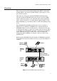
AT-MC601, AT-MC602 Installation and User’s Guide Cabling the Subscriber Unit To cable the Subscriber unit, perform the following steps: 1. First, connect the Ethernet cable from the Ethernet port to the Ethernet port on the computer, as shown in Figure 9. 10Base T/ 100Bas eTX LINK ACT PWR LINE AT-MC 601 VDSL MGMT EXTE NDED ETHE PSTN RNET ERR LINK Figure 9 Ethernet to Computer 2. Then, connect a telephone line cable from the PSTN port to the telephone, as shown in Figure 10.
Installation 3. Next, connect a telephone line cable from the VDSL Line port to the wall/interior telephone line, as shown in Figure 11, so that the Subscriber unit can communicate with the Provider unit.
AT-MC601, AT-MC602 Installation and User’s Guide Installing the AT-MC602 Provider Unit The AT-MC602 Provider unit can be installed in an AT-MCR12 rackmount chassis, used as a desktop device, or mounted onto a wall using the keyholes on the bottom of the unit. The screws and plastic anchors used for mounting the unit are provided. Warning To prevent exposure to electric shock, the AT-MC602 Provider Unit must be installed in a RESTRICTED ACCESS LOCATION and performed by QUALIFIED SERVICE PERSONNEL.
Installation The Provider unit can be mounted onto a wall using the keyholes on the bottom of the unit. The screws and plastic anchors used for mounting the unit are provided. To wall-mount the Provider Unit, perform the following procedure: 1. If attached, remove the protective feet, data cables, and power cord from the unit. 2. Select a wall location for the device. 3. Install the screws and plastic anchors onto the wall, as shown in Figure 7.
AT-MC601, AT-MC602 Installation and User’s Guide Grounding the Provider Unit When an AT-MC602 Provider unit is used as a standalone network extender, you must ground the unit to a ground point to ensure a safe and proper operation.
Installation To install the Provider unit in an AT-MCR12 rackmount chassis, perform the following steps: ERR LINK ACT AT-MC601 LINE MGMT PWR 10BaseT/ 100BaseTX VDSL EXTENDED ETHERNET PSTN LINK 1. Attach the unit to one of the sliders that will hold the unit in the chassis, as shown in Figure 18. Figure 18 Rack Mount - Set on Slider 2. Then, set the slider in the chassis, as shown in Figure 19.
AT-MC601, AT-MC602 Installation and User’s Guide To cable the Provider unit, perform the following steps: 1. First, connect the Ethernet cable from the Ethernet port to the Service Provider box in your wiring closet, as shown in Figure 20. Internet Service Provider ERR LINK ACT AT-MC603 LINE MGMT PWR 10BaseT/ 100BaseTX VDSL EXTENDED ETHERNET PSTN LINK MCR12 Figure 20 Ethernet to Internet Service Provider 2.
Installation 3. Next, connect a telephone line cable from the VDSL Line port to the wall/interior telephone line, as shown in Figure 22, so that the Provider unit can communicate with the Subscriber unit.
AT-MC601, AT-MC602 Installation and User’s Guide Warranty Registration When you have finished installing the network extender, register your product by completing the enclosed warranty card and mailing it to Allied Telesyn.
Chapter 3 Configuration The configuration software allows you to adjust and monitor the operating parameters of the media converter.
AT-MC601, AT-MC602 Installation and User’s Guide Starting a Configuration Session Downloading Software Updates In order to configure and manage your AT-MC601 and AT-MC602 VDSL network extenders, you need to download a copy of the configuration software onto the computers you will use to manage the units. The AT-S57 configuration software is included on the Documentation CD provided with the units. New releases of the AT-S57 configuration software are available from the Allied Telesyn Web site at www.
Configuration Opening the Configuration Software Open the configuration software by double-clicking the “ATS57” application icon, as you would with any other software program. The ATMC60x Configurator pop-up will appear, as shown in Figure 24. Figure 24 AT-MC60x Configurator If you would like to verify that you are using the latest version of the configuration and management software, click the About button on the bottom right of the AT-MC60x Configurator pop-up.
AT-MC601, AT-MC602 Installation and User’s Guide Configuring the Provider Unit After performing the procedure described in the previous section, ”Starting a Configuration Session” on page 36, if you are connected to the Provider unit, the AT- MC60x Configurator menu will appear. The Configurator bar at the top of the menu indicates whether or not the Provider unit has established an Ethernet link by displaying [link DOWN] or [link UP] in brackets.
Configuration The parameters on the Configuration screen are described below. Upstream/Downstream The upstream and downstream data transfer rate. ❑ Actual (Mbps) Displays the actual data transfer rate on the line. The software automatically detects this speed. ❑ Min (Mbps) Allows you to adapt the data transfer rate by setting a minimum speed. ❑ Max (Mbps) Allows you to adapt the data transfer rate by setting a maximum speed. The maximum and minimum speeds in Mbps available in the pull-down menus are: 0.
AT-MC601, AT-MC602 Installation and User’s Guide The Configuration Saved pop-up shown in Figure 27 will appear when the set rate or the highest possible rate has been achieved. Figure 27 Configuration Saved An unsuccessful configuration attempt may include the following status reports: Loading defaults Can’t read link status Done These negative status reports may also be accompanied by error message pop-ups. Error messages are explained in ”Troubleshooting” on page 47.
Configuration VDSL Status To view the VDSL Status screen, click on the VDSL Status tab at the top of the menu. The VDSL Status screen is displayed in Figure 28. Figure 28 VDSL Status The parameters on the VDSL Status screen are described below. These parameters are for viewing and monitoring purposes only. They cannot be changed manually. SNR of Received Signal The Signal-to-Noise Ratio on the VDSL line, measured in decibels. The SNR is a parameter of the constellation of the receive signal.
AT-MC601, AT-MC602 Installation and User’s Guide Reduced Constellation Link A lesser QAM constellation, causing reduced line rates. If the full constellation rate cannot be achieved because the received SNR is too low, then a reduced constellation link can be established and the software can automatically configure the Subscriber unit parameters. TC Synchronized Transmission convergence is synchronized.
Configuration Ethernet Status To view the Ethernet Status screen, click on the Ethernet Status tab at the top of the menu. The Ethernet Status screen is displayed in Figure 29. Figure 29 Ethernet Status The parameters on the Ethernet Status screen are described below. TxRx Counters The data fields in this section indicate the number and type of frames that have been transmitted and received via the Ethernet link.
AT-MC601, AT-MC602 Installation and User’s Guide Stop/Start This button allows you to pause counting. When you press Stop, the counters remain at their present values. When you press Start, the counters continue adding to the values already recorded by the software. Local/Remote Select Local to view the parameters for the Provider unit. Select Remote to view the parameters for the Subscriber unit. The Remote option will only be available when an active link has been established.
Configuration Configuring the Subscriber Unit In rare instances, you may need to use the configuration software on the Subscriber unit to attempt link recovery. If the configuration software detects a problem with the Subscriber unit while you are connected to the Provider unit, it will prompt you to use the software on the Subscriber unit by displaying a pop-up error message.
AT-MC601, AT-MC602 Installation and User’s Guide time, a timeout will occur. After a timeout, the default configuration parameters will be used to establish a link with the highest possible speed. The default configuration parameters start at 0.94 Mbps upstream and downstream with negotiation set from Low -> High. Select the option that corresponds to your mode choice and click the Apply button. When the mode has been set, the AT-MC60x Configurator Done message will appear, as displayed in Figure 31.
Chapter 4 Troubleshooting This chapter contains information on how to troubleshoot the AT-MC601 and AT-MC602 network extenders in the event a problem occurs. Note If after following the instructions in this chapter you are unable to resolve the problem, contact Allied Telesyn Technical Support for assistance. Refer to ”Contacting Allied Telesyn Technical Support” on page 8 for information on how to contact our Technical Support Department. LEDs Check the PWR LED on the front of the network extender.
AT-MC601, AT-MC602 Installation and User’s Guide Verify that the ACT LED for each twisted pair port is ON. If a ACT LED is OFF, do the following: ❑ Verify that the end node connected to the port is powered ON and is operating properly. ❑ Check that the twisted pair cable is securely connected to the port on the network extender and to the port on the end node. ❑ Make sure that the twisted pair cable does not exceed 100 meters (328 feet).
Troubleshooting If you are unable to establish a configuration session with the network extender and receive this error message, check to be sure that the management cable is securely connected to the management port on the network extender and to the RS-232 port on the computer. Then make sure you are selecting the correct COM1 or COM2 port at the software prompt.
AT-MC601, AT-MC602 Installation and User’s Guide ❑ “Configuration file was not found” ❑ “Syntax error in configuration file” ❑ “Configuration cannot be achieved” These last three error messages indicate a problem with the configuration software. Try re-loading the software onto your computer.
Appendix A Default Configuration Settings This appendix lists the AT-MC601 and AT-MC602 default settings. Setting Default Provider Parameters Monitored Speeds Local (Provider) Upstream Max Upstream Min Downstream Max .94 Mbps .94 Mbps .94 Mbps Downstream Min Flow Low to High Ethernet Port Duplex Mode Speed MDI/MDI-X Link Recovery Subscriber Unit Mode .
Appendix B Technical Specifications Physical Specifications Dimensions: (W x D x H) 109 mm x 95 mm x 25 mm (4.29 in. x 3.74 in. x 0.98 in.) Weight: .27 kg (0.6 lbs) Recommended Minimum Clearance on All Sides: 5.08 cm (2.0 in.) Environmental Specifications Operating Temperature: 0° C to 40° C (32° F to 104° F) Storage Temperature: -25° C to 70° C (-13° F to 158° F) Operating Humidity: 5% to 90% (noncondensing) Storage Humidity: 5% to 95% (noncondensing) Operating Altitude: 3,000 m (approx.
Technical Specifications Safety and Electromagnetic Compatibility Certifications Emission: EN55022 ClassA, FCC Part15 ClassA Immunity: EN55024 Safety: EN60950, UL60950, FCC Part68 53
Appendix C Translated Electrical Safety and Emission Information Important: This appendix contains multiple-language translations for the safety statements in this guide. Wichtig: Dieser Anhang enthält Übersetzungen der in diesem Handbuch enthaltenen Sicherheitshinweise in mehreren Sprachen. Vigtigt: Dette tillæg indeholder oversættelser i flere sprog af sikkerhedsadvarslerne i denne håndbog. Belangrijk: Deze appendix bevat vertalingen in meerdere talen van de veiligheidsopmerkingen in deze gids.
Translated Electrical Safety and Emission Information Standards: This product meets the following safety standards. 1 RFI Emission EN55022 Class A, FCC Part 15 Class A 2 Immunity EN55024 3 Electrical Safety EN60950, UL60950, FCC Part 68 Safety 4 Only use the power adapter supplied with the extender. The AT-MC602 can be installed stand alone or can be inserted in the AT-MCR12 chassis. In the last case, the AT-MC602 does not need the power adapter.
AT-MC601, AT-MC602 Installation and User’s Guide Normen: Dieses Produkt erfüllt die Anforderungen der nachfolgenden Normen. 1 Hochfrequenzstörung EN55022 Klasse A, FCC Part 15 Klasse A 2 Störsicherheit EN55024 3 Elektrische Sicherheit EN60950, UL60950, FCC Part 68 Sicherheit 4 Bitte den Adapter nur mit dem mitgelieferten Extender benutzen. Die AT-MC602 kann einzeln benutzt werden oder in der AT-MCR12 Einheit. Im letzteren Fall braucht der AT-MC602 keinen Adapter.
Translated Electrical Safety and Emission Information Standarder: Dette produkt tilfredsstiller de følgende standarder. 1 Radiofrekvens forstyrrelsesemission EN55022 Klasse A, FCC Part 15 Klasse A 2 Immunitet EN55024 3 Elektrisk sikkerhed EN60950, UL60950, FCC Part 68 Sikkerhed 4 Ved installation af converteren må man kun benytte den med købte PSU. AT-MC602 converteren kan installeres som enkelt node eller installeres i et AT-MCR12 chassis.
AT-MC601, AT-MC602 Installation and User’s Guide Eisen: Dit product voldoet aan de volgende eisen. 1 RFI Emissie EN55022 Klasse A, FCC Part 15 Klasse A 2 Immuniteit EN55024 3 Electrische Veiligheid EN60950, UL60950, FCC Part 68 Veiligheid 4 Gebruik alleen de power adapter die meegeleverd is met de verlenger. De AT-MC602 kan als stand alone gebruikt worden, maar kan ook geplaatst worden in de AT-MCR12 chassis. In het laatste geval heeft de AT-MC602 zijn powersupply niet nodig.
Translated Electrical Safety and Emission Information Normes: ce produit est conforme aux normes de suivantes. 1 Eemission d’interférences radioélectriques EN55022 Class A, FCC Part 15 Class A 2 Immunité EN55024 3 Sécurité électrique EN60950, UL60950, FCC Part 68 Sécurité 4 Utiliser uniquement l’adapteur aleatoire fourni avec l’extender. Le AT-MC602 peut etre installe d’une facon autonome, ou insere dans le AT-MCR12 chassis.
AT-MC601, AT-MC602 Installation and User’s Guide Standardit: Tämä tuote on seuraavien standardien mukainen. 1 Radioaaltojen häirintä EN55022 Class A, FCC Part 15 Class A 2 Kestävyys EN55024 3 Sähköturvallisuus EN60950, UL60950, FCC Part 68 Turvallisuus 4 Käytä vain muuntimen mukana toimitettua virtalaitetta. AT-MC602 voidaan käyttää itsenäisesti tai asennettuna AT-MCR12-kehikkoon, jälkimmäisessä tapauksessa AT-MC602 ei tarvitse erillistä virtalaitetta.
Translated Electrical Safety and Emission Information Standard: Questo prodotto è conforme ai seguenti standard. 1 Emissione RFI (interferenza di radiofrequenza) EN55022 Classe A, FCC Part 15 Classe A 2 Immunità EN55024 3 Sicurezza elettrica EN60950, UL60950, FCC Part 68 Norme Di Sicurezza 4 Questo dispositivo deve essere alimentato solo mediante il proprio adattatore. Il dispositivo AT-MC602 puo' essere installato a se' stante o puo' essere inserito nell' unita' AT-MCR12.
AT-MC601, AT-MC602 Installation and User’s Guide Sikkerhetsnormer: Dette produktet tilfredsstiller følgende sikkerhetsnormer. 1 RFI stråling EN55022 Klasse A, FCC Part 15 Klasse A 2 Immunittet EN55024 3 Elektrisk sikkerhet EN60950, UL60950, FCC Part 68 Sikkerhet 4 Ved installation av converteren må man kun benytte den med tilhørende PSU. AT-MC602 converteren kan installeres som enkel node eller installeres i et AT-MCR12 chassis.
Translated Electrical Safety and Emission Information Padrões: Este produto atende aos seguintes padrões. 1 Emissão de interferência de radiofrequência EN55022 Class A, FCC Part 15 Class A 2 Imunidade EN55024 3 Segurança eléctrica EN60950, UL60950, FCC Part 68 Segurança 4 Use apenas adaptador de energia fornecido pelo extensão. O AT-MC602 pode ser instalado de maneira independente ou pode ser colocado dentro da unidade AT-MCR12. No último caso o AT-MC602 não precisa de adaptador de energia.
AT-MC601, AT-MC602 Installation and User’s Guide Estándares: Este producto cumple con los siguientes estándares. 1 Emisión RFI EN55022 Clase A, FCC Part 15 Clase A 2 Inmunidad EN55024 3 Seguridad eléctrica EN60950, UL60950, FCC Part 68 Seguridad 4 Use únicamente el adaptador de corriente suministrado junto con el extensor. El extensor AT-MC602 puede ser instalado en stand alone o puede ser insertado en la unidad AT-MCR12.
Translated Electrical Safety and Emission Information Standarder: Denna produkt uppfyller följande standarder. 1 Radiostörning EN55022 Klass A, FCC Part 15 Klass A 2 Immunitet EN55024 3 Elsäkerhet EN60950, UL60950, FCC Part 68 Säkerhet 4 Använd endast medföljande kraftaggregat till DSL konverteraren. AT-MC602 kan installeras fristående eller monterad i AT-MCR12 enheten. I det senare fallet behöver AT-MC602 inte kraftaggregatet.