AT-RPS9000 & AT-PWR9000 Quick Install Guide
AT-RPS9000 & AT-PWR9000 Quick Install Guide Document Number C613-04040-01 REV C. © 2003-2007 Allied Telesis, Inc. All rights reserved. No part of this publication may be reproduced without prior written permission from Allied Telesis, Inc. Allied Telesis, Inc. reserves the right to change specifications and other information in this document without prior written notice. The information provided herein is subject to change without notice. In no event shall Allied Telesis, Inc.
Quick Install Guide 3 Package Contents The following items are included with each AT-RPS9000: ■ One AT-RPS9000 chassis. ■ One AT-PWR9000 power unit (pre-installed at factory). ■ Two AC power cords. ■ One DC cable for connecting the RPS to an AT-9812T or AT-9816GB switch. ■ One 19 inch rack-mount kit. ■ Two power cord retaining clips. ■ One AT-RPS9000 & AT-PWR9000 Quick Install Guide. ■ One Safety and Statutory Information booklet. ■ One warranty card.
AT-RPS9000 & AT-PWR9000 RPS and Switch Compatibility To provide redundant power to AT-9812T and AT-9816GB switches, use an AT-RPS9000 chassis. The chassis must be fitted with one AT-PWR9000 power unit for each switch that is to receive redundant power. The AT-RPS9000 can take up to four AT-PWR9000 power units, and so can supply up to four switches. AT-PWR9000 power units can only be used in the AT-RPS9000 chassis. Installing the RPS This equipment must be earthed.
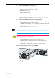
Quick Install Guide 5 5. Place the AT-RPS9000 in its operating location. If installing the RPS on a desktop: • Make sure the RPS’s rubber feet are attached. If installing the RPS in a rack: • Remove the rubber feet. • Attach the rack-mounting brackets. • Mount the RPS in the rack. For more information on selecting a site, see “Selecting a Site” on page 3. 6. Install the AT-PWR9000 power unit (if not already installed).
AT-RPS9000 & AT-PWR9000 7. Connect the DC cable(s) On the AT-RPS9000’s rear panel, attach one end of the provided DC cable to an output connector. Use a connector that is directly behind a bay that has an installed AT-PWR9000 power unit. Figure 2 on page 6 shows the DC output connectors. Attach the other end of the DC cable to the RPS input connector on an AT-9812T or AT-9816GB switch. The RPS input connector is on the switch’s rear panel.
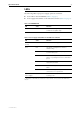
Quick Install Guide 7 LEDs The following LEDs report power supply operations and faults: ■ Power LED on the AT-PWR9000 (Table 1 on page 7) ■ Power supply related LEDs on AT-9800 Series switches (Table 2 on page 7) Table 1: AT-PWR9000 LED LED State Function Power Green The PWR is receiving AC power and the voltage is within an acceptable range Table 2: Power supply related LEDs on AT-9800 Series Switches LED State Function PWR Green The switch is receiving power Red The switch or managemen
AT-RPS9000 & AT-PWR9000 Troubleshooting If the RPS does not function as expected, follow these steps: 1. Check all cable connections are correct and secure. 2. Check that AT-PWR9000 units are installed in the correct bays (bays that have AC input and DC output cables connected). 3. Check the standby switches for the appropriate bays have been pressed, and are in the ON position. 4. Check the RPS is receiving the correct AC voltage. 5.