AT-8700XL SERIES QUICK INSTALL GUIDE
AT-8700XL Series Quick Install Guide Document Number C613-04042-01 REV A. Copyright © 2002 Allied Telesyn International, Corp. 19800 North Creek Parkway, Suite 200, Bothell, WA 98011, USA. All rights reserved. No part of this publication may be reproduced without prior written permission from Allied Telesyn. Allied Telesyn International, Corp. reserves the right to make changes in specifications and other information contained in this document without prior written notice.
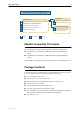
Quick Install Guide 3 Documentation Roadmap Uplink Module AT-8700XL Series Uplink Module Quick Install Guide AT-8700XL Series Safety and Statutory Information Booklet Uplink Module Hardware Reference AT-8700XL Series Quick Install Guide AT-8700XL Series Software Reference General Customer Support AT-8700XL Series Hardware Reference Visit www.alliedtelesyn.com for the latest documentation, FAQs, and support information.
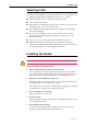
AT-8700XL Series Selecting a Site The switch can be installed in a standard 19-inch rack or on a level surface such as a desktop or bench. When installing the switch, choose a site that: ■ Allows adequate airflow around the switch and its vents. ■ Is free of dust and moisture. ■ Will maintain an ambient temperature range of 0 to 40º C (32 to 104º F) and a humidity range of 5 to 95% non-condensing. ■ Has a reliable and earthed (grounded) power supply circuit, preferably dedicated and filtered.
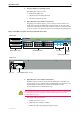
Quick Install Guide 5 6. Place the switch in its operating location If installing the switch in a rack: 7. • Remove the rubber feet. • Attach the rack-mounting brackets. • Mount the switch in the rack. Apply AC power to the switch (for AC models) Plug the power cord into the AC power connector on the switch’s rear panel. The Fault LED should flash for approximately 10 seconds as the switch runs internal tests.
AT-8700XL Series DC power supply specifications: • 48VDC (36-59VDC is acceptable) • Either positive grounded or negative grounded Circuit protection: • Use a 10 Amp circuit breaker To connect the DC supply: a) Ensure that the supply cable is not live b) Strip the supply cable wires to expose 8mm (0.31 in.) of bare conductor c) At the switch, connect the ground wire to the ground terminal (The terminals can be identified by the diagram on the switch’s rear panel, see Figure 2).
Quick Install Guide 7 Configuring the Switch Some configuration is necessary if you wish to enable the switch’s advanced switching capabilities. The switch can be configured via the Command Line Interface (CLI) or Graphical User Interface (GUI). Using the CLI to configure a switch 1. Connect a terminal or PC to the Terminal Port (ASYN0) Using the supplied RS-232 DB9 straight-through cable, connect your terminal or PC to the RS-232 Terminal Port on the switch’s front panel. 2.
AT-8700XL Series To display a list of help topics, enter: help To display help on a specific topic, enter: help topic Alternatively, type a question mark (?) at the end of a partially completed command to see a list of valid options. See the AT-8700XL Series Software Reference for more information on configuring the switch. Using the GUI to configure a switch The GUI requires a PC and web browser. Minimum browser specifications are: Internet Explorer 5.x or Netscape 6.2, with JavaScript enabled.
Quick Install Guide 9 To ensure that configuration settings are saved correctly, use the GUI pages’ menus and buttons to navigate, not your browser’s buttons. As a security precaution, change the password as soon as possible. To change the password, select Management > Users from the sidebar menu. Select the Manager account and click Modify. 7. To access context-sensitive help Click on the Help button [Help] on each page.
AT-8700XL Series Documentation and Tools CD-ROM The Documentation and Tools CD-ROM bundled with each AT-8700XL Series switch contains the complete Documentation Set for your switch and its expansion options, as well as tools for managing the switch. This includes: ■ The AT-8700XL Series Safety booklet, which provides safety and statutory information for the AT-8700XL Series switch and its expansion options.