
User Manual


Table Of Contents
- Contents
- Figures
- Preface
- Section I
- Basic Operations
- Chapter 1
- Starting a Web Browser Management Session
- Chapter 2
- Basic Switch Parameters
- Chapter 3
- Enhanced Stacking
- Chapter 4
- SNMPv1 and SNMPv2c Community Strings
- Chapter 5
- Port Parameters
- Chapter 6
- MAC Address Table
- Chapter 7
- Static Port Trunks
- Chapter 8
- Port Mirroring
- Section II
- Advanced Operations
- Chapter 9
- File System
- Chapter 10
- File Downloads and Uploads
- Chapter 11
- Event Log and Syslog Servers
- Chapter 12
- Classifiers
- Chapter 13
- Access Control Lists
- Chapter 14
- Quality of Service
- Chapter 15
- Class of Service
- Chapter 16
- IGMP Snooping
- Chapter 17
- Denial of Service Defense
- Chapter 18
- Power Over Ethernet
- Section III
- SNMPv3 Operations
- Chapter 19
- SNMPv3
- Enabling the SNMP Protocol
- Configuring the SNMPv3 User Table
- Configuring the SNMPv3 View Table
- Configuring the SNMPv3 Access Table
- Configuring the SNMPv3 SecurityToGroup Table
- Configuring the SNMPv3 Notify Table
- Configuring the SNMPv3 Target Address Table
- Configuring the SNMPv3 Target Parameters Table
- Configuring the SNMPv3 Community Table
- Displaying SNMPv3 Tables
- Section IV
- Spanning Tree Protocols
- Chapter 20
- Spanning Tree, Rapid Spanning Tree, and Multiple Spanning Tree Protocols
- Section V
- Virtual LANs
- Chapter 21
- Port-based and Tagged Virtual LANs
- Chapter 22
- GARP VLAN Registration Protocol
- Chapter 23
- Protected Ports VLANs
- Section VI
- Port Security
- Chapter 24
- MAC Address-based Port Security
- Chapter 25
- 802.1x Port-based Network Access Control
- Section VII
- Management Security
- Chapter 26
- Encryption Keys, PKI, and SSL
- Chapter 27
- Secure Shell Protocol
- Chapter 28
- TACACS+ and RADIUS Authentication Protocols
- Chapter 29
- Management Access Control List
- Index
AT-S62 Management Sofwatre Web Browser Interface User’s Guide
Section II: Advanced Operations 113
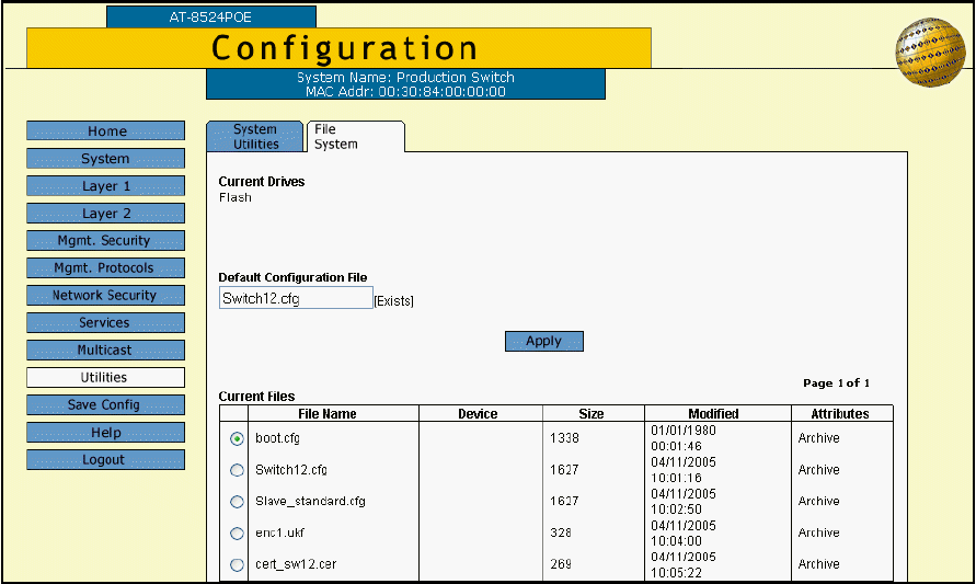
The File System tab is shown in Figure 27.
Figure 27. File System Tab
The information in the tab is defined below:
Current Drive
Specifies the location of the file system. The AT-8500 Series switch
has just one file system, located in flash memory. This will always
indicate Flash. This cannot be changed.
Default Configuration File
Specifies the filename of the active configuration file. The switch uses
this file to configure its operating parameters when it is reset or power
cycled. The active boot file is also the file that is updated when you
select the Save Config option.
Current Files
Lists the files stored in the file system. The columns are defined here:
File Name - The name of the system file.
Device - The storage location of the file. This column will be empty for
all files on an AT-8500 Series switch.
Size - The size of the file in kilobytes.
Modified - The date the file was created or last modified.