
User guide

AT-S63 Management Software Command Line User’s Guide
Section I: Basic Operations 107
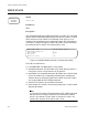
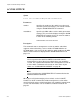
Figure 32 is an example of the command from the master switch of a
functioning stack. The switches in the stack and their module ID numbers
are displayed in a table.
Figure 32. SHOW STACK Command of a Stack
The fields and columns are defined here:
Local MAC Addr - The MAC address of the master switch of the stack.
The local and master MAC addresses will always be the same.
Master MAC Addr - The MAC address of the master switch of the
stack.
Backup Master MAC Addr - The MAC address of the backup master
switch of the stack. A stack will have a backup master if the switches
have static ID numbers. A stack with dynamic module ID numbers will
not have a backup master.
Topology - The cabling topology of the stack. Possible values are
Duplex_Chain and Duplex_Ring.
My ModuleID - The module ID number of the master switch of the
stack. The master switch always has the ID number 1.
ModuleID Assignment Mode - The assignment method of the ID
numbers of the switches. If AUTOMATIC, the switches were assigned
dynamic ID numbers. If STATIC, the switches were assigned static ID
numbers.
Current State - The current state of the master switch. This will always
be Master.
Module Count - The number of switches in the stack.
Module - The module ID number of a switch.
Stack State - The state of a switch. A switch will be either Master or
Member.
Model Name - The Allied Telesis model name of a switch.
Local MAC Addr :00:30:84:00:00:02
Master MAC Addr :00:30:84:00:00:02
Backup Master MAC Addr :00:30:84:00:00:54
Topology :Duplex_Chain
My ModuleID :1
ModuleID Assignment Mode :STATIC
Current State :Master
Module Count :4
--------------------------------------------------------------
Module | Stack State | Model Name | Priority | Mac Address
1 | Master | AT-9424Ts/XP | 16 | 00:30:84:00:00:02
2 | Member | AT-9424Ts/XP | 16 | 00:30:84:00:00:52
3 | Member | AT-9424Ts/XP | 16 | 00:30:84:00:00:22
4 | Member | AT-9424Ts/XP | 16 | 00:30:84:00:00:82