
User Manual

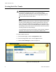


Table Of Contents
- Contents
- Figures
- Tables
- Preface
- Section I
- Basic Operations
- Chapter 1
- Basic Switch Parameters
- Chapter 2
- Port Parameters
- Chapter 3
- SNMPv1 and SNMPv2c
- Chapter 4
- MAC Address Table
- Chapter 5
- Static Port Trunks
- Chapter 6
- Port Mirroring
- Section II
- Advanced Operations
- Chapter 7
- File System
- Chapter 8
- File Downloads and Uploads
- Chapter 9
- Event Logs and the Syslog Client
- Chapter 10
- IGMP Snooping
- Section III
- SNMPv3
- Chapter 11
- SNMPv3
- Configuring the SNMPv3 Protocol
- Enabling or Disabling SNMP Management
- Configuring the SNMPv3 User Table
- Configuring the SNMPv3 View Table
- Configuring the SNMPv3 Access Table
- Configuring the SNMPv3 SecurityToGroup Table
- Configuring the SNMPv3 Notify Table
- Configuring the SNMPv3 Target Address Table
- Configuring the SNMPv3 Target Parameters Table
- Configuring the SNMPv3 Community Table
- Displaying the SNMPv3 Tables
- Displaying the User Table Entries
- Displaying the View Table Entries
- Displaying the Access Table Entries
- Displaying the SecurityToGroup Table Entries
- Displaying the Notify Table Entries
- Displaying the Target Address Table Entries
- Displaying the Target Parameters Table Entries
- Displaying the SNMPv3 Community Table Entries
- Section IV
- Spanning Tree Protocols
- Chapter 12
- Spanning Tree and Rapid Spanning Tree Protocols
- Section V
- Virtual LANs
- Chapter 13
- Port-based and Tagged VLANs
- Section VI
- Port Security
- Chapter 14
- 802.1x Port-based Network Access Control
- Index

Chapter 5: Static Port Trunks
74 Section I: Basic Operations
Note
Although a static port trunk can consist of ports from different
switches in a stack, you can only choose ports from one switch
during the initial configuration. Afterwards, you can add more ports
to it from other switches in the stack.
5. Use the pull-down Stack ID menu in the upper left corner of the switch
image to select one of the switches in the stack with ports that you
want to be members of the port trunk and click the Apply button. If the
switch is already displayed, you can skip this step.
6. In the switch image, click the ports of the trunk. A selected port turns
white. To deselect a port, click it again.
7. Click the Trunk Name field and enter a name of up to 16 alphanumeric
characters for the trunk. Spaces or special characters, such as
asterisks and exclamation points, are not permitted. Each trunk must
have a unique name.
8. From the Trunk Method pull-down menu, select the load distribution
method for the trunk. The possible settings are:
SA - Source MAC address (Layer 2)
DA - Destination MAC address (Layer 2)
SA/DA - Source MAC address /destination MAC address (Layer 2)
SI - Source IP address (Layer 3)
DI - Destination IP address (Layer 3)
SI/DI - Source IP address /destination IP address (Layer 3)
9. Click the Apply button to create the new trunk.
10. To save your changes in the master configuration file, click the Save
Config button in the Configuration menu.
11. To add more ports to the trunk from other switches in the stack, refer
to “Modifying Static Port Trunks” on page 75.
12. Configure the ports on the remote device for port trunking.
13. Connect the cables to the ports of the trunk on the switch and on the
remote device.
The port trunk is ready for network operations.