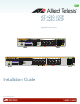
AT-x230-10GP AT-x230-18GP Gigabit Ethernet Switches x230-10GP 1 3 5 7 SFP 9 CONSOLE MAC Address Label SD FAULT SD 10 POWER 2 RS-232 1000 LINK MAC Address Label Installation Guide C613-04068-00 REV A ACT 10/100 LINK 4 ACT 6 8 PD ON PD ERR MAX CURRENT
Copyright 2014 Allied Telesis, Inc. All rights reserved. No part of this publication may be reproduced without prior written permission from Allied Telesis, Inc. Allied Telesis and the Allied Telesis logo are trademarks of Allied Telesis, Incorporated. All other product names, company names, logos or other designations mentioned herein are trademarks or registered trademarks of their respective owners. Allied Telesis, Inc.
Electrical Safety and Emissions Standards This product meets the following standards. U.S. Federal Communications Commission Radiated Energy Note: This equipment has been tested and found to comply with the limits for a Class A digital device pursuant to Part 15 of FCC Rules. These limits are designed to provide reasonable protection against harmful interference when the equipment is operated in a commercial environment.
Translated Safety Statements Important: The indicates that a translation of the safety statement is available in a PDF document titled Translated Safety Statements posted on the Allied Telesis website at www.alliedtelesis.com.
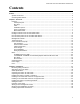
AT-x230-10GP and AT-x230-18GP Switches Installation Guide Contents Preface............................................................................................................................................................... 1 Symbol conventions ..................................................................................................................................... 2 Contacting Allied Telesis...............................................................................................
Contents Chapter 3: Troubleshooting........................................................................................................................... 63 Appendix A: Technical Specifications.......................................................................................................... 67 Physical specifications................................................................................................................................ 67 Dimensions ..................................
Figures Figure 1: AT-x230-10GP packaging ...................................................................................................................................... 8 Figure 2: AT-x230-18GP packaging ...................................................................................................................................... 9 Figure 3: AT-x230-10GP front panel.................................................................................................................................
List of Figures vi
Tables Table 1. IEEE powered device classes ..............................................................................................................................17 Table 2. Twisted pair cable requirements for the 10BASE-T and 100BASE-TX ports at 10 or 100Mbps ..........................18 Table 3. Twisted pair cable requirements for the 10/1000BASE-T and 100BASE-TX ports at 1000Mbps ........................19 Table 4. AT-x230-10GP and AT-x230-18GP POWER LED functional descriptions .................
List of Tables viii
AT-x230-10GP and AT-x230-18GP Switches Installation Guide Preface This guide contains the installation instructions for the AT-x230-10GP and AT-x230-18GP Gigabit Ethernet Switches.
Symbol conventions This document uses the following conventions: Note Notes provide additional information. Caution Cautions inform you that performing or omitting a specific action may result in equipment damage or loss of data. Warning Warnings inform you that performing or omitting a specific action may result in bodily injury. Warning Warnings inform you that an eye and skin hazard exists due to the presence of a Class 1 laser device.
AT-x230-10GP and AT-x230-18GP Switches Installation Guide Contacting Allied Telesis If you need assistance with this product, you may contact Allied Telesis technical support by going to the Support & Services section of the Allied Telesis web site at www.alliedtelesis.com/support.
4
AT-x230-10GP and AT-x230-18GP Switches Installation Guide Chapter 1 Overview This chapter provides descriptions of the AT-x230-10GP and AT-x23018GP Gigabit Ethernet Switches and contains the following sections: “Features” on page 6 “Package contents for the AT-x230-10GP Switch” on page 8 “Package contents for the AT-x230-18GP Switch” on page 9 “Front and back panels on the AT-x230-10GP Switch” on page 10 “Front and back panels on the AT-x230-18GP Switch” on page 12 “Management softw
Chapter 1: Overview Features This section describes the hardware features of the AT-x230-10GP and AT-x230-18GP Gigabit Ethernet Switches. Twisted pair ports SFP slots Here are the basic features of the 10/100/1000Mbps twisted-pair ports: 8 or 16 PoE ports per switch 10BASE-T (IEEE 802.3i), 100BASE-TX (IEEE 802.3u) and 1000BASE-T (IEEE 802.3ab) compliant IEEE 802.3u Auto-Negotiation compliant Auto-MDI/MDIX PoE Plus Full wire-speed non-blocking IEEE 802.
AT-x230-10GP and AT-x230-18GP Switches Installation Guide LEDs Here is a brief description of the port LEDs: POWER and FAULT LEDs; refer to “POWER and FAULT LEDs” on page 22. Link/Activity/Speed/PoE LEDs for the twisted pair ports; see “10/ 1000BASE-T/100BASE-TX Link/Activity/Speed LED and PoE status LED” on page 24. Link/Activity LEDs for the SFP slots; see “SFP LEDs” on page 27. SD card LED: refer to “SD card LED” on page 28.
Chapter 1: Overview Package contents for the AT-x230-10GP Switch Figure 1 illustrates the package contents for the AT-x230-10GP Gigabit Ethernet Switch. FIGURE 1. AT-X230-10GP PACKAGING x2 30 -10 GP MA CA dd ress SD Lab el CO NSO LE 1 RS23 3 SD FA 2 ULT PO WER 1000 5 7 LINK AC T 10/1 2 00 LINK SF 4 AC T P 6 9 PD 8 ON PD ER R MAX CU 10 RR EN T AT-x230-10GP 1 Power cable hook 8 1 Power cable (1.
AT-x230-10GP and AT-x230-18GP Switches Installation Guide Package contents for the AT-x230-18GP Switch Figure 2 illustrates the package contents for the AT-x230-18GP Gigabit Ethernet Switch. FIGURE 2. AT-X230-18GP PACKAGING AT-x230-18GP 1 Power cable hook 1 Power cable (1.
Chapter 1: Overview Front and back panels on the AT-x230-10GP Switch Figure 3 illustrates the front panel of the AT-x230-10GP Gigabit Ethernet Switch. FIGURE 3.
AT-x230-10GP and AT-x230-18GP Switches Installation Guide Figure 4 illustrates the back panel of the AT-x230-10GP Gigabit Ethernet Switch. FIGURE 4.
Chapter 1: Overview Front and back panels on the AT-x230-18GP Switch Figure 5 illustrates the front panel of the AT-x230-18GPGigabit Ethernet Switch. FIGURE 5.
AT-x230-10GP and AT-x230-18GP Switches Installation Guide Figure 6 illustrates the back panel of the AT-x230-18GP Gigabit Ethernet Switch. FIGURE 6.
Chapter 1: Overview Management software The switches are shipped with the management software pre-installed. The software provides a command line interface and a GUI (Graphical User Interface) for in-band, over-the-network management.
AT-x230-10GP and AT-x230-18GP Switches Installation Guide Twisted pair ports The AT-x230-10GP and AT-x230-18GP Gigabit Ethernet Switches feature 8 and 16 twisted pair ports, respectively. All ports are 10BASE-T, 100BASE-TX, and 1000BASE-T compliant. You can set the port speeds and duplex modes either automatically with IEEE 802.3u Auto-Negotiation or manually with the management software. The twisted pair ports feature 8-pin RJ45 connectors.
Chapter 1: Overview Power over Ethernet (PoE) The AT-x230-10GP and AT-x230-18GP switches feature Power over Ethernet (PoE) on the 10/1000BASE-T and 100BASE-TX ports. PoE is used to supply power to network devices over the same twisted pair cables that carry the network traffic. The main advantage of PoE is that it can make it easier to install a network. The selection of a location for a network device is often limited by whether there is a power source nearby.
AT-x230-10GP and AT-x230-18GP Switches Installation Guide TABLE 1. IEEE POWERED DEVICE CLASSES Class Maximum power output from a switch port PD power range Margin of cable loss 0 16.2W 0.44W to 12.95W 0.8W 1 4.2W 0.44W to 3.84W 0.2W 2 7.4W 3.84W to 6.49W 0.4W 3 16.2W 6.49W to 12.95W 0.8W 4 31.2W 12.95W to 25.5W 1.2W Cable requirements The cable requirements for ports operating at 10 or 100Mbps are given in Table 2.
Chapter 1: Overview TABLE 2.
AT-x230-10GP and AT-x230-18GP Switches Installation Guide TABLE 3.
Chapter 1: Overview number of PoE devices so that all of the devices receive power. Otherwise, the switch powers a subset of the devices, based on port prioritization. The switch can handle different power requirements on different ports. This enables you to connect different classes of PoE equipment to the ports on the switch.
AT-x230-10GP and AT-x230-18GP Switches Installation Guide Wiring implementation The IEEE 802.3af standard defines two methods for the delivery of DC power over twisted pair cable by a PSE, such as the switch, to PDs. These methods, known as modes A and B, identify the wires within the cable that carry the DC power from the PSE to a PD. Twisted pair cabling typically consists of eight wires.
Chapter 1: Overview LEDs This section describes the four types of LEDs on the x230 Series Switches: POWER and FAULT LEDs “POWER and FAULT LEDs” on page 22 “10/1000BASE-T/100BASE-TX Link/Activity/Speed LED and PoE status LED” on page 24 “SFP LEDs” on page 27 “SD card LED” on page 28 The POWER LED reports the status of AC power and is located on the front panel of the of the switches beside the console port. See Figure 7.
AT-x230-10GP and AT-x230-18GP Switches Installation Guide Table 4 describes the POWER LED for the AT-x230-10GP and AT-x23018GP switches. TABLE 4. AT-X230-10GP AND AT-X230-18GP POWER LED FUNCTIONAL DESCRIPTIONS LED Description State Off Indicates either the switch is not receiving AC power or the AC input power is operating outside the normal range Steady green The switch is receiving AC input power and is operating normally POWER Figure 8 shows the location of the FAULT LED. FIGURE 8.
Chapter 1: Overview Table 5 describes the functions of the FAULT LED for the AT-x230-10GP and AT-x230-18GP switches. TABLE 5.
AT-x230-10GP and AT-x230-18GP Switches Installation Guide FIGURE 9. AT-X230-10GP LINK/ACTIVITY/SPEED AND POE LEDS PoE status LED Link/activity/speed LED 10/100/1000Mbps PoE+ ports 1 3 5 7 LT WER 2 ACT 10/100 LINK 4 ACT 6 8 PD ON PD ERR MAX C FIGURE 10.
Chapter 1: Overview Table 6 describes the AT-x230-10GP and AT-x230-18GP Link/Activity/ Speed and PoE status LEDs. TABLE 6. AT-X230-10GP AND AT-X230-18GP LINK/ACTIVITY/SPEED AND POE LED DESCRIPTIONS LED Link/Activity/ Speed (LEFT LED) State Description Off The port has not established a link with a network device, or the ecofriendly feature is enabled.
AT-x230-10GP and AT-x230-18GP Switches Installation Guide SFP LEDs The AT-x230-10GP and AT-x230-18GP switches have SFP Link/Activity LEDs on the front panel. See Figure 11. The SFP Link/Activity LEDs indicate the activity status for each SFP slot. Each SFP slot has ONE uni-color LED: The LEFT LED corresponds to the UPPER SFP port The RIGHT LED corresponds to the LOWER SFP port Note All of the port LEDs are OFF when the switch is operating in the low power mode.
Chapter 1: Overview Table 7 describes the functions of the SFP Link/Activity LEDs TABLE 7.
AT-x230-10GP and AT-x230-18GP Switches Installation Guide The SD card LED indicates whether the SD card slot has a card inserted, or is reading or writing. Table 8 describes the functions of the SD card LED. TABLE 8.
Chapter 1: Overview ecofriendly button By pressing the ecofriendly button you can conserve energy. When you press the ecofriendly button for 1 to 4 seconds, the front panel port LEDs are disabled. You may use the button to turn off the LEDs when you are not monitoring the switch. To turn the port LEDs on, press the ecofriendly button for 1 to 4 seconds again. Toggling the LEDs does not affect the network operations of the switch. FIGURE 13.
AT-x230-10GP and AT-x230-18GP Switches Installation Guide Power supply Each switch has an internal power supply with a single AC power supply socket on the back panel. To power the switch on or off, connect or disconnect the power cord provided with the switch. A power cord and a power cord retainer hook are supplied with the switch. For the power requirements, see “Power specifications” on page 68.
Chapter 1: Overview Fans Both the AT-x230-10GP and AT-x230-18GP switches have one and two internal fans respectively. You cannot remove or replace these fans in the field. The fan status is indicated with the FAULT LED. See “POWER and FAULT LEDs” on page 22 and Table 5 on page 24 for more information.
AT-x230-10GP and AT-x230-18GP Switches Installation Guide Chapter 2 Installation This chapter contains the following sections: “Reviewing safety precautions” on page 34 “Selecting a site for the switch” on page 36 “Cable specifications” on page 37 “Unpacking the switch: AT-x230-10GP” on page 38 “Unpacking the switch: AT-x230-18GP” on page 39 “Installing the switch on a table or a desktop” on page 40 “Installing an AT-x230-10GP switch in an equipment rack” on page 42 “Install
Chapter 2: Installation Reviewing safety precautions Please review the following safety precautions before you begin to install the chassis or any of its components. Note The indicates that a translation of the safety statement is available in a PDF document titled Translated Safety Statements. Warning To prevent electric shock, do not remove the cover. No userserviceable parts inside. This unit contains hazardous voltages and should only be opened by a trained and qualified technician.
AT-x230-10GP and AT-x230-18GP Switches Installation Guide All countries: Install product in accordance with local and National Electrical Codes. E8 Circuit overloading: Consideration should be given to the connection of the equipment to the supply circuit and the effect that overloading of circuits might have on overcurrent protection and supply wiring. Appropriate consideration of equipment nameplate ratings should be used when addressing this concern.
Chapter 2: Installation Selecting a site for the switch Observe the following requirements when choosing a site for your switch: 36 If you plan to install the switch in an equipment rack, verify that the rack is safely secured and will not tip over. Devices in a rack should be installed starting at the bottom, with the heavier devices near the bottom of the rack. If you are installing the switch on a table, verify that the table is level and secure.
AT-x230-10GP and AT-x230-18GP Switches Installation Guide Cable specifications Table 9 contains the cable specifications for the twisted pair ports. TABLE 9. TWISTED PAIR CABLING AND DISTANCES Speed Type of cable Maximum operating distance 10 Mbps Standard TIA/EIA 568-B-compliant Category 3 or better shielded or unshielded cabling with 100 ohm impedance and a frequency of 16 MHz.
Chapter 2: Installation Unpacking the switch: AT-x230-10GP To unpack the switch, perform the following procedure: 1. Remove all of the components from the shipping package. Note Store the packaging material in a safe location. You must use the original shipping material if you need to return the unit to Allied Telesis. 2. Place the switch on a level, secure surface. 3.
AT-x230-10GP and AT-x230-18GP Switches Installation Guide Unpacking the switch: AT-x230-18GP To unpack the switch, perform the following procedure: 1. Remove all of the components from the shipping package. Note Store the packaging material in a safe location. You must use the original shipping material if you need to return the unit to Allied Telesis. 2. Place the switch on a level, secure surface. 3.
Chapter 2: Installation Installing the switch on a table or a desktop You can install AT-x230-10GP and AT-x230-18GP switches on a desktop, in a standard 19-inch equipment rack, or on a wall. To install an AT-x230-10GP switch in a rack, see “Installing an AT-x23010GP switch in an equipment rack” on page 42. To install an AT-x230-18GP switch in a rack, see “Installing an AT-x23018GP switch in an equipment rack” on page 45.
AT-x230-10GP and AT-x230-18GP Switches Installation Guide FIGURE 14. ATTACHING THE RUBBER FEET TO A SWITCH 1000 LINK RS-232 ACT 10/100 LINK 2 ACT PD ON 4 6 PD ERR MAX CURRENT 8 POWER SD 10 FAULT MAC Address Label SD CONSOLE 9 x230-10GP 1 3 5 7 SFP 4. Turn the switch over again and place it on a flat, secure surface (such as a desk or table) leaving ample space around the unit for ventilation. 5. Go to “Cabling the switch” on page 50.
Chapter 2: Installation Installing an AT-x230-10GP switch in an equipment rack These instructions show you how to install an AT-x230-10GP switch in an equipment rack. Rack mount kits for the AT-x230-10GP switch, ATRKMT-J14, can be purchased separately from your Allied Telesis dealer. To install an AT-x230-10GP switch in a 19-inch equipment rack, follow these steps: 1. If rubber feet are attached to the base of the switch, place the unit upside down on a level, secure surface. 2.
AT-x230-10GP and AT-x230-18GP Switches Installation Guide 4. Attach two rack mount brackets to the sides of the switch using the eight bracket screws that come with the rack mount kit AT-RKMT-J14 (Figure 16). FIGURE 16.
Chapter 2: Installation 5. Mount the AT-x230-10GP switch in a 19-inch equipment rack using four equipment rack screws (supplied with the equipment rack) (Figure 17). FIGURE 17. MOUNTING AN AT-X230-10GP SWITCH IN AN EQUIPMENT RACK x2 30 -10 GP MA CA dd re ss SD Lab el CO NSO LE 1 3 SD RS- 23 2 FA ULT PO WER 1000 5 7 LINK AC T 10/1 2 00 LINK AC SFP 4 T 6 9 PD 8 ON PD ER R MAX CU 10 RR EN T 6.
AT-x230-10GP and AT-x230-18GP Switches Installation Guide Installing an AT-x230-18GP switch in an equipment rack These instructions show you how to install an AT-x230-18GP switch in an equipment rack. Rack mount kits for the AT-x230-18GP switch, AT-RKMTJ13, can be purchased separately from your Allied Telesis dealer. To install an AT-x230-18GP switch in a 19-inch equipment rack, follow these steps: 1.
Chapter 2: Installation 4. Attach two rack mount brackets to the sides of the switch using the six bracket screws that come with the rack mount kit AT-RKMT-J13 (Figure 19). FIGURE 19.
AT-x230-10GP and AT-x230-18GP Switches Installation Guide 5. Mount the AT-x230-18GP switch in a 19-inch equipment rack using four equipment rack screws (supplied with the equipment rack) (Figure 20). FIGURE 20. MOUNTING AN AT-X230-18GP SWITCH IN AN EQUIPMENT RACK 6.
Chapter 2: Installation Installing the switch on a wall using brackets These instructions show you how to install an AT-x230-10GP or AT-x23018GP switch on a wall. Wall mount kits can be purchased separately from your Allied Telesis dealer. Note In the following illustrations, only the AT-x230-10GP switch is shown. To install the switch on a wall, perform the following procedure: 1. Turn the switch over and place it on a table. 2.
AT-x230-10GP and AT-x230-18GP Switches Installation Guide 4. While another person holds the switch at the wall location, secure it to the wall using the eight wall mounting screws. See Figure 22. POWER 1000 LINK FAULT SD MAC Address Label x230-10GP CONSOLE RS-232 SD 1 ACT 3 10/100 LINK ACT 5 7 PD ON PD ERR MAX CURRENT FIGURE 22. SECURING THE SWITCH TO THE WALL 5. Go to “Cabling the switch” on page 50.
Chapter 2: Installation Cabling the switch Observe the following guidelines when connecting twisted pair and fiber optic cables to the ports on the switch: 50 The connector on the cable should fit snugly into the port on the switch. The tab on the connector should lock the connector into place. Because the twisted pair ports have auto-MDI/MDIX, you may use straight-through twisted pair cable to connect any type of network device to the switch.
AT-x230-10GP and AT-x230-18GP Switches Installation Guide The default speed setting for the ports is Auto-Negotiation. This setting is appropriate for ports connected to network devices that also support Auto-Negotiation. The default speed setting of Auto-Negotiation is not appropriate for ports connected to 10BASE-T and 100BASE-TX network devices that do not support Auto-Negotiation and have fixed speeds.
Chapter 2: Installation Powering on the switch To power on the AT-x230-10GP or AT-x230-18GP switch, perform the following procedure: 1. Lift the power cable hook, as shown in Figure 23, on the back of the switch. FIGURE 23. LIFTING THE AC POWER CABLE HOOK ON AN X230 SERIES SWITCH Power cable hook Power cable hook mount 2. Plug the power cord into the AC power connector, as shown in Figure 24, on the back of an AT-x230-10GP or AT-x230-18GP switch. FIGURE 24.
AT-x230-10GP and AT-x230-18GP Switches Installation Guide 3. Plug the other end of the power cord into a wall outlet. Warning Power cord is used as a disconnection device. To de-energize equipment, disconnect the power cord. E3 Pluggable Equipment: The socket outlet shall be installed near the equipment and shall be easily accessible. E5 4. Verify that the POWER LED is green. If the LED is OFF, see Chapter 3, “Troubleshooting” on page 63. The switch is now powered on and ready for network operations.
Chapter 2: Installation Starting a local management session This procedure requires a terminal or a terminal emulator program and the management cable that comes with the switch. To start a local management session on the switch, perform the following procedure: 1. Connect the RJ45 connector on the management cable to the console port on the front panel of the switch, as shown below. FIGURE 25.
AT-x230-10GP and AT-x230-18GP Switches Installation Guide Note The port settings are for a DEC VT100 or ANSI terminal, or an equivalent terminal emulator program. 4. If you have not already done so, power up the switch as described in the previous steps.
Chapter 2: Installation Monitoring the initialization processes It takes about thirty seconds for the switch to initialize its management software programs and features, and load the default configuration. You may also monitor the bootup sequence by connecting a terminal or computer that has a terminal emulator program, to the console port on the master switch. You will see the messages from Figure 26 below to Figure 28 on page 58. FIGURE 26. SWITCH INITIALIZATION MESSAGES Verifying release... OK Booting..
AT-x230-10GP and AT-x230-18GP Switches Installation Guide FIGURE 27. SWITCH INITIALIZATION MESSAGES (CONTINUED) Starting base/portmapper... [ OK ] Starting base/reboot-stability... [ OK ] Checking system reboot stability... [ OK ] Starting base/cron... [ OK ] Starting base/appmond... [ OK ] Starting hardware/openhpi... [ OK ] Starting hardware/timeout... [ OK ] Starting base/inet... [ OK ] Starting base/modules... [ OK ] [ OK ] Starting network/startup...
Chapter 2: Installation FIGURE 28. SWITCH INITIALIZATION MESSAGES (CONTINUED) Received event network.
AT-x230-10GP and AT-x230-18GP Switches Installation Guide Installing optional SFP transceivers To install an SFP transceiver, perform the following procedure: Note The transceiver can be hot-swapped; you do not need to power off the switch to install a transceiver. However, always remove the cables before removing the transceiver. Note You should always install the transceiver before connecting the fiber optic cables to it. 1.
Chapter 2: Installation 3. Position the SFP transceiver with the label facing up. 4. Gently slide the transceiver into the SFP slot until it clicks into place as shown in Figure 30. FIGURE 30. INSERTING AN SFP TRANSCEIVER INTO AN SFP SLOT SFP 5. Verify that the handle on the transceiver is in the upright position, as shown in Figure 31. This secures the transceiver and prevents it from being dislodged from the slot. FIGURE 31.
AT-x230-10GP and AT-x230-18GP Switches Installation Guide 6. Eject SFP transceivers, as shown in Figure 32. First lower the SFP transceiver handle, then gently remove the SFP transceiver. FIGURE 32. EJECTING AN SFP TRANSCEIVER AFTER LOWERING THE SFP HANDLE TO THE DOWNWARDS POSITION SFP 7. Repeat steps 2 through 6 to install an additional SFP transceiver. Note SFP transceivers are dust sensitive. Always keep the plug in the optical bores when a fiber optic cable is not installed, or when storing the SFP.
Chapter 2: Installation 62
AT-x230-10GP and AT-x230-18GP Switches Installation Guide Chapter 3 Troubleshooting This chapter contains information on how to troubleshoot the switch if a problem occurs. Note For further assistance, please contact Allied Telesis Technical Support at www.alliedtelesis.com/support. Problem 1: The POWER LED on the front of the switch is off. Solutions: The unit is not receiving power.
Chapter 3: Troubleshooting Try connecting another network device to the twisted pair port with a different cable. If the twisted pair port is able to establish a link, then the problem is with the cable or the other network device. Verify that the twisted pair cable does not exceed 100 meters (328 feet). Verify that you are using the appropriate category of twisted pair cable: Category 3 or better for 10 Mbps operation and Category 5 and Category 5E for 100 and 1000 Mbps operation.
AT-x230-10GP and AT-x230-18GP Switches Installation Guide Problem 5: Network performance between a twisted pair port on the switch and a network device is slow. Solution: There might be a duplex mode mismatch between the port and the network device. This occurs when a twisted pair port using AutoNegotiation is connected to a device with a fixed duplex mode of full duplex.
Chapter 3: Troubleshooting 66
AT-x230-10GP and AT-x230-18GP Switches Installation Guide Appendix A Technical specifications This appendix describes the technical specifications of the AT-x230-10GP and AT-x230-18GP switches. Physical specifications Dimensions TABLE 10. CHASSIS DIMENSIONS Model W x D x H mm (in) AT-x230-10GP 210 mm x 275mm x 42.5 mm (8.27 in x 10.83 in x 1.67 in) AT-x230-18GP 341 mm x 231mm x 44mm (13.42 in x 9.10 in x 1.73 in) Weight TABLE 11. CHASSIS WEIGHT Model Weight AT-x230-10GP 2.1 kg (4.
Appendix A: Technical specifications Power specifications Input supply voltage - 100-240 VAC, 50 - 60 Hz, 2.4A maximum TABLE 13. CHASSIS WEIGHT Model Power budget Maximum power consumption AT-x230-10GP 123 W 180 W AT-x230-18GP 247 W 247 W Electrical safety and electromagnetic certifications TABLE 14.
AT-x230-10GP and AT-x230-18GP Switches Installation Guide Connectors and port pinouts This section lists the connectors and connector pinouts. Figure 33 illustrates the pin layout for an RJ45 connector and port. FIGURE 33. RJ45 CONNECTOR AND PORT PIN LAYOUT Table 15 lists the RJ45 pin signals when a twisted pair port is operating in the MDI configuration. TABLE 15.
Appendix A: Technical specifications Table 17 lists the RJ45 connector pins and their signals when a 1000BASE-T port is operating at 1000Mbps. TABLE 17.