
User's Manual
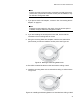
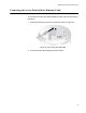
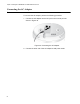
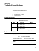
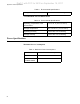
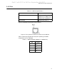
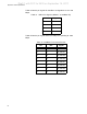
Table Of Contents
- Contents
- Preface
- Chapter 1
- Chapter 2
- Installing the AT-MWS2533AP Access Point
- Reviewing Safety Precautions
- Unpacking the AT-MWS2533AP Access Point
- Unpacking the AT-BRKT-MWS01 Mounting Base Plate
- Unpacking the AT-MWS0091 AC Adapter Kit
- Installing the Access Point on a Celling or Wall
- Connecting the Access Point with the Ethernet Cable
- Connecting the AC Adapter
- Assembling the AT-MWS0091 AC Adapter
- Installing the AT-MWS2533AP Access Point
- Chapter 3
- Appendix A

MWS Series Access Point Installation Guide
57
LAN Port
Figure 31 illustrates the pin layout of the LAN port.
Figure 31. Pin Layout for the RJ45 Connector on the LAN Port
Table 13 lists the pin signals when the port is operating in the MDI
configuration at 10 or 100 Mbps.
Table 12. LAN Port Specifications
Connector RJ45
Standards IEEE 802.3 (10Base-T)
IEEE 802.3u (100Base-TX)
IEEE 802.3ab (1000Base-T)
PoE standard IEEE 802.3at (class 4)
Table 13. MDI Pin Signals (10Base-T or 100Base-TX)
Pin Signal
1TX+
2TX-
3RX+
6RX-
Draft 1 with FCC for 2533 on September 15, 2017