Release Note Rapier Layer 3 Gigabit Switch Software Release 2.1.0 Introduction ...................................................................................................... 2 Rapier Switch Hardware Platform ...................................................................... 3 Hardware Features ..................................................................................... 3 Uplink Modules ..........................................................................................
Release Note Introduction Allied Telesyn announces the release of the Rapier 24, the first model in a new family of Layer 3 gigabit switches. This release note describes the new switch hardware platform, Layer 2 and Layer 3 switching features, and LAN/WAN multiprotocol routing features. In addition to wire speed Layer 2 and Layer 3 IP switching, the Rapier family of switches implements the full AR router software suite from Allied Telesyn’s AR series of routers.
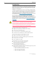
Rapier Layer 3 Gigabit Switch Software Release 2.1.0 3 • Rapier Switch Software Reference • NSM Safety and Statutory Information • NSM Quick Install Guide • NSM Hardware Reference • PIC Safety and Statutory Information • PIC Quick Install Guide • PIC Hardware Reference Rapier Switch Hardware Platform The Rapier 24 combines high performance Layer 2 switching and Layer 3 IP switching with full multiprotocol routing capabilities in a single cost-effective package.
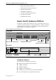
Release Note ■ 1 x RS-232 asynchronous serial port for switch management, with RS-232 DB9 cable for connection to terminal or PC. ■ 2 x Uplink bays supporting Gigabit Ethernet uplink modules ■ 1 x NSM (Network Service Module) bay ■ A high performance 32-bit PAC slot for PCI accelerator card ■ 110-240V AC power supply and optional redundant power supply (RPS) ■ Support for the full AR switching and routing software suite ■ 1.
Rapier Layer 3 Gigabit Switch Software Release 2.1.0 5 Note that this software release does not support hot swapping, so the switch must be powered down before an NSM is installed or removed. In future software releases, the Hot Swap button will be used to power down the NSM bay to allow hot swapping. Uplink Modules Each of the two uplink module expansion bays can support an optional Gigabit uplink module.
Release Note configuration. PICs can be used interchangeably with Allied Telesyn’s AR700 Series routers. Power Supply The Rapier 24 has an AC power supply, which adapts to any power supply in the range of 110-240 VAC 50-60 Hertz input. It also has an inlet for connection to an optional redundant power supply (RPS) unit, AT-PWR8000. Future releases of the software will include power supply monitoring.
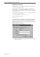
Rapier Layer 3 Gigabit Switch Software Release 2.1.0 7 Graphical User Interface The switch includes a built-in web browser based GUI for configuring and monitoring Layer 2 switching features. To enable the GUI, an IP address must be assigned to a switch interface. Connect a terminal or a PC running terminal emulation software (for instance Windows Terminal or HyperTerminal) to the RS-232 Terminal Port, and log in to the manager account.
Release Note Figure 3: Rapier 24 Welcome page While using the Rapier GUI, use the buttons on the pages to navigate, not the browser’s Back and Forward buttons, to ensure that configuration information is stored correctly. If you have not yet changed the initial manager password, we recommend that you do this now. Make sure you remember the new password, as there is no way to retrieve it if it is lost. To leave the Rapier GUI, click the Exit button on the Welcome page.
Rapier Layer 3 Gigabit Switch Software Release 2.1.0 9 command processor when it is ready to receive commands. A USER level prompt looks like: > while a MANAGER prompt looks like: Manager > and a SECURITY OFFICER prompt looks like: SecOff > See the Operations Chapter of the AR Series Router Reference Manual at http://www.alliedtelesyn.co.nz/support/rapier/ for more information about creating new accounts with user, manager and security officer privileges.
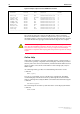
Release Note Figure 4: Example output from the SHOW FILE command. Filename Device Size Created Locks -----------------------------------------------------------------------1mac.scp flash 527 08-Nov-2000 12:46:00 0 86s-210.rez flash 1690736 14-Sep-2000 14:11:56 0 config.scp flash 64 10-Nov-2000 23:26:31 0 hdroute.scp flash 374 08-Nov-2000 12:46:00 0 loadup.scp flash 173 20-Nov-2000 07:03:30 0 loadup1.scp flash 224 14-Nov-2000 14:11:56 0 quick.scp flash 2036 08-Nov-2000 12:46:00 0 release.
Rapier Layer 3 Gigabit Switch Software Release 2.1.0 11 Figure 5: Example of output from the SHOW SYSTEM command Switch System Status Time 14:29:17 Date 12-Sep-2000.
Release Note executed the command processor can determine whether the password value is clear text or an MD5 digest. Using the Built in Editor The switch has a built-in full-screen text editor for editing script files stored on the switch file subsystem. Scripts can be run manually, or run when a trigger automatically activates on some specified events in the switch. See “Triggers” on page 50, and the Trigger Facility chapter in the AR Series Router Reference Manual at http://www.alliedtelesyn.co.
Rapier Layer 3 Gigabit Switch Software Release 2.1.0 13 The temporary and preferred installs are completely configurable. Both the release and an associated patch may be set. The release may be EPROM or a release stored in FLASH. The three different installs are required to handle the following situations: ■ A default install is required to handle the case when only the EPROM release is present.
Release Note The PATCH parameter specifies the patch file for this install, and is a file name of the form device:filename.ext. The patch file is stored in FLASH. The default value for the device field is FLASH. If the patch name is not given, the patch file information for a given install is removed and only the release file will be loaded for the install. A patch file can not be set up for an install unless a release file is already set up, or a release file is specified in the same command.
Rapier Layer 3 Gigabit Switch Software Release 2.1.0 15 SET LOADER [DELAY=delay|DEFAULT] [DESTINATION={FLASH|DEFAULT}] [FILE=filename] [HTTPPROXY={hostname|ipadd|DEFAULT}] [METHOD={HTTP|TFTP|WEB|WWW|ZMODEM|NONE|DEFAULT}] [ASYN=port|DEFAULT] [PROXYPORT=1..65535|DEFAULT] [SERVER={hostname|ipadd|DEFAULT}] This command sets default values for the name of the file to load, the network host to load it from, and the memory location in which to store the file.
Release Note transfer is terminated by the first control character received that is not a CR or LF character. The FILE parameter is not valid when METHOD is set to ZMODEM. The PORT parameter is not valid when METHOD is set to HTTP, WEB, WWW, TFTP or NONE. If DEFAULT is specified, this parameter is set to the factory default, which is TFTP. The ASYN parameter specifies the asynchronous port via which the file will be downloaded, when the METHOD parameter is set to ZMODEM or NONE.
Rapier Layer 3 Gigabit Switch Software Release 2.1.0 17 When the download has completed, the presence of the files in FLASH can be displayed with the command: SHOW FILE This shows the file 86s-210.rez is present. 2. Test the release. The release can now be tested, using the command: SET INSTALL=TEMPORARY RELEASE=86s-210.REZ The install information can be checked with the command: SHOW INSTALL The switch is then rebooted, and the install is checked again.
Release Note ■ Packet Forwarding at wire speed. ■ Store and Forward switching mode. ■ Autonegotiation of link speed and duplex mode for 10/100 Mbps speed on all 100BASE TX ports. ■ Autonegotiation of duplex mode for 10/100 and gigabit Ethernet ports. ■ Automatic, configurable MAC address learning and ageing, supporting up to 8191 MAC addresses per switch. ■ Switch Filtering. ■ Flow Control. ■ Broadcast Storm Protection. ■ Spanning Tree Protocol.
Rapier Layer 3 Gigabit Switch Software Release 2.1.0 19 where: ■ port-list is a port number, a range of port numbers (specified as n-m), or a comma separated list of port numbers and/or ranges. Port numbers start at 1 and end at m, where m is the highest numbered switch Ethernet port. (including uplink ports). To display information about the settings of the switch port, use the command: SHOW SWITCH PORT=port-list Figure 8: Example output from the SHOW SWITCH PORT command.
Release Note Table 5: Parameters in the output of the SHOW SWITCH PORT command Parameter Meaning Port The number of the switch port. Link state The link state of the port, one of “Up” or “Down”. Uptime The count in seconds of the elapsed time since the port was last reset or initialised. Port Media Type The MAC entity type as defined in the MIB object ifType. Configured speed/duplex The port speed and duplex mode configured for this port.
Rapier Layer 3 Gigabit Switch Software Release 2.1.0 21 Resetting Ethernet ports at the hardware level discards all frames queued for reception or transmission on the port, and restarts autonegotiation of port speed and duplex mode. This clears any packets stuck in a queue, for instance after a broadcast storm, and may sometimes make a non-operational port operational again.
Release Note senders of traffic on ports which have too many packets in the input queue can be informed of the situation and made to restrict the flow of packets. Flow control for Ethernet ports consists of two mechanisms. The mechanism for a given port is dependent on the duplex mode of the port. For full duplex ports, flow control is achieved by sending a special PAUSE MAC frame out the port, which tells the sending device not to send any more frames for a random period of time.
Rapier Layer 3 Gigabit Switch Software Release 2.1.0 23 The Rapier switch supports up to 6 trunk groups, of up to 8 10/100 Ethernet ports each. The two 2 gigabit Ethernet ports can also be grouped together to form a trunk group. Ports do not have to be contiguous. Port trunking can be used between any two Rapier switches.
Release Note By default, packet storm protection is disabled. It can be enabled, and each of the limits can be set using the command: SET SWITCH PORT=port-list [BCLIMIT={NONE|limit}] [DLFLIMIT={NONE|limit}] [MCLIMIT={NONE|limit}] The BCLIMIT parameter specifies a limit on the rate of reception of broadcast packets for the port(s). The value of this parameter represents a per second rate of packet reception above which packets will be discarded, for broadcast packets.
Rapier Layer 3 Gigabit Switch Software Release 2.1.0 25 On the Rapier switch, packet storm protection limits cannot be set for each individual port, but can be set for each processing block of ports. On the Rapier 24 switch the processing blocks are ports 1-8, 9-16, 17-24, and a processing block each for the uplink ports 25 and 26.
Release Note The ability to decouple logical broadcast domains from the physical wiring topology offers several advantages, which include: ■ Workstations can be grouped logically or functionally, regardless of their physical location on the network. ■ VLAN memberships can be changed at any time by software configuration, without moving the workstations physically, or by simply moving a cable from one port to another.
Rapier Layer 3 Gigabit Switch Software Release 2.1.0 27 VLANs are created and destroyed with the commands: CREATE VLAN=vlanname VID=2..4094 DESTROY VLAN={vlanname|2..4094|ALL} The VLAN parameter specifies a unique name for the VLAN. This name can be more meaningful than the VID, to make administration easier. The VLAN name is only used within the switch; it is not transmitted to other VLAN-aware devices, or used in the Forwarding Process or kept in the Forwarding Database.
Release Note Figure 10: VLANS with untagged ports Port 1 Port 2 Port 3 Marketing VLAN Switch Training VLAN Port 14 Port 15 Port 16 411 VLAN-FG1 To display the VLANs configured on the switch, use the command: SHOW VLAN[={vlanname|1..4094|ALL}] Figure 11: Example output from the SHOW VLAN command.
Rapier Layer 3 Gigabit Switch Software Release 2.1.0 29 Table 8: Parameters displayed in the output of the SHOW VLAN command Parameter Meaning Tagged Ports A list of tagged ports that belong to the VLAN. Spanning Tree The name of the Spanning Tree entity to which the VLAN belongs. Attachments This section shows information about other modules and protocols using the VLAN module. Module The name of the software module attached to the VLAN.
Release Note admitted. The switch only forwards the frame over those ports that belong to the VLAN specified by this VID. When the switch forwards a frame over a port to another VLAN-aware device (for instance, another switch), it adds a VLAN tag (the same VID) to the frame. When it forwards the frame over a port to a VLAN-unaware device, it transmits it as a VLAN-untagged frame, not including the VID in the frame.
Rapier Layer 3 Gigabit Switch Software Release 2.1.0 31 Figure 12: Tagged VLANs Training VLAN VID=3 Port 3 Port 22 Port 21 Port 26 Switch A Switch B Port 25 Port 1 Port 2 Admin VLAN VID=2 Port 4 Port 23 Marketing VLAN VID=4 411 VLAN-aware server VLAN-FG2 To display the VLANs configured on the switch, use the command: SHOW VLAN[={vlanname|1..4094|ALL}] Some additional information can be displayed which may help with trouble shooting your network.
Release Note Figure 13: Example output from the SHOW VLAN DEBUG command Vlan Enabled Debug Modes Output Timeout -----------------------------------------------------------Vlan1 PKT 16 60 -----------------------------------------------------------Vlan Enabled Debug Modes Output Timeout -----------------------------------------------------------Vlan4094 None ------------------------------------------------------------ Table 9: Parameters in the output of the SHOW VLAN DEBUG command Parameter Meaning V
Rapier Layer 3 Gigabit Switch Software Release 2.1.0 33 The Ingress Rules When a frame first arrives at a port, the Ingress Rules for the port check the VLAN tagging in the frame to determine whether it will be discarded or forwarded to the Learning Process. The first check depends on whether the Acceptable Frames parameter is set to Admit All Frames or to Admit Only VLAN Tagged Frames. If it is set to Admit Only VLAN Tagged Frames, then any incoming frames with a null VLAN Identifier (VID) are discarded.
Release Note untagged frames admitted by the ACCEPTABLE parameter are admitted, since they have the VID of the VLAN for which the port in an untagged member. If OFF is specified, Ingress Filtering is disabled, and no frames are discarded by this part of the Ingress Rules. The default setting is OFF.
Rapier Layer 3 Gigabit Switch Software Release 2.1.0 35 Forwarding occurs only if the port on which the frame was received is in the Spanning Tree ‘Forwarding’ state. The destination address is then looked up in the Forwarding Database for the VLAN. If the destination address is not found, the switch floods the frame on all ports in the VLAN except the port on which the frame was received.
Release Note Figure 14: Example output from the SHOW SWITCH FILTER command. Switch Filters -------------------------------------------------------------------------------Dest. VLAN Age Action St.
Rapier Layer 3 Gigabit Switch Software Release 2.1.0 37 which are only sent when there are no frames waiting to be sent in any of the higher QOS egress queues. Which traffic class is sent to which QOS egress queue can be configured with this command: SET SWITCH QOS=P1,P2,P3,P4,P5,P6,P7,P8 The Rapier 24 has four QOS egress queues. It has a default mapping of priority levels to QOS egress queues as defined in IEEE Standard 802.1Q (Table 11).
Release Note The Egress Rules Once the Forwarding Process has determined which ports and transmission queues to forward a frame from, the Egress Rules for each port determine whether or not the outgoing frame is VLAN-tagged with its VID. (See “Virtual LANs” on page 25). Whether outgoing frames for a VLAN are tagged when transmitted from the port is configured when the port is added to the VLAN, and can be changed later, using this commands: ADD VLAN={vlanname|1..
Rapier Layer 3 Gigabit Switch Software Release 2.1.0 ■ 39 The unique parent of a switch is the LAN, to which the switch is attached, that is closest to the root bridge. The spanning tree computation is a continuous, distributed process. The algorithm uses the following steps to establish the spanning tree: 1. A unique root bridge is elected by the switches in the LAN. 2. A designated bridge is elected for each LAN in the extended LAN by the switches in the LAN. 3.
Release Note Switch port states A switch port may be in one of five states (Table 13), determined dynamically by STP (“Spanning Tree Protocol (STP)” on page 38). Table 13: Switch port states State Meaning DISABLED Switching operations are disabled on the port. In particular, the Forwarding Process and the Spanning Tree entity are disabled for transmit and receive operations on the port. LISTENING The port is enabled for receiving frames only.
Rapier Layer 3 Gigabit Switch Software Release 2.1.0 41 same STP. Within any given STP, all VLANs belonging to it use the same Spanning Tree. ■ The topology of the VLAN is dynamic. The structure of the VLAN may change due to new devices requesting or releasing the services available via the VLAN. The dynamic nature of VLANs has the advantages of flexibility and bandwidth conservation, at the cost of network management complexity. Multiple Spanning Trees in a VLAN environment have not been standardised.
Release Note there can be delays in adapting to a change in the topology, for instance when a fault occurs. The FORWARDDELAY parameter is used to prevent temporary loops in the network occurring in the briefly unstable topology while a topology change is propagated through the network.
Rapier Layer 3 Gigabit Switch Software Release 2.1.0 43 Figure 16: Example output from the SHOW STP command. Spanning Tree Protocol -----------------------------------------------------------Name .................. VLAN members .......... Status ................ Number of Ports ....... Number Enabled ...... Number Disabled ..... Bridge Identifier ..... Designated Root ....... Max Age ............... Hello Time ............ Forward Delay ......... Bridge Max Age ........ Bridge Hello Time .....
Release Note Table 14: Parameters in the output of the SHOW STP command Parameter Meaning Root Port The port number of the root port for the switch. If the switch is the Root Bridge this parameter is not valid and is not shown. Root Path Cost The cost of the path to the Root from this switch. If the switch is the Root Bridge this parameter is not valid and is not shown. Max Age The maximum age of received Configuration Message information before it is discarded.
Rapier Layer 3 Gigabit Switch Software Release 2.1.0 45 particular port is likely to reduce the traffic over the LAN connected to it. This may be appropriate if the LAN has lower bandwidth, or if there are reasons for limiting the traffic across it. To modify the STP port pathcost, use the command: SET STP PORT={port-list|ALL} PATHCOST=1..1000000 [otherparameters...] The PATHCOST parameter sets the path cost for each port. The PATHCOST for a LAN port should be set to a maximum of 65535.
Release Note Table 15: Parameters displayed in the output of the SHOW STP PORT command Parameter Meaning Port The number of the port. State The state of the port; one of “Disabled”, “Blocking”, “Listening”, “Learning” or “Forwarding”. STP The name of the STP that the port is a member of. STP Status The status of the STP that the port is a member of; one of “ON” or “OFF”. Pathcost The pathcost of the port. Designated Cost The designated cost for the port.
Rapier Layer 3 Gigabit Switch Software Release 2.1.0 47 Table 17: Parameters in the output of the SHOW STP COUNTER command Parameter Meaning Transmit: TCN BPDU The number of Topology Change Notification BPDUs transmitted. Discarded: Port Disabled The number of BPDUs discarded because the port that the BPDU was received on was disabled. Discarded: Invalid Protocol The number of STP packets that had an invalid Protocol Identifier field or invalid Protocol Version Identifier field.
Release Note Figure 18: Example output from the SHOW STP DEBUG command Port Enabled Debug Modes Output Timeout -----------------------------------------------------------Port1 MSG, PKT, STATE 16 42 -----------------------------------------------------------Port Enabled Debug Modes Output Timeout -----------------------------------------------------------Port2 STATE 16 12345 -----------------------------------------------------------Port Enabled Debug Modes Output Timeout -------------------------------
Rapier Layer 3 Gigabit Switch Software Release 2.1.0 49 IGMP is enabled using the command: ENABLE IP IGMP IGMP snooping is then enabled on a VLAN using the command: ENABLE IP IGMP INTERFACE={VLAN-vlanname|VLANvid} The switch will snoop IGMP packets transiting the VLAN and only forward multicast packets to the ports which have seen a membership report from network devices connected to those ports, instead of being forwarded to all ports belonging to the VLAN. The command: SET IP IGMP TIMEOUT=1..
Release Note Table 20: Parameters in the output of the SHOW IP IGMP command. (Continued) Parameter Meaning Interface Name The name of an IP interface, followed by “(DR)” if the interface is acting as the designated router. Group List A list of multicast group memberships for this interface. Group. The group multicast address. Last Adv. The last host to advertise the membership report.
Rapier Layer 3 Gigabit Switch Software Release 2.1.0 Event 51 LIGHTON Description The fibre port specified by the PORT parameter has just gained coherent light. Parameters The following command parameter(s) must be specified in the CREATE/SET TRIGGER commands: Script Parameters Parameter Description PORT=port The port on which the event will activate the trigger.
Release Note Figure 20: Example output from the SHOW IP INTERFACE command. Interface Type IP Address Bc Fr PArp Filt RIP Met. SAMode IPSc Pri. Filt Pol.Filt Network Mask MTU VJC GRE OSPF Met. DBcast Mul. -------------------------------------------------------------------------------LOCAL Not Set - n --- --------- --vlan11 Static 192.168.163.39 1 y On --- 01 Pass -----255.255.255.0 1500 --- 0000000001 No On ppp1 Dynamic 0.0.0.0 1 y --- 01 Pass -----255.255.255.
Rapier Layer 3 Gigabit Switch Software Release 2.1.0 53 Figure 22: Example output from the SHOW IPX CIRCUIT command. IPX CIRCUIT information Name ......................... Status ....................... Interface .................... Network number ............... Station number ............... Link state ................... Cost in Novell ticks ......... Type20 packets allowed ....... On demand .................... Circuit 1 enabled vlan11 (802.
Release Note Figure 23: Example output from the SHOW APPLE PORT command. Appletalk Port Details -----------------------------------Port Number .............. 1 Interface ................ vlan11 ifIndex .................. 1 Node ID .................. 217 Network Number ........... 22 Network Range Start ...... 22 Network Range End ........ 22 State .................... ACTIVE Seed ..................... NO Seed Network Start ....... 0 Seed Network End ......... 0 Hint .....................
Rapier Layer 3 Gigabit Switch Software Release 2.1.0 55 Layer 3 LAN/WAN Routing In addition to Layer 2 and Layer 3 switching, the Rapier switch implements almost all of the AR routing software suite from Allied Telesyn’s AR series of routers, providing a wide array of multiprotocol routing, security and network management features. IP routing is performed at wire-speed. Other Layer 3 routing is performed by the CPU, and increasing the routing load on the CPU decrease its performance.
Release Note ■ Virtual Router Redundancy Protocol (VRRP) for fault tolerant internet gateways (on NSM ports only) ■ IPsec ■ ISAKMP Key Management ■ Data Compression ■ Predictor Data Compression ■ STAC Data Compression ■ Nemesis Stateful Inspection Firewall ■ SecureShell Remote Management ■ Resource Reservation Protocol (RSVP) ■ L2TP ■ Telnet client and server.
Rapier Layer 3 Gigabit Switch Software Release 2.1.0 57 Authentication failure traps and link state traps can be enabled using the commands: ENABLE SNMP AUTHENTICATE_TRAP ENABLE INTERFACE=interface LINKTRAP where interface is the name of an interface, such as vlan11. The command: SHOW SNMP displays the current state and configuration of the SNMP agent (Figure 25 on page 57). Figure 25: Example output from the SHOW RSVP INTERFACE command. SNMP configuration: Status ..........................
Release Note Availability The Rapier 24 switch is supplied with Software Release 2.1.0 installed. During the field trial, software upgrades and upgrade information for the Rapier 24 will be available from the Allied Telesyn Research web site http://www.alliedtelesyn.co.nz/support/rapier/. The LOAD command can be used to download software upgrades directly from the Allied Telesyn Research web site to the switch’s FLASH memory.