AT-TQ1402 Series Wireless Access Point AT-TQ1402 AT-TQm1402 AT-T Q1 402 2.4G Hz 5GHz LAN PWR 4680 Installation Guide 613-002709 Rev.
Copyright 2019 Allied Telesis, Inc. All rights reserved. No part of this publication may be reproduced without prior written permission from Allied Telesis, Inc. Allied Telesis and the Allied Telesis logo are trademarks of Allied Telesis, Incorporated. All other product names, company names, logos or other designations mentioned herein are trademarks or registered trademarks of their respective owners. Allied Telesis, Inc.
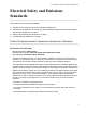
AT-TQ1402 Series Wireless Access Point Installation Guide Electrical Safety and Emissions Standards This product meets the following standards: “Federal Communications Commission Interference Statement” “European Union Restriction of the Use of Certain Hazardous Substances (RoHS) in Electrical and Electronic Equipment” on page 4 “Safety and Electromagnetic Emissions” on page 4 “Translated Safety Statements” on page 7 Federal Communications Commission Interference Statement Declaration of Co
Caution FCC Caution: Any changes or modifications not expressly approved by the party responsible for compliance could void the user's authority to operate this equipment. E80 Avertissement Avertissement de la FCC: Les changements ou modifications non expressément approuvés par la partie responsable de la conformité pourraient annuler l'autorité de l'utilisateur à utiliser cet équipement. E80 This transmitter must not be co-located or operating in conjunction with any other antenna or transmitter.
AT-TQ1402 Series Wireless Access Point Installation Guide Wire Communication • IEEE 802.1 • IEEE 802.3 • IEEE 802.3u • IEEE 802.3x • IEEE 802.3af Wireless Communication • IEEE 802.11 DSSS • IEEE 802.11a OFDM • IEEE 802.11b DSSS/FHSS • IEEE 802.11g OFDM • IEEE 802.11n OFDM • IEEE 802.
Electro Magnetic Interference (EMI) • FCC part15 Subpart B/ Class B • EN55032 Class B • CISPR 32 • VCCI Class B • VCCI-CISPR 32:2016 • AS/NZS CISPR 32 Electro Magnetic Susceptibility (EMS) - EN55024 and EN55035 • IEC 61000-4-2:2008 • IEC 61000-4-3: 2006+A1:2007+A2:2010 • IEC 61000-4-4:2012 • IEC 61000-4-5:2017 • IEC 61000-4-6:2013 • (IEC 61000-4-8:2009) • IEC 61000-4-11:2014/AMD:2017 • IEC 61000-3-2:2014 • IEC 61000-3-3:2013 FCC • 47 CFR Part15, subpart C • 47 CFR Part15, subpart E CE • RED Directive 201
AT-TQ1402 Series Wireless Access Point Installation Guide RCM • CISPR 32:2015/COR1:2016 • AS/NZS CISPR 32: 2015 • AS/NZS 4268: 2017 Translated Safety Statements Important: The indicates that a translation of the safety statement is available in a PDF document titled Translated Safety Statements on the Allied Telesis website at www.alliedtelesis.com/ support.
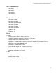
Table of Contents Preface ............................................................................................................................................................15 Product Description ......................................................................................................................................19 Overview ....................................................................................................................................................
List of Figures Figure 1: Top View .......................................................................................................................................... Figure 2: Front Edge View ............................................................................................................................... Figure 3: Back Edge View ...............................................................................................................................
List of Tables Table 1. Primary Port for Power Source ......................................................................................................... 25 Table 2. LED Status Information .................................................................................................................... 26 Table 3. Shipping Box Components ............................................................................................................... 32 Table 4. Physical Specifications ...............
Preface This guide contains the hardware installation instructions for the AT-TQ1402 Series Wireless Access Point.
Preface Safety Symbols Used in this Document This document uses the following conventions. Note Notes provide additional information. Caution Cautions inform you that performing or omitting a specific action may result in equipment damage or loss of data. Warning Warnings inform you that performing or omitting a specific action may result in bodily injury.
AT-TQ1402 Series Wireless Access Point Installation Guide Contacting Allied Telesis If you need assistance with this product, you may contact Allied Telesis technical support by going to the Support & Services section of the Allied Telesis web site at www.alliedtelesis.com/support.
Chapter 1 Product Description This chapter describes the hardware components of the AT-TQ1402 Series Wireless Access Point.
Chapter 1: Product Description Overview The AT-TQ1402 Series Access Point is a dual-band access point designed to connect wireless devices to your local area network. This device can be mounted on a ceiling, wall or tabletop.
AT-TQ1402 Series Wireless Access Point Installation Guide The front edge view of the AT-TQ1402 Series is illustrated in Figure 2. 4683 Mounting Bracket Thumb Screw Hole Figure 2. Front Edge View The back edge view of the AT-TQ1402 Series is illustrated in Figure 3. POWER RESET DC IN LAN CONSOLE POE DC Input DC Power Button Jack Reset Ethernet Button LAN-PoE Port 4682 Console Serial Port Figure 3. Back Edge View Note The DC Power Button only controls power into the DC-IN jack only.
Chapter 1: Product Description Features This section lists the main features of the AT-TQ1402 Series Wireless Access Point. Hardware Features 22 The hardware features are as follows: One fixed 10/100/1000 BASE-T port (RJ-45) in dual function mode to support IEEE standard 802.3af compliance powered device (PD) mode of PoE. Based on parallel 12 DC in power plane from PD power and DC-IN power source, and the power source supplies to AP from PoE and external power supply unit (PSU) in parallel.
AT-TQ1402 Series Wireless Access Point Installation Guide Management Access LAN Port Access to manage the software features of the access point are: Standalone HTTPS The AT-TQ1402 Series Access Point is equipped with one Ethernet port LAN. The LAN port is capable of receiving PoE power (powered device port) as the primary power or standing by as the backup power source for an external power supply unit. Note For more information, see “Redundant Power Supply” on page 25.
Chapter 1: Product Description Speed The LAN port can operate at 10/100 Mbps or 1000 Mbps. The speed is set automatically with Auto-Negotiation. You cannot disable Auto-Negotiation on the port. Note The LAN port should be connected to a network device that also adjusts its speed with Auto-Negotiation. If the network device does not support Auto-Negotiation, the LAN port operates at 10 Mbps, which may reduce network performance.
AT-TQ1402 Series Wireless Access Point Installation Guide Redundant Power Supply The AT-TQ1402 Series Access Point offers a redundant power supply system. In addition to the power supply through the DC-IN jack, the access point has one PoE-capable LAN port (LAN). The external power supply connected to the DC-IN jack is the primary power source for the unit. If the power supply unit on the access point fails, power is supplied to the access point via the PoE port.
Chapter 1: Product Description LEDs The LEDs on the AT-TQ1402 Series Access Point top panel display the status information. This LED display status information is given in Table 2. Table 2. LED Status Information LED State GREEN AT-TQ1402 Series is powered ON and operating normally. AMBER System is booting up. OR A fault condition has been detected. BLINKING AMBER The firmware is upgrading. OFF AT-TQ1402 Series is not receiving power. GREEN A valid link is established on the port.
AT-TQ1402 Series Wireless Access Point Installation Guide Cable Specifications The AT-TQ1402 Series Access Point is connected to your local area network with Ethernet cables from Ethernet ports LAN. Refer to “Cable Specifications” on page 48 for the specifications of these cables.
Chapter 2 AT-TQ1402 Series Wireless Access Point Installation This chapter describes how to install the AT-TQ1402 Series Access Point.
Chapter 2: AT-TQ1402 Series Wireless Access Point Installation Review Safety Precautions Please review the following safety precautions before you begin to install the access point. Important: Safety statements that have the symbol are translated into multiple languages in the Translated Safety Statements document, which is available at www.alliedtelesis.com/library.
AT-TQ1402 Series Wireless Access Point Installation Guide Warning This equipment shall be installed in a Restricted Access location. E45 Warning FCC Caution: Any changes or modifications not expressly approved by the party responsible for compliance could void the user's authority to operate this equipment. E80 Note The AT-TQ1402 Series must be supplied by: 1.
Chapter 2: AT-TQ1402 Series Wireless Access Point Installation Unpack Shipping Box Contents To unpack the AT-TQ1402 Series Access Point from the shipping box, perform the following procedure: 1. Remove all components from the shipping box. Note Store the packaging material in a safe location so that if you need to return the unit to Allied Telesis, you will have the original shipping material available. 2. Verify that all components listed in Table 3 are included in your shipping box.
AT-TQ1402 Series Wireless Access Point Installation Guide Installation Guidelines Review the following guidelines before installing the access point: The ceiling or wall mounting surface must be of proper material to accommodate the screws and strong enough to support the weight of the access point and cables. (Refer to Table 4 on page 45 for the product weight.) Connect the Ethernet cable and power cord to the access point before installing the access point on the ceiling or wall.
Chapter 2: AT-TQ1402 Series Wireless Access Point Installation Install Access Point This section contains the following topics: General Installation Guidelines Table Top Installation “General Installation Guidelines” on page 34 “Table Top Installation” on page 34 “Ceiling or Wall - Mounting Bracket Installation” on page 35 “Install Ethernet Cable and External DC Power Supply” on page 40 “External AC/DC Power Adapter Installation” on page 40 “Install Anti-theft Device” on page 41
AT-TQ1402 Series Wireless Access Point Installation Guide 3. The installation of your AT-TQ1402 Series Access Point on the table top surface is now complete. Ceiling or Wall Mounting Bracket Installation This section explains how to install the access point on a ceiling or wall that consists of a hard surface.
Chapter 2: AT-TQ1402 Series Wireless Access Point Installation Pre-Fit Mounting Bracket on AT-TQ1402 Series Access Point To pre-fit the access point on the mounting bracket, perform the following procedure: 1. Install the two screws (provided) in the bottom side of the access point chassis. Refer to Figure 5. LE E SO PO N O C 1 LA C IN D ET ES R ER W PO 4686 Figure 5. Attach Screws to Access Point Chassis 2.
AT-TQ1402 Series Wireless Access Point Installation Guide 3. Tighten the screws so that they touch the mounting bracket plate and then loosen them by approximately 1/4 turn. Note Adjust the access point chassis screws so they are loose enough to slide into the narrow end of the mounting bracket keyhole, but tight enough to be hold the access point close without rattling against the mounting bracket. 4.
Chapter 2: AT-TQ1402 Series Wireless Access Point Installation 2. Using the mounting bracket as a template, mark the two key-hole slots with a pencil in the location and orientation where you want to install the access point. Refer to the arrows in Figure 8. 4440 4436 Ceiling Wall Figure 8. Mark and Pre-Drill Holes for Key-Hole Slots 3. Pre-drill the two marked locations for the keyhole slots on the hard-surface ceiling or wall and install two M4 screws and anchors (if required).
AT-TQ1402 Series Wireless Access Point Installation Guide 5. Secure the physical position of the mounting bracket by pre-drilling holes through the two existing open bracket mounting holes in the opposite corners from the key-hole slots. Refer to the arrows in Figure 10. 4441 4437 Ceiling Wall Figure 10. Pre-Drill Holes for Mounting Bracket 6. Install and tighten two M4 screws (not provided) in the holes prepared in Step 5. The physical position of the bracket is now stationary. Refer to Figure 11.
Chapter 2: AT-TQ1402 Series Wireless Access Point Installation Install Ethernet Cable and External DC Power Supply The Ethernet and power cable needs to be connected before attaching the access point to the mounting bracket. Note Refer to “Cable Specifications” on page 48 when selecting Ethernet cable. 1. Connect the Ethernet cable into the RJ-45 LAN port. Refer to Figure 12. This Ethernet port is capable of receiving PoE power. POWER RESET DC IN LAN CONSOLE POE 4696 Figure 12.
AT-TQ1402 Series Wireless Access Point Installation Guide 2. Plug the DC plug of the Power Adapter into the DC-IN jack on the access point. Refer to Figure 13. POWER RESET DC IN LAN CONSOLE POE 4693 Figure 13. Connect External AC/DC Power Adapter Cable 3. Connect the external power supply AC plug to an appropriate AC power source. 4. On the AT-TQ1402 Series chassis, push the DC Power Button to the “IN” position to turn ON the power supply at the chassis.
Chapter 2: AT-TQ1402 Series Wireless Access Point Installation 2. If you are installing your AT-TQ1402 Series on a table top surface, your unit is now ready for use. 3. If you are installing your AT-TQ1402 Series on the ceiling or wall installation, go to “Ceiling or Wall - Attach Chassis to Mounting Bracket” on page 42 section. Ceiling or Wall Attach Chassis to Mounting Bracket Perform this procedure to complete the ceiling or wall installation by attaching the chassis to the mounting bracket. 1.
AT-TQ1402 Series Wireless Access Point Installation Guide 4690 Figure 16. Seat Access Point onto Mounting Bracket 3. Tighten the bracket thumbscrew into the front of the chassis until it is securely fastened. Refer to Figure 17. 4691 Figure 17. Securely Fasten Chassis to Mounting Bracket with Thumbscrew 4. The ceiling or wall installation is now complete and your AT-TQ1402 Series Access Point is ready for use.
Chapter 2: AT-TQ1402 Series Wireless Access Point Installation Start Initial Management Session This section contains an abbreviated version of the procedure to start the initial management session. For complete instructions, refer to the AT-TQ1402 Series Wireless Access Point Series User’s Guide. The wireless access point firmware includes a DHCP client. The default setting for the client is enabled.
Appendix A Technical Specifications This appendix contains the following sections: “Physical Specifications” “Environmental Specifications” “Power Specifications” on page 46 “Cable Specifications” on page 48 “LAN Port Specifications and Pinouts” on page 49 Physical Specifications Table 4. Physical Specifications Parameter Specification Dimensions (W x D x H) 163 mm x 165 mm x 40.5 mm (6.42 in. x 6.50 in. x 1.59 in.) Weight (AT-TQ1402 Series with mounting bracket) 567 g (1.
Appendix A: Technical Specifications Power Specifications Input Power Specifications The power specifications for the AT-TQ1402 Series Access Point are given in Table 6. Table 6. Input Power Specifications Parameter Rated Input Voltage External Power Supply Specifications Specification 12 VDC Maximum Input Current 0.7 A Average Input Current 0.52 A The external power supply must be capable of powering the AT-TQ1402 Series Access Point by meeting the specifications given in Table 7. Table 7.
AT-TQ1402 Series Wireless Access Point Installation Guide Note The AT-MWS0091 (WA-24Q12R) external power supply is not supplied or shipped with the AT-TQ1402 Series Access Point product. PoE Power Requirements The AT-TQ1402 Series Access Point power requirements for the LAN PoE port are given in Table 8. Table 8. PoE Power Requirements Parameter Specification AT-TQ1402 Series 12.
Appendix A: Technical Specifications Cable Specifications The AT-TQ1402 Series Access Point Ethernet cable requirements for the LAN ports are listed in Table 9. Table 9. LAN Port Twisted Pair Cable Requirements Cable Type Standard TIA/EIA 568-A-compliant Category 5 shielded or unshielded cabling with 100 ohm impedance and 100 MHz frequency.
AT-TQ1402 Series Wireless Access Point Installation Guide LAN Port Specifications and Pinouts Port Specifications The AT-TQ1402 Series Access Point port specifications are shown in Table 10. Table 10. LAN Port Specifications Connector Port Pinouts Specification Standards - LAN IEC603-7 (10/100/1000 Base T) PoE standard - LAN IEEE 802.3af (class 3) The pin signal definitions for 10/100/1000 Mbps Ethernet traffic are as follows. Figure 19 illustrates the pin layout of the LAN ports. Figure 19.
Appendix A: Technical Specifications Table 12 lists the pin signals for the MDI-X configuration at 10/100 Mbps. Table 12. MDI-X Pin Signals (10Base-T or 100Base-TX) Pin Signal 1 RX+ 2 RX- 3 TX+ 6 TX- Table 13 lists the pin signals when the LAN port is operating at 1000 Mbps. Table 13.
Appendix B Regulatory Statements This appendix contains the following regulatory statements: “Federal Communication Commission Interference Statement” on page 52 “Europe - EU Declaration of Conformity” on page 54 51
Appendix Appendix B: Regulatory Statements Federal Communication Commission Interference Statement This device complies with Part 15 of the FCC Rules. Operation is subject to the following two conditions: (1) This device may not cause harmful interference, and (2) this device must accept any interference received, including interference that may cause undesired operation. This equipment has been tested and found to comply with the limits for a Class B digital device, pursuant to Part 15 of the FCC Rules.
AT-TQ1402 Series Wireless Access Point Installation Guide Radiation Exposure Statement This equipment complies with FCC radiation exposure limits set forth for an uncontrolled environment. This equipment should be installed and operated with minimum distance 20 cm between the radiator and your body.
Appendix Appendix B: Regulatory Statements Europe - EU Declaration of Conformity Hereby, Allied Telesis declares that the radio equipment type [AT-TQ1402 and AT-TQm1402] is in compliance with Directive 2014/53/EU. Operating Frequencies and Maximum Transmission Power Levels The operating frequencies and maximum transmission power levels for wireless devices operated in the EU are listed below: - 2412-2472 MHz: 19.78dBm (Non-Beamforming) - 5150-5250 MHz: 22.11 dBm (Beamforming), 22.