x510 Series Gigabit Ethernet Switches AT-x510-28GTX AT-x510-28GPX AT-x510-28GSX AT-x510-52GTX AT-x510-52GPX Installation Guide for Virtual Chassis Stacking 613-001780 Rev.
Copyright 2013 Allied Telesis, Inc. All rights reserved. No part of this publication may be reproduced without prior written permission from Allied Telesis, Inc. Allied Telesis and the Allied Telesis logo are trademarks of Allied Telesis, Incorporated. All other product names, company names, logos or other designations mentioned herein are trademarks or registered trademarks of their respective owners. Allied Telesis, Inc.
Electrical Safety and Emissions Standards This product meets the following standards. U.S. Federal Communications Commission Radiated Energy Note: This equipment has been tested and found to comply with the limits for a Class A digital device pursuant to Part 15 of FCC Rules. These limits are designed to provide reasonable protection against harmful interference when the equipment is operated in a commercial environment.
Translated Safety Statements Important: Safety statements that have the symbol are translated into multiple languages in the Translated Safety Statements document at www.alliedtelesis.com/support.
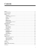
Contents Preface .............................................................................................................................................................................. 11 Document Conventions .......................................................................................................................................................12 Contacting Allied Telesis ...................................................................................................................
Contents Stacking Transceivers......................................................................................................................................................... 48 Stacking Port Topologies .................................................................................................................................................... 50 Master and Member Switches .........................................................................................................................
Figures Figure 1: Front Panels of the AT-x510-28GTX and AT-x510-28GPX Switches ...................................................................19 Figure 2: Front Panels of the AT-x510-28GSX, AT-x510-52GTX, and AT-x510-52GPX Switches......................................20 Figure 3: Back Panel of the AT-x510-28GTX, AT-x510-52GTX, and AT-x510-28GSX Switches ........................................21 Figure 4: Back Panel of the AT-x510-28GPX and AT-x510-52GPX Switches ......................................
Figures Figure 50: Switch Initialization Messages (Continued) .......................................................................................................100 Figure 51: Removing the Dust Plug from an SFP Slot........................................................................................................105 Figure 52: Installing an SFP Transceiver............................................................................................................................
Tables Table 1: Twisted Pair Cable for the 10/100/1000Base-T Ports ...........................................................................................24 Table 2: IEEE Powered Device Classes ..............................................................................................................................26 Table 3: Twisted Pair Cable Requirements for the 10/100Base-TX Ports at 10 or 100Mbps ..............................................
Tables 10
Preface This guide contains the installation instructions for the x510 Series of Layer 2+ and Basic Layer 3, Gigabit Ethernet switches.
Preface Document Conventions This document uses the following conventions: Note Notes provide additional information. Caution Cautions inform you that performing or omitting a specific action may result in equipment damage or loss of data. Warning Warnings inform you that performing or omitting a specific action may result in bodily injury.
x510 Series Installation Guide for Virtual Chassis Stacking Contacting Allied Telesis If you need assistance with this product, you may contact Allied Telesis technical support by going to the Support & Services section of the Allied Telesis web site at www.alliedtelesis.com/support.
Preface 14
Chapter 1 Overview This chapter contains the following sections: “Features” on page 16 “Front and Back Panels” on page 19 “Management Panel” on page 22 “10/100/1000Base-T Twisted Pair Ports” on page 23 “Power Over Ethernet” on page 25 “SFP+ Slots” on page 30 “Stacking SFP+ Slots” on page 31 “eco-friendly Button” on page 32 “LEDs” on page 33 “USB Port” on page 41 “Console Port” on page 42 “Power Supplies” on page 43 Note This guide explains how to install the
Chapter 1: Overview Features Here are the switches and their features: x510 Models 10/100/1000 Mbps Twisted Pair Ports Power Over Ethernet SFP Slots Here are the x510 Series switches: AT-x510-28GTX AT-x510-28GPX AT-x510-28GSX AT-x510-52GTX AT-x510-52GPX Here are the basic features of the 10/100/1000 Mbps twisted pair ports: 24 or 48 ports per switch 10Base-T, 100Base-TX, and 1000Base-T compliant IEEE 802.
x510 Series Installation Guide for Virtual Chassis Stacking Supports single-port BiDi 1000Base-LX SFP transceivers Supports 1000Base-ZX SFP transceivers Supports 10/100/1000Base-T twisted pair transceivers Note SFP transceivers must be purchased separately. For a list of supported transceivers, contact your Allied Telesis distributor or reseller.
Chapter 1: Overview LEDs Installation Options MAC Address Table Management Software and Interfaces Management Methods 18 AT-StackOP/9.
x510 Series Installation Guide for Virtual Chassis Stacking Front and Back Panels The front panels of the x510 Series switches are shown in Figure 1 and Figure 2 on page 20. AT-x510-28GTX Management Panel 10/100/1000Base-T Ports SFP+ Slots SFP+ or Stacking Slots AT-x510-28GPX 10/100/1000Base-T Ports with PoE Management Panel SFP+ Slots SFP+ or Stacking Slots Figure 1.
Chapter 1: Overview AT-x510-52GSX Management Panel 10/100/1000Base-T and 100/1000Base-FX Transceiver Slots SFP+ Slots SFP+ or Stacking Slots AT-x510-52GTX 10/100/1000Base-T Ports Management Panel SFP+ Slots SFP+ or Stacking Slots AT-x510-52GPX 10/100/1000Base-T Ports with PoE Management Panel SFP+ Slots SFP+ or Stacking Slots Figure 2.
x510 Series Installation Guide for Virtual Chassis Stacking Figure 3 shows the back panel of the AT-x510-28GTX, AT-x510-52GTX, and AT-x510-28GSX Switches. AC Power Connector (Power Supply 2) AC Power Connector (Power Supply 1) Figure 3. Back Panel of the AT-x510-28GTX, AT-x510-52GTX, and ATx510-28GSX Switches Figure 4 shows the back panel of the AT-x510-28GPX and AT-x51052GPX Switches. AC Power Connector (Power Supply 2) AC Power Connector (Power Supply 1) Figure 4.
Chapter 1: Overview Management Panel Figure 5 identifies the components in the management panel on the x510 Series switches. Console Management Port Switch ID LED eco-friendly Button USB Port Figure 5.
x510 Series Installation Guide for Virtual Chassis Stacking 10/100/1000Base-T Twisted Pair Ports The switches have 24 or 48 10/100/1000Base-T ports. Speed The ports can operate at 10, 100, or 1000 Mbps. The speeds may be set manually using the management software or automatically with AutoNegotiation (IEEE 802.3u), the default setting. Note The ports must be set to Auto-Negotiation to function at 1000 Mbps and are not compatible with devices that are not IEEE 802.3u compliant.
Chapter 1: Overview The MDI and MDI-X settings do not apply when ports are operating at 1000 Mbps. Maximum Distance Cable Requirements The ports have a maximum operating distance of 100 meters (328 feet). The cable requirements of the ports are given in Table 1. Table 1. Twisted Pair Cable for the 10/100/1000Base-T Ports Cable Type Standard TIA/EIA 568-Bcompliant Category 3 shielded or unshielded cabling with 100 ohm impedance and a frequency of 16 MHz.
x510 Series Installation Guide for Virtual Chassis Stacking Power Over Ethernet The AT-x510-28GPX and AT-x510-52GPX Switches feature Power over Ethernet (PoE) on the 10/100/1000Base-T ports. PoE is used to supply power to network devices over the same twisted pair cables that carry the network traffic. The main advantage of PoE is that it can make it easier to install a network. The selection of a location for a network device is often limited by whether there is a power source nearby.
Chapter 1: Overview Table 2. IEEE Powered Device Classes Maximum Power Output from a Switch Port Class Cable Requirements PD Power Range 0 15.4W 0.44W to 12.95W 1 4.0W 0.44W to 3.84W 2 7.0W 3.84W to 6.49W 3 15.4W 6.49W to 12.95W 4 30.0W 12.95W to 25.5W The cable requirements for ports operating at 10 or 100Mbps are given in Table 3. Table 3.
x510 Series Installation Guide for Virtual Chassis Stacking The cable requirements for ports operating at 1000Mbps are given in Table 4. Table 4. Twisted Pair Cable Requirements for the 10/100/1000Base-T Ports at 1000Mbps 1000Mbps Cable Type Power Budget NonPoE PoE PoE+ Standard TIA/EIA 568-B-compliant Category 3 shielded or unshielded cabling with 100 ohm impedance and a frequency of 16 MHz.
Chapter 1: Overview simultaneously as long as the total is below its power budget. If the total exceeds the available power budget, you should consider reducing the number of PoE devices so that all of the devices receive power. Otherwise, the switch powers a subset of the devices, based on port prioritization. The switch can handle different power requirements on different ports. This enables you to connect different classes of PoE equipment to the ports on the switch.
x510 Series Installation Guide for Virtual Chassis Stacking of the power supplies fail or lose power. If you limit the power requirements of the critical devices connected to a switch to less than 185 watts, the PoE power provided by a single power supply, a switch will have sufficient power to support the critical devices even if it has only one functional power supply. Wiring Implementation The IEEE 802.
Chapter 1: Overview SFP+ Slots The switches have four SFP+ slots that support the following types of SFP 1000Mbps and SFP+ 10Gbps transceivers: 1000Base-SX/LX SFP transceivers Single-port BiDi 1000Base-LX SFP transceivers 1000Base-ZX SFP transceivers 10Gbps, 10GBase-SR/LR fiber optic transceivers 10Gbps AT-SP10TW direct connect twinax cables with SFP+ transceiver-style connectors You may use the transceivers to connect switches to other network devices over large distances, build high-s
x510 Series Installation Guide for Virtual Chassis Stacking Stacking SFP+ Slots Two of the four SFP+ slots on the front panel of the switch can be used with stacking transceivers to create a VCStack of up to four switches. The switches of a VCStack act as a single virtual unit. They synchronize their actions so that switching operations, like spanning tree protocols, virtual LANs, and static port trunks, span across all the units and ports.
Chapter 1: Overview eco-friendly Button You may turn off the port LEDs to conserve electricity when you are not monitoring the switch. The LEDs are toggled with the eco-friendly button on the front panel of the switch or the ECOFRIENDLY LED and NO ECOFRIENDLY LED commands in the Global Configuration mode of the command line interface. The switch is said to be operating in a low power mode when the LEDs are turned off.
x510 Series Installation Guide for Virtual Chassis Stacking LEDs Here are descriptions of the LEDs. LEDs for the Twisted Pair Ports Each twisted pair port on the AT-x510-28GTX and AT-x510-52GTX Switches has two LEDs that display link, activity and duplex mode information. The LEDs are shown in Figure 6. Link/Activity LED Duplex Mode LED Link/Activity LED Duplex Mode LED Figure 6.
Chapter 1: Overview Table 5. LEDs on the 10/100/1000Base-T Ports on the AT-x510-28GTX and AT-x510-52GTX Switches LED Link/ Activity LED Duplex Mode LED State Description Solid Green A port has established a 1000 Mbps link to a network device. Flashing Green A port is transmitting or receiving data at 1000 Mbps. Solid Amber A port has established a 10 or 100 Mbps link to a network device. Flashing Amber A port is transmitting or receiving data at 10 or 100 Mbps.
x510 Series Installation Guide for Virtual Chassis Stacking Link/Activity LED PoE LED Link/Activity LED PoE LED Figure 7. LEDs for the 10/100/1000Base-T Ports on the AT-x510-28GPX and AT-x510-52GPX Switches The LEDs are described in Table 6. Table 6. LEDs on the 10/100/1000Base-T Ports on the AT-x510-28GPX and AT-x510-52GPX Switches LED Link/ Activity LED State Description Solid Green A port has established a 1000 Mbps link to a network device.
Chapter 1: Overview Table 6. LEDs on the 10/100/1000Base-T Ports on the AT-x510-28GPX and AT-x510-52GPX Switches (Continued) LED PoE LEDs for the SFP Slots State Description Green The switch is detecting a powered device (PD) on the port and is delivering power to it. Solid Amber The switch has shutdown PoE+ on the port because of a fault condition. Flashing Amber The switch is detecting a PD on the port but is not delivering power to it because the maximum power budget has been reached.
x510 Series Installation Guide for Virtual Chassis Stacking The LEDs are described in Table 7. Table 7. SFP Slot LEDs on the AT-x510-28GSX Switch LED Link/Activity LEDs for the SFP+ Slots State Description Off The slot is empty, the SFP transceiver has not established a link to a network device, or the LEDs are turned off. To turn on the LEDs, use the eco-friendly button. Solid green The SFP transceiver has established a link at 10 Mbps, 1000 Mbps or 10 Gbps to a network device.
Chapter 1: Overview Table 8. SFP+ Slot LEDs LED Link/Activity LEDs for the Stacking Slots State Description Off The slot is empty, the SFP or SFP+ transceiver has not established a link to a network device, or the LEDs are turned off. To turn on the LEDs, use the ecofriendly button. Solid green The SFP or SFP+ transceiver has established a link at 1000 Mbps or 10 Gbps to a network device. Flashing green The SFP+ transceiver is receiving or transmitting packets to a network device at 10 Gbps.
x510 Series Installation Guide for Virtual Chassis Stacking Switch ID LED The Switch ID LED, shown in Figure 10, displays the ID number of the switch. A stand-alone switch has the ID number 0. Switches in a VCStack have the numbers 1 to 4. Chapter 7, “Powering On the Stack” on page 89 has the procedure for verifying and, if necessary, changing the ID number of the switch. Switch ID LED Figure 10.
Chapter 1: Overview The switch displays the letter “F” for fault on the ID LED if it encounters one of the following problems: A cooling fan has failed. One of the power supplies has failed. The internal temperature of the switch has exceeded the normal operating range and the switch may shut down. Note You can use the SHOW SYSTEM ENVIRONMENT command in the command line interface to identify the source of the problem.
x510 Series Installation Guide for Virtual Chassis Stacking USB Port The management panel has a USB port. You may use the port to store configuration files on flash drives and to restore configuration files to switches whose settings have been lost or corrupted, or to quickly configure replacement units. You may also use the port and flash drives to update the management firmware on the switches. The port is USB2.0 compatible.
Chapter 1: Overview Console Port The Console port is used to establish a management session with the switch to configure its features and parameter settings. This type of management uses serial RS-232 and is commonly referred to as local or out-of-band management because it is not conducted over your network. To perform local management, you must be at the location of the switch and must use the management cable included with the switch.
x510 Series Installation Guide for Virtual Chassis Stacking Power Supplies The x510 Series switches have two AC power supplies with separate AC connectors on the back panels. The power supplies, which are not fieldreplaceable, provide a switch with power redundancy and protect against interruptions to network operations in the event one of the power supplies loses power or fails. Power redundancy is available only when both AC connectors on a switch are connected to power sources.
Chapter 1: Overview 44
Chapter 2 Virtual Chassis Stacking The sections in this chapter are: “Overview” on page 46 “Stacking Slots” on page 47 “Stacking Transceivers” on page 48 “Stacking Port Topologies” on page 50 “Master and Member Switches” on page 54 “Specifying Ports in the Command Line Interface” on page 56 Note For more information on the VCStack feature, refer to the Stacking Introduction and Stacking Commands chapters in the Software Reference for x510 Series Switches, AlliedWare Plus Operating S
Chapter 2: Virtual Chassis Stacking Overview The Virtual Chassis Stacking (VCStack) feature allows you to connect up four x510 Series switches to form a virtual switch in which the devices function as a single networking unit. The benefits of the VCStack feature are: 46 Simplifies management - You can manage the devices of the stack as a single unit, rather than individually. Your local and remote management sessions automatically give you management access to all the devices.
x510 Series Installation Guide for Virtual Chassis Stacking Stacking Slots The x510 Series Switches come with two stacking slots. The slots are the last two SFP+ slots on the switches and are labeled “S1/27” and “S2/28” on the 28-port switches and “S1/51” and “S2/52” on the 52-port switches. The slots have two functions.
Chapter 2: Virtual Chassis Stacking Stacking Transceivers You connect the switches of the VCStack with the stacking transceivers listed in Table 10 and shown in Figure 13. Table 10. Stacking Transceivers Stacking Transceiver Model Cable Type Operating Distance AT-StackXS/1.0 Twinax cable 1 meter AT-StackOP/0.3 62.5/125 µm multimode fiber optic cable 33 meters (108 feet) 50/125 µm multimode fiber optic cable 300 meters (984 feet) 9/125 µm singlemode fiber optic cable 9 kilometers AT-StackOP/9.
x510 Series Installation Guide for Virtual Chassis Stacking Here are the transceiver guidelines: The stacking transceivers may only be used in the stacking slots and only with the VCStack feature. You may not use the transceivers as regular networking ports. The AT-StackOP/0.3 and AT-StackOP/9.0 transceivers must be connected to other AT-StackOP/0.3 and AT-StackOP/9.0 transceivers. The transceivers do not work with other types of network devices.
Chapter 2: Virtual Chassis Stacking Stacking Port Topologies The switches of a stack are connected with the S1 and S2 ports and the stacking transceivers shown in Figure 13 on page 48. There are two wiring configurations. The first topology is called the linear topology. In this topology the switches are connected with a single pathway. A stacking transceiver in one switch is connected to a stacking transceiver in the next switch, which is connected to the next switch, and so on.
x510 Series Installation Guide for Virtual Chassis Stacking Figure 15. Stack of Four Switches in the Linear Topology The second topology is called the ring topology. It is similar to the linear topology, except that the unused stacking ports on the end switches of the stack are connected to form a physical loop. This topology is more resilient than the linear topology because there are two pathways through the stack.
Chapter 2: Virtual Chassis Stacking Figure 16. Stack of Two Switches in the Ring Topology Figure 17 on page 53 is an example of a stack of four switches in the ring topology.
x510 Series Installation Guide for Virtual Chassis Stacking Figure 17. Stack of Four Switches in the Ring Topology The topologies are the same in terms of network speed and performance. However, the ring topology is the recommended wiring configuration because of the secondary path through the stacking ports. The two pathways protect the switches of the stack against the loss of communications due to a failure of a stacking port, cable, or switch.
Chapter 2: Virtual Chassis Stacking Master and Member Switches The stack has one master switch. The functions of the master switch include: Coordinating and monitoring stack operations. Verifying that the switches are using the same version of management software. It automatically downloads its management software over the stacking cables to switches with different software versions. Verifying that the switches have different ID numbers.
x510 Series Installation Guide for Virtual Chassis Stacking ID Numbers Each switch must be assigned an ID number. The range is 1 to 4 and the default is 1. The ID numbers are displayed on the ID LEDs on the front panels of the units. You may assign the numbers yourself or you can let the master switch assign the numbers automatically., as explained in Chapter 7, “Powering On the Stack” on page 89.
Chapter 2: Virtual Chassis Stacking Specifying Ports in the Command Line Interface The command line interface in the management software on the switch has a parameter that you use to specify the individual ports. The parameter is the PORT parameter and Figure 18 shows its format. port1.0.n Stack ID Module ID Port Number Figure 18. PORT Parameter in the Command Line Interface The first number is the switch’s ID number. The ID numbers of switches in a stack are displayed on their ID LEDs.
Chapter 3 Beginning the Installation The chapter contains the following sections: “Reviewing Safety Precautions” on page 58 “Choosing a Site for the Switches” on page 62 “Planning a Stack” on page 63 “Unpacking the Switch” on page 65 57
Chapter 3: Beginning the Installation Reviewing Safety Precautions Please review the following safety precautions before beginning the installation procedure. Note Safety statements that have the symbol are translated into multiple languages in the Translated Safety Statements document at www.alliedtelesis.com/support. Warning Class 1 Laser product. L1 Warning Do not stare into the laser beam.
x510 Series Installation Guide for Virtual Chassis Stacking Warning Class I Equipment. This equipment must be earthed. The power plug must be connected to a properly wired earth ground socket outlet. An improperly wired socket outlet could place hazardous voltages on accessible metal parts. E4 Note Pluggable Equipment. The socket outlet shall be installed near the equipment and shall be easily accessible.
Chapter 3: Beginning the Installation Caution Risk of explosion if battery is replaced by an incorrect type. Replace only with the same or equivalent type recommended by the manufacturer. Dispose of used batteries according to the manufacturer’s instructions. Attention: Le remplacement de la batterie par une batterie de type incorrect peut provoquer un danger d’explosion. La remplacer uniquement par une batterie du même type ou de type équivalent recommandée par le constructeur.
x510 Series Installation Guide for Virtual Chassis Stacking Warning Reliable earthing of rack-mounted equipment should be maintained. Particular attention should be given to supply connections other than direct connections to the branch circuits (e.g., use of power strips). E37 Warning To reduce the risk of electric shock, the PoE ports on this product must not connect to cabling that is routed outside the building where this device is located.
Chapter 3: Beginning the Installation Choosing a Site for the Switches Observe these requirements when planning the installation of the switches of a stack. If you plan to install the switches in an equipment rack, check to be sure that the rack is safely secured so that it will not tip over. Devices in a rack should be installed starting at the bottom, with the heavier devices near the bottom of the rack.
x510 Series Installation Guide for Virtual Chassis Stacking Planning a Stack Here are the guidelines to planning a stack: A stack can have up to four x510 Series switches. A stack can have different models of x510 Series switches. Any x510 Series switch model can be the master switch of a stack. Switches connected with AT-StackXS/1.0 stacking cables should be installed in a standard 19-inch equipment rack and not more than one meter apart, the length of the stacking cable.
Chapter 3: Beginning the Installation Table 11. Operating Distances of the AT-StackOP/0.3 Transceiver Fiber Type 64 Minimum Modal Bandwidth @ 850 nm (MHz*km) Operating Range 62.
x510 Series Installation Guide for Virtual Chassis Stacking Unpacking the Switch Figure 19 lists the items that come with the switch. If any item is missing or damaged, contact your Allied Telesis sales representative for assistance. One 2 m (6.6 ft) local management cable with RJ-45 (8P8C) and DB-9 (D-sub 9-pin) connectors. Two rack mounting brackets Two regional AC power cords Eight bracket screws Figure 19.
Chapter 3: Beginning the Installation 66
Chapter 4 Installing the Switches on a Table or in an Equipment Rack The procedures in this chapter are: “Installing the Switches on a Table or Desktop” on page 68 “Installing the Switch in an Equipment Rack” on page 69 67
Chapter 4: Installing the Switches on a Table or in an Equipment Rack Installing the Switches on a Table or Desktop You may install the switches on a table or desktop. Here are the guidelines to selecting a site: The table should be level and stable. The power outlets should be located near the switches and be easily accessible. The site should allow for easy access to the ports on the front of the switches, so that you can easily connect and disconnect cables, and view the port LEDs.
x510 Series Installation Guide for Virtual Chassis Stacking Installing the Switch in an Equipment Rack This procedure requires the following items: Eight bracket screws (included with the switch) Two equipment rack brackets (included with the switch) Flat-head screwdriver (not provided) Cross-head screwdriver (not provided) Four standard equipment rack screws (not provided) Installation guidelines may be found in “Choosing a Site for the Switches” on page 62.
Chapter 4: Installing the Switches on a Table or in an Equipment Rack 3. Turn the switch over. 4. Attach the two rack mount brackets to the sides of the switch using the eight bracket screws included with the unit. Figure 22 on page 70 and Figure 23 on page 71 illustrate the four possible bracket positions. Figure 22.
x510 Series Installation Guide for Virtual Chassis Stacking Figure 23. Attaching the Equipment Rack Brackets (Continued) 5. While another person holds the switch in the equipment rack, secure it using standard equipment rack screws (not provided), as shown in Figure 24. Figure 24. Mounting the Switch in an Equipment Rack 6. Repeat this procedure to install the remaining switches in the stack. 7.
Chapter 4: Installing the Switches on a Table or in an Equipment Rack 72
Chapter 5 Verifying the Status of VCStack The procedures in this chapter are: “Verifying the Status of VCStack” on page 74 “Activating the VCStack Feature” on page 75 73
Chapter 5: Verifying the Status of VCStack Verifying the Status of VCStack Before you install the stacking transceivers to build the stack, you should first test the switches to determine whether the VCStack feature is enabled or disabled, and enable it on any units where it is disabled. On new switches, the feature should be activated because that is the default setting. But on switches that were previously used as stand-alone units, the feature is probably disabled and needs to be enabled.
x510 Series Installation Guide for Virtual Chassis Stacking Activating the VCStack Feature Perform the following two procedures to activate the VCStack feature on switches that display the number “0” on their ID LEDs in the previous procedure. The tasks assume that you are continuing directly from the previous procedure and that the switch is powered on.
Chapter 5: Verifying the Status of VCStack Note The port settings are for a DEC VT100 or ANSI terminal, or an equivalent terminal emulator program. 4. Press Enter. You are prompted for a user name and password. 5. If this is the initial management session of the switch, enter “manager” as the user name and “friend” as the password. The user name and password are case sensitive. The local management session starts when the User Exec mode prompt, shown in Figure 26. is displayed. awplus> Figure 26.
x510 Series Installation Guide for Virtual Chassis Stacking 3. Enter the STACK ENABLE command to activate VCStack on the switch, as shown in Figure 29: awplus(config)# stack enable % The device needs to be restarted for this change to take effect. awplus(config)# Figure 29. Activating VCStack with the STACK ENABLE Command 4. Enter the EXIT command to return to the Privileged Exec mode, as shown in Figure 30. awplus(config)# exit awplus# Figure 30.
Chapter 5: Verifying the Status of VCStack 9. Check the ID LED and do one of the following: 78 If the ID LED is displaying the number 1, 2, 3, or 4, VCStack is now enabled on the switch. Power off the switch by disconnecting the power cord and repeat the procedures in this chapter on the next switch. If there are no further switches to test, go to Chapter 6, “Cabling the Stacking Ports” on page 79. If the ID LED is still displaying “0,” repeat this procedure.
Chapter 6 Cabling the Stacking Ports This chapter contains the following procedures: “Cabling Switches with AT-StackXS/1.0 Transceivers” on page 80 “Cabling Switches with AT-StackOP/0.3 or AT-StackOP/9.
Chapter 6: Cabling the Stacking Ports Cabling Switches with AT-StackXS/1.0 Transceivers To cable the switches of the stack with AT-StackXS/1.0 transceivers, perform the following procedure: Warning A transceiver can be damaged by static electricity. Be sure to observe all standard electrostatic discharge (ESD) precautions, such as wearing an antistatic wrist strap, to avoid damaging the device. 1. Remove the dust plug from the S1 slot on the top switch of the stack, as shown in Figure 33. Figure 33.
x510 Series Installation Guide for Virtual Chassis Stacking Figure 34. Removing the Dust Cover from the AT-StackXS/1.0 Transceiver 4. Position the transceiver with the release tab on top and slide the transceiver into the slot, as shown in Figure 35 on page 82.
Chapter 6: Cabling the Stacking Ports Release tab Figure 35. Installing the AT-StackXS/1.0 Transceiver in Slot S1 5. Remove the dust cover from the S2 slot in the next switch in the stack as shown in Figure 36 on page 83. Note The cable must crossover to different slots on the switches. The stack will not work if you connect two S1 or S2 slots together.
x510 Series Installation Guide for Virtual Chassis Stacking Figure 36. Removing the Dust Plug from the S2 Slot 6. Remove the dust cover from the connector on the other end of the transceiver. 7. Position the transceiver with the release tab on the bottom and slide it into the slot until it clicks into place, as shown in Figure 37 on page 84.
Chapter 6: Cabling the Stacking Ports Figure 37. Installing the AT-StackXS/1.0 Transceiver in Slot S2 8. Repeat this procedure to connect additional switches to the stack with AT-StackXS/1.0 transceivers. 9. To create the redundant path with the ring topology shown in Figure 16 on page 52 and Figure 17 on page 53, connect a stacking cable to the empty stacking slots on the top and bottom switches. 10.
x510 Series Installation Guide for Virtual Chassis Stacking Cabling Switches with AT-StackOP/0.3 or AT-StackOP/9.0 Transceivers For guidelines to cabling the switches with AT-StackOP/0.3 or ATStackOP/9.0 fiber optic transceivers, refer to “Planning a Stack” on page 63. To cable switches with fiber optic transceivers, perform the following procedure: 1. Remove a dust cover from either the S1 or S2 slot on the switch. 2.
Chapter 6: Cabling the Stacking Ports Figure 39. Installing the AT-StackOP/0.3 or AT-StackOP/9.0 Transceiver 4. Remove the dust cover from the transceiver, as shown in Figure 40 on page 87.
x510 Series Installation Guide for Virtual Chassis Stacking Figure 40. Removing the Dust Cover from a Stacking Transceiver 5. Verify the position of the handle on the transceiver. If the transceiver is in the S1 slot, the handle should be in the upright position, as shown in Figure 41. If the transceiver is in the S2 slot, the handle should be in the down position. SFP Handle Figure 41. Positioning the Handle in the Upright Position 6.
Chapter 6: Cabling the Stacking Ports Figure 42. Connecting the Fiber Optic Cable to the Stacking Transceiver 7. Repeat this procedure if the switch is to have two stacking transceivers. 8. Repeat this procedure on the other switches of the stack to install their stacking transceivers. The connections must crossover such that a transceiver in slot 1 connects to a transceiver in slot 2. 9. After you connect the stacking cables to all the switches, go to Chapter 7, “Powering On the Stack” on page 89.
Chapter 7 Powering On the Stack This chapter contains the following procedures: “Powering On the Switches Individually” on page 90 “Powering On the Switches Simultaneously” on page 93 “Verifying the Stack” on page 95 “Monitoring the Initialization Processes” on page 98 Perform “Powering On the Switches Individually” on page 90 if you want to control the assignment of the ID numbers to the switches of the stack. The numbers are assigned in the order in which you power on the units.
Chapter 7: Powering On the Stack Powering On the Switches Individually This procedure explains how you can control the assignment of the ID numbers of the switches by powering on the units one at a time during the initial power-on sequence. The first switch is assigned ID number 1, the next unit is assigned ID number 2, and so on.
x510 Series Installation Guide for Virtual Chassis Stacking Figure 43. Plugging in the AC Power Cords Consider the following items as you power on the switch: Connecting the two power cords to power sources that are on different circuits will provide power redundancy to the switch in the event a circuit fails. Refer to “Power Specifications” on page 116 for the power specifications of the switches. Warning Power cord is used as a disconnection device.
Chapter 7: Powering On the Stack As the new switch boots up, the first switch, which has the ID number 1 and at this point is the master switch of the stack, notifies the new switch that its current ID number is already being used and that it should change its number to the next available number, which is 2. The new switch responses by automatically changing its ID number to 2 and reboots.
x510 Series Installation Guide for Virtual Chassis Stacking Powering On the Switches Simultaneously If you want the switches of the stack to use their MAC addresses to automatically assign the ID numbers during the initial power on sequence, all you have to do is power them on simultaneously, rather than one at a time as in the previous procedure. Here are the steps the switches perform: They initialize their management software and compare their MAC addresses.
Chapter 7: Powering On the Stack Warning Power cord is used as a disconnection device. To de-energize equipment, disconnect the power cord. E3 Note Pluggable Equipment. The socket outlet shall be installed near the equipment and shall be easily accessible. E5 2. Wait two or three minutes for the switches to select a master switch and to assign the ID numbers. At this point, the stack is operational.
x510 Series Installation Guide for Virtual Chassis Stacking Verifying the Stack To verify stack operations, perform the following procedure: 1. Establish a local management session on any switch in the stack. For instructions, refer to “Starting a Local Management Session” on page 75. 2. From the User Exec mode, enter the SHOW STACK command: awplus> show stack The command lists the switches in the stack. An example is show in Figure 44.
Chapter 7: Powering On the Stack Setting the Priority Numbers Otherwise, go to Chapter 8, “Cabling the Networking Ports” on page 101, to continue with the installation. This procedure is optional. It explains how to configure the priority settings of the switches. Changing the priority settings protects the stack configuration should you ever power on the stack with a new member switch that has a lower MAC address than an existing master or member switch.
x510 Series Installation Guide for Virtual Chassis Stacking awplus(config)# exit awplus# Figure 46. Returning to the Privileged Exec Mode 4. Enter the WRITE command to save your change in the configuration file. The switch displays the confirmation prompt in Figure 47. awplus# write Building configuration ... [OK] awplus# Figure 47. Saving the Priority Values with the WRITE Command 5. To end the management session, enter the EXIT command. 6.
Chapter 7: Powering On the Stack Monitoring the Initialization Processes You may monitor the initialization sequence of the stack by connecting a terminal or computer that has a terminal emulator program to the Console port on any switch in the stack. You will see the messages in Figure 48 here to Figure 50 on page 100. Bootloader 2.0.11 loaded Press for the Boot Menu Reading filesystem... Loading flash:x510-5.4.2a-20120727-1.rel... Verifying release... OK Booting... Starting base/first...
x510 Series Installation Guide for Virtual Chassis Stacking Received event poefw.done Starting base/portmapper... [ OK ] Starting base/reboot-stability... [ OK ] Starting base/autofs-card... [ OK ] Received event syslog.done Checking system reboot stability... [ OK ] Starting base/cron... [ OK ] Starting base/appmond... [ OK ] Starting hardware/openhpi... [ OK ] Starting hardware/timeout... [ OK ] Starting base/inet... [ OK ] Starting base/modules...
Chapter 7: Powering On the Stack Received event network.activated Loading default configuration Warning: flash:/default.cfg does not exist, loading factory defaults. .. done! Received event network.configured awplus login: 21:12:34 awplus VCS[734]: Duplicate member-ID 1 detected for 0015.774f.ed30 and 0011.2233.4455 21:12:34 awplus VCS[734]: Automatically renumbering member-1 (0015.774f.ed30), selecting unused member-ID... 21:12:52 awplus VCS[734]: Renumbering member-1 (0015.774f.
Chapter 8 Cabling the Networking Ports This chapter contains the following procedures: “Cabling the Twisted Pair Ports” on page 102 “Installing SFP and SFP+ Transceivers” on page 104 101
Chapter 8: Cabling the Networking Ports Cabling the Twisted Pair Ports Here are the guidelines to cabling the 10/100/1000Base-T twisted pair ports: 102 The cable specifications for the 10/100/1000Base-T twisted pair ports are listed in Table 1 on page 24. The connectors on the cables should fit snugly into the ports, and the tabs should lock the connectors into place. The default setting for the wiring configurations of the ports is autoMDI/MDI-X.
x510 Series Installation Guide for Virtual Chassis Stacking The default duplex mode setting of Auto-Negotiation is not appropriate for ports connected to network devices that do not support Auto-Negotiation and have a fixed duplex mode. You should disable Auto-Negotiation on those ports and set their duplex modes manually to avoid the possibility of duplex mode mismatches.
Chapter 8: Cabling the Networking Ports Installing SFP and SFP+ Transceivers This section contains guidelines and procedures for installing SFP and SFP+ transceivers. The installation procedures are listed here: “Installing SFP Modules in the AT-x510-28GSX Switch” on page 105 “Installing SFP and SFP+ Modules” on page 108 Here are general installation guidelines for SFP and SFP+ transceivers: SFP and SFP+ transceivers are hot-swappable. You may install them while the chassis is powered on.
x510 Series Installation Guide for Virtual Chassis Stacking Installing SFP Modules in the AT-x510-28GSX Switch To install SFP transceivers in slots 1 to 24 of the AT-x510-28GSX Switch, perform the following procedure: 1. Remove the dust plug from a transceiver slot on the switch. Refer to Figure 51. Figure 51. Removing the Dust Plug from an SFP Slot 2. Remove the transceiver from its shipping container and store the packaging material in a safe location. 3.
Chapter 8: Cabling the Networking Ports Figure 52. Installing an SFP Transceiver Note If you are ready to attach the fiber optic cable to the transceiver, continue with the next step. Otherwise, repeat steps 1 to 4 to install the remaining SFP transceivers in the switch. 5. Remove the dust cover from the transceiver, as shown in Figure 53. Figure 53. Removing the Dust Cover from an SFP Transceiver 6. Verify the position of the handle on the SFP transceiver.
x510 Series Installation Guide for Virtual Chassis Stacking SFP Handle Figure 54. Positioning the SFP Handle in the Upright Position 7. Connect the fiber optic cable to the transceiver, as shown in Figure 55. The connector on the cable should fit snugly into the port, and the tab should lock the connector into place. Figure 55. Connecting a Fiber Optic Cable to an SFP Transceiver 8. Repeat this procedure to install additional transceivers.
Chapter 8: Cabling the Networking Ports Installing SFP and SFP+ Modules To install SFP and SFP+ transceivers in slots 27 and 28 of the 28-port switches and slots 51 and 52 of the 52-port switches, perform the following procedure: 1. Remove the dust plug from a transceiver slot on the switch. Figure 56 shows the dust plug being removed from port 25 on the ATx510-28GTX Switch. Figure 56. Removing the Dust Plug from an SFP+ Slot 2.
x510 Series Installation Guide for Virtual Chassis Stacking Figure 57. Installing an SFP or SFP+ Transceiver Note If you are ready to attach the fiber optic cable to the transceiver, continue with the next step. Otherwise, repeat steps 1 to 4 to install the remaining SFP or SFP+ transceivers in the line cards. 5. Remove the dust cover from the transceiver, as shown in Figure 58. Figure 58. Removing the Dust Cover from an SFP or SFP+ Transceiver 6. Verify the position of the handle on the SFP transceiver.
Chapter 8: Cabling the Networking Ports SFP Handle Figure 59. Positioning the SFP or SFP+ Handle in the Upright Position 7. Connect the fiber optic cable to the transceiver, as shown in Figure 60. The connector on the cable should fit snugly into the port, and the tab should lock the connector into place. Figure 60. Connecting a Fiber Optic Cable to an SFP or SFP+ Transceiver 8. Repeat this procedure to install additional transceivers.
Chapter 9 Troubleshooting This chapter contains suggestions on how to troubleshoot the switch if a problem occurs. Note For further assistance, please contact Allied Telesis Technical Support at www.alliedtelesis.com/support. Problem 1: The Switch ID LED on the front of the switch is off. Solutions: The unit is not receiving power. Try the following: Verify that the power cord is securely connected to the power source and to the AC connector on the back panel of the switch.
Chapter 9: Troubleshooting Verify that VCStack is activated on the switches. For instructions, refer to Chapter 5, “Verifying the Status of VCStack” on page 73. It could be that the switches have incompatible versions of the management software. When a stack forms or a new switch is added to an existing stack, the master switch downloads its management software to member switches that do not have the same version.
x510 Series Installation Guide for Virtual Chassis Stacking If you are using SFP+ slots 27 or 28 on a 28-port switch or slots 51 and 52 on a 52-port switch, check that the VCStack feature is disabled on the switch. The VCStack feature has to be disabled before you can use the slots with regular SFP or SFP+ transceivers.
Chapter 9: Troubleshooting Use the SHOW SYSTEM ENVIRONMENT command in the Privileged Exec mode to verify that the fan is operating correctly. Verify that the location of the switch allows for adequate airflow. The unit will shutdown if it is in danger of overheating. Problem 8: The Switch ID LED on the front of the switch is flashing the letter “F.” Solutions: One or more of the following problems has occurred: A cooling fan has failed. One of the power supplies has failed.
Appendix A Technical Specifications Physical Specifications Dimensions (H x W x D) Table 12. Product Dimensions AT-x510-28GTX 4.4 cm x 44.0 cm x 32.2 cm (1.7 in. x 17.3 in. x 12.7 in.) AT-x510-28GPX 4.4 cm x 44.0 cm x 39.8cm (1.7 in. x 17.3 in. x 15.7 in.) AT-x510-28GSX 4.4 cm x 44.0 cm x 32.3 cm (1.7 in. x 17.3 in. x 12.7 in.) AT-x510-52GTX 4.4 cm x 44.0 cm x 32.2 cm (1.7 in. x 17.3 in. x 12.7 in.) AT-x510-52GPX 4.4 cm x 44.0 cm x 40.0 cm (1.7 in. x 17.3 in. x 15.7 in.) Weights Table 13.
Appendix A: Technical Specifications Environmental Specifications Table 15. Environmental Specifications Operating Temperature 0° C to 45° C (32° F to 113° F) Storage Temperature -25° C to 70° C (-13° F to 158° F) Operating Humidity 5% to 90% noncondensing Storage Humidity 5% to 95% noncondensing Maximum Operating Altitude 3,000 m (9,842 ft) Maximum Nonoperating Altitude 4,000 m (13,100 ft) Power Specifications Maximum Power Consumption Table 16.
x510 Series Installation Guide for Virtual Chassis Stacking Table 17. Input Voltages (Continued) AT-x510-52GPX AC model: 100-240 VAC,3.0A maximum, 50/60 Hz per input Certifications Table 18.
Appendix A: Technical Specifications Table 19. Pin Signals for 10 and 100 Mbps (Continued) Pin MDI Signal MDI-X Signal 3 RX+ TX+ 4 Not used Not used 5 Not used Not used 6 RX- TX- 7 Not used Not used 8 Not used Not used Table 20 lists the pin signals when a port operating at 1000 Mbps. Table 20.
x510 Series Installation Guide for Virtual Chassis Stacking RJ-45 Style Serial Console Port Pinouts Table 21 lists the pin signals of the RJ-45 style serial Console port. Table 21. RJ-45 Style Serial Console Port Pin Signals Pin Signal 1 Looped to pin 8. 2 Looped to pin 7. 3 Transmit Data 4 Ground 5 Ground 6 Receive Data 7 Looped to pin 2. 8 Looped to pin 1.
Appendix A: Technical Specifications Fiber Optic Specifications of the AT-StackOP/0.3 and AT-StackOP/9.0 Transceivers Table 22 lists the fiber optic port specifications for the AT-StackOP/0.3 transceiver. Table 22. Fiber Optic Port Specifications for the AT-StackOP/0.3 Module General Maximum Distances 33 m with 62.5/125 µm (core/ cladding) multimode fiber optic cable 300 m with 50/125 µm (core/ cladding) multimode fiber optic cable Fiber Optic Cable 50/125 µm or 62.
x510 Series Installation Guide for Virtual Chassis Stacking Table 23. Fiber Optic Port Specifications for the AT-StackOP/9.0 Transceiver (Continued) Transmitter Wavelength 1310 nm Output Optical Power -8.2 dBm min. +0.5 dBm max. Receiver Wavelength 1310 nm Maximum Sensitivity -14.4 dBm Maximum Input Power 0.
Appendix A: Technical Specifications 122