
Install guide


AT-B15 and AT-B17 Quick Install Guide
7
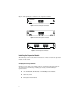
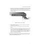
3. Insert the new module into the switch. Holding the new module with the
text on the front panel upright, carefully slide the module into the switch
slot, ensuring that the edge connector is fully engaged. Once the new
module is installed, check to be sure the front panel of the module is flush
against the switch.
Figure 5 Installing the Expansion Module
4. Using a flathead screwdriver, secure the new module to the switch by
tightening the attached screws.
5. Connect the fiber optic cable(s) to the port(s) on the newly installed
module.
6. Power on the switch by reconnecting the previously removed power sources
to the switch. The switch’s front-panel LEDs should indicate their status
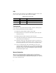
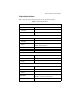
of the new connection. Check the LED indicators for the fiber ports to
ensure that they are operating properly. Refer to the table of LEDs in this
guide for a description of the LED indications. If the module does not
respond, see "Troubleshooting" below.
More details concerning connection options and network applications can be
found in the
AT-8324SX Fast Ethernet Switch Installation Guide
, which is
available from the Allied Telesyn web site.