
Installation guide


Technical Specifications
24
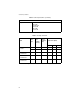
Transmitter
Output Power 62.5/125 mM
-16.8 dBm
100/140 mM
50/125 mM
-20.3 dBm
85/125 mM
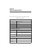
Table 9
Fiber Optic Transmitter
Model
Fiber
Type
Fiber
Optic
Diameter
(microns)
Optical
Frequency
(nm)
Launch Power (dBm)
1
1. The launch power is measured at one meter from the transmitter.
Max. Avg Min.
AT-FS201 &
AT-FS202
MMF 50/125 1310 nm -14.0 -20.3 -22.5
MMF 62.5/125 1310 nm -14.0 -16.8 -19.0
AT-FS201ST/FS1 &
AT-FS202SC/FS1
SMF 9/125 1310 nm -8.0 -11.5 -15.0
AT-FS201ST/FS2 &
AT-FS202SC/FS2
SMF 9/125 1310 nm 0.0 -3.0 -5.0
AT-FS201ST/FS3 &
AT-FS202SC/FS3
SMF 9/125 1310 nm 0.0 -2.0 -4.0
Table 8
Technical Specifications
(Continued)