
User`s guide

Section II: Local and Telnet Management
176
Table 10 lists the mappings between the eight CoS priority levels and
the four egress queues of a switch port.
For example, assume that a tagged packet with a priority level of 3
enters a port on the switch. The switch, after examining the packet’s
destination address, determines that the packet is to be sent out port 6.
The switch must now determine which of port 6’s egress queues the
packet should be stored in. It examines the priority level in the packet,
which is 3. Now the switch knows to store the packet in port 6’s low
egress queue.
You can change these mappings. For example, you might decide that
packets with a priority level of 3 need to be handled by an egress high
queue, instead of the low queue.
It needs to be noted that this determination is made when a packet is
received on the ingress port and before the frame is forwarded to the
egress port. Consequently, you need to configure this feature on the
ingress port.
For example, when you configure a switch port so that all ingress tagged
frames are handled by the egress priority queue Q2, all tagged frames
received on the port are directed to the Q2 priority egress queue on the
egress ports, regardless of the priority levels in the packets themselves.
CoS relates primarily to tagged packets rather than untagged packets
because untagged packets do not contain a priority level. By default, all
untagged packets are placed in a port’s low egress queue. But you can
override this and instruct a port’s untagged egress frames to be stored in
the high priority queue.
One last thing to note is that the AT-S39 software does not change the
priority level in a tagged packet. The packet leaves the switch with the
same priority it had when it entered. This is true even if you change the
default priority-to-egress queue mappings.
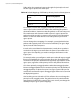
Table 10 Default Mappings of IEEE 802.1p Priority Levels to Priority Queues
IEEE 802.1p Priority
Level
Port Priority Queue
0, 1, 2, 3 low
4, 5, 6, 7 high