OmniConnect MultiModem Internet Access Device Quick Install Guide PN 613-10790-00 Rev.
Copyright ”1999 Allied Telesyn International, Corp. 960 Stewart Drive Suite B, Sunnyvale CA 94086 USA All rights reserved. No part of this publication may be reproduced without prior written permission from Allied Telesyn International, Corp. Ethernet is a registered trademark of Xerox Corporation. All other product names, company names, logos or other designations mentioned herein are trademarks or registered trademarks of their respective owners. Allied Telesyn International, Corp.
Regulatory Compliance Information Agency Approvals The following agency approvals have been obtained for the LanEdge OmniConnect MutliModem in the areas of Safety, and EMC. Note that the LanEdge OmniConnect MultiModem is not required to comply with FCC Part 68 and other telecommunications requirements since it is not directly connected to the PTT (Public Telephone and Telegraph). Safety UL 1950, CSA 22.2 No.
Regulatory Compliance Information FCC Class B Statement This device complies with Part 15 of the FCC Rules. Operation is subject to the following two conditions: (1) This device may not cause harmful interference, and (2) this device must accept any interference received, including interference that may cause undesired operation. This device has been tested and found to comply with the limits for a Class B digital device, pursuant to Part 15 of the FCC Rules.
OmniConnect MultiModem Quick Install Guide Operating Conditions for the EC The LanEdge OmniConnect MultiModem routers conforms to the Low Voltage Directive 73/23/EEC, and the EMC Directive 89/336/EEC. Operating Conditions for the United Kingdom The following apply to the LanEdge OmniConnect MutliModem when used in the UK: 1. This apparatus must be connected to a main socket outlet with a protective earth contact. 2.
Table of Contents Regulatory Compliance Information ïïïïïïïïïïïïïïïïïïïïïïïïïïïïïïïïïïïïïïïïïïïïïïïïïïïïïïïïïïïïïïïïïïïïïïïLLL Agency Approvals ...................................................................................................iii CE Marking Directive.............................................................................................iii EMC Information ...................................................................................................iii EN55022B Statement .........
Appendix A OmniConnect MultiModem Installation Guide Feedback ïïïïïïïïïïïïïïïïïïïïïïïïïïïïïïïïïïëì Appendix B Technical Support Fax Order ïïïïïïïïïïïïïïïïïïïïïïïïïïïïïïïïïïïïïïïïïïïïïïïïïïïïïïïïïïïïïïïïïïïïïïïïïïïïïïïïïïïïëê viii
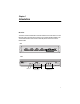
Chapter 1 Introduction Overview The OmniConnect MultiModem Internet Access Device connects users on a local Ethernet LAN to the Internet over multiple (up to three) standard modem lines. The illustrations below show the front and rear panels of the OmniConnect MultiModem.
Introduction Work sheet Before you begin installation, use the following OmniConnect work sheet and note the listed information for use during configuration. OmniConnect MultiModem Work Sheet ‰ Standard modem line(s) is installed and accessible.
OmniConnect MultiModem Quick Install Guide Topology Plan your topology including the OmniConnect. The sample topology below shows the OmniConnect MultiModem used for a group of PC users in a small office network. In this example, four 10 Mbps PC NICs and three modems are connected to the OmniConnect.
Chapter 2 Installation Use this section to verify your package contents, position the device, and configure it. Verifying OmniConnect MultiModem Package Contents ‰ One OmniConnect MultiModem Internet Access Device ‰ Accessory bag containing rubber feet and bumpers for desktop placement, and screws for wall mounting the unit ‰ This Quick Install Guide ‰ One 10Base-T Ethernet Cable ‰ One analog telephone cable ‰ One two-piece AC power adapter ‰ A CD-ROM labeled OmniStart ‰ Warranty Card.
Installation To place your LanEdge product, see the steps that follow: ‰ “To wall mount a LanEdge product” on page 6 ‰ “To place a single LanEdge product on a desktop” on page 6 ‰ “To interlock a group of LanEdge products on a desktop” on page 7 To wall mount a LanEdge product 1. Do not install the rubber feet or bumpers if you are wall mounting the product. If you previously installed the square rubber bumpers, remove them using the following step. (The round rubber feet need not be removed.
OmniConnect MultiModem Quick Install Guide To interlock a group of LanEdge products on a desktop If you are installing a LanEdge FastPrint Server, place it as the base (bottom) unit, otherwise, place the OmniConnect as the base unit. 1. Select the base unit and place it upside down on a work surface. Locate the rubber feet and bumpers from the accessory bag. Remove the paper cover from the adhesive and press a rubber foot into each round receptacle on the bottom of the unit.
Installation 4. Pry off the interlock cap at each corner of the unit: From the side of the unit, insert the tip of a small straight-slot screwdriver into the opening of the interlock cap. Press down on the screwdriver to pry the cap off. 5. Place the next unit over the base (stack) and press down on each corner to snap the units together. 6. Repeat steps 4 and 5 until all units are in the assemblage. 7.
OmniConnect MultiModem Quick Install Guide You are now ready to configure and setup the OmniConnect. To continue, see “Verify your PC Configuration” on page 10. LED Power Col Ethernet Modem Activity: 3, 2, 1 Color Green Amber Green Green State Description On The unit is receiving power, voltage is within the acceptable range, and the power supply is working. Off No power. Flashing The unit is experiencing collisions on the LAN segment.
Installation Verify your PC Configuration 1. Verify that your NIC and network driver are correctly installed; the Ethernet LED on the OmniConnect and the Link LED on the NIC should be lit. If necessary, refer to the installation manual for the NIC and the PC. 2. Verify that the TCP/IP protocol is installed and configured on each PC connected to the OmniConnect. For details concerning this, refer to the “TCP/IP Network Installation and Configuration” section of your Installation Guide.
OmniConnect MultiModem Quick Install Guide Enter Password Access to the OmniStart configuration utility is protected by a password. The default password is omni. Enter omni in the dialog box titled Password and press Enter or Next> to advance to the next screen. To change the password from the default value, click the check box 'Select this box to change the password' and then enter the new password in the New Password and Confirm New Password dialog boxes and press Next>.
Installation External Modem Setup Each enabled modem has a Setup screen. The External Modem 1 Setup screen is used to enter the Internet Service Provider (ISP) login, password and local telephone access information for External Modem 1. The Internet Service Provider (ISP) provides you a login name, password and a list of local telephone numbers. Enter this information in the spaces provided. The OmniConnect will use this information to establish a connection with the Internet Service Provider.
OmniConnect MultiModem Quick Install Guide Pressing the Dial-In Setup box allows users to dial in on a specific modem. On the OmniConnect, any one of the three external modems may be set for Dial-In. Press the Dial-In Setup box to advance to the Dial-In Setup screen. Scripting is enabled by clicking the Login Script box and advancing to the next screen. Pressing the Login Script box allows users to send a script to the ISP; see “Dial-In Setup.
Installation For telecommuters and roamers who Dial-In, you have the option of allowing PPP to assign the telecommuter (or PPP client) an IP address automatically or to assign a particular IP address. The check boxes entitled “Use the default IP address for Remote Computer” and “Use the following IP address for the Remote Computer” allow the user to select between these two options.
OmniConnect MultiModem Quick Install Guide The default DHCP address is 192.168.1.1. Once this information is entered, press the Next > button to proceed to the next screen.
Installation The Modem Parameter Verification screen verifies the configuration of the modems, the ISP information and the DNS information. Each of these parameters are checked in tern for each modem that is enabled. If there is a failure, an 'x' is displayed next to the failing item, and if the configuration is correct, a check mark is displayed.
OmniConnect MultiModem Quick Install Guide Advanced Setup Options (Finish) Once the user has reached this Advanced Setup Options screen, all the minimum parameters for a simple installation of the OmniConnect have been configured. Press the FINISH button on this screen to exit the setup program. The OmniConnect is ready for use. The various options located on this screen may be used to setup various advanced options.
Installation LanEdge Publications Visit our technical publications website at: www.alliedtelesyn.
OmniConnect MultiModem Quick Install Guide For Information Regarding Allied Telesyn International, Corp. Allied Telesyn International, Corp. 19015 North Creek Parkway Bothell, WA 98011 Tel: 1 (425) 487-8880 Fax: 1 (425) 489-9191 Allied Telesyn International, Corp. 960 Stewart Drive, Suite B Sunnyvale, CA 94086 Tel: 1 (800) 424-4284 (USA and Canada) Fax: 1 (408) 736-0100 World Wide Web http://www.alliedtelesyn.
Appendix A OmniConnect MultiModem Installation Guide Feedback Please tell us what additional information you would like to see discussed in this guide. If there are topics you would like information on that were not covered in this guide, please photocopy this page, answer the questions and fax or mail this form back to Allied Telesyn. The mailing address and fax number are at the bottom of the page. Your comments are valuable when we plan future revisions of this guide.
Appendix B Technical Support Fax Order Name __________________________________________________________________ Company _______________________________________________________________ Address ________________________________________________________________ City ________________________ State/Province_______________________________ Zip/Postal Code ___________________ Country_______________________________ Phone _______________________________Fax________________________________ Incident Summary Model number