Fiber_Book Page 1 Tuesday, February 17, 1998 1:43 PM FORMULA 8200™ Fast Ethernet Fiber Workgroup Switch Installation Guide PN 613-10688-00 Rev.
Fiber_Book Page 2 Tuesday, February 17, 1998 1:43 PM Copyright 1998 Allied Telesyn International Corp. All rights reserved. No part of this publication may be reproduced without prior written permission from Allied Telesyn International Corp. FORMULA 8200 is a trademark of Allied Telesyn International Corp. Ethernet is a registered trademark of Xerox Corporation.
Fiber_Book Page iii Tuesday, February 17, 1998 1:43 PM Table of Contents Chapter 1 Switch Installation .........................................................................................1 Overview ..............................................................................................................2 Verifying Your Switch Package ..........................................................................3 Prerequisites for Card Installation .....................................................
Fiber_Book Page iv Tuesday, February 17, 1998 1:43 PM
Fiber_Book Page 1 Tuesday, February 17, 1998 1:43 PM Chapter 1 Switch Installation This guide shows you how to install the FORMULA 8200 fiber switch from Allied Telesyn International Corp., shown in Figure 1 and Figure 2.
Fiber_Book Page 2 Tuesday, February 17, 1998 1:43 PM Switch Installation Overview The FORMULA 8200 includes the following hardware and software features: ❑ Eight or sixteen 100Base-FX, full duplex, dual SC fiber ports ❑ Flow control to autosense buffer limits on the transmit port ❑ Front panel LEDs that provide operating status and a Reset button for front panel control of switch ❑ RS-232 console port interface for local switch management or Telnet support for remote switch management ❑ Rack moun
Fiber_Book Page 3 Tuesday, February 17, 1998 1:43 PM FORMULA 8200 Fiber Switch Installation Guide Verifying Your Switch Package Your FORMULA 8200 package consists of: ❑ One FORMULA 8200 fiber switch, either the 8-port AT-8208F/SC or the 16-port AT-8216F/SC ❑ Rackmounting kit that includes brackets and screws for the rackmounting option ❑ Four feet for the desktop mounting option ❑ AC power cord (U.S.A.
Fiber_Book Page 4 Tuesday, February 17, 1998 1:43 PM Switch Installation Location Install the FORMULA 8200 on a sturdy, level surface in a ventilated area that is dust free and away from heat vents, warm air exhaust from other equipment, and direct sunlight. Avoid proximity to large electric motors or other electromagnetic equipment. Refer to Appendix A, “Product Specifications for the FORMULA 8200 Switch,” for a summary of installation specifications. Installing the FORMULA 8200 on the Desktop 1.
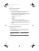
Fiber_Book Page 5 Tuesday, February 17, 1998 1:43 PM FORMULA 8200 Fiber Switch Installation Guide Installing the FORMULA 8200 in the Rack Caution When mounting the switch in a rack, do not stack units directly on top of one another. 1. If the rubber feet are attached, remove them. 2. Attach the mounting brackets to the side of the switch using the M4 x 8 mm screws provided (Figure 4). Caution Use only the M4 x 8 mm screws provided. Longer screws may contact the internal components, damaging the unit.
Fiber_Book Page 6 Tuesday, February 17, 1998 1:43 PM Switch Installation Attaching a Console to the Switch You need the following equipment: ❑ A terminal or TTY-compatible terminal, or a portable computer with a serial port and the ability to emulate a VT100 terminal ❑ A UL-listed null modem RS232 cable with a female DB9 connector for the console port on the switch and with a connector on the other end that is appropriate for your computer or terminal 1.
Fiber_Book Page 7 Tuesday, February 17, 1998 1:43 PM FORMULA 8200 Fiber Switch Installation Guide Post begins Boot POST in progress... PROM version: 1.0.10 Component tests Firmware loads Sizing DRAM (value displayed is bank size or error code)... DRAM now configured into a contiguous block: Address: ............. 0xa0000000 - 0xa07ffffc Running DRAM test... Initializing 4650 icache and dcache... Initializing PIG chip... Initializing PMIU chips... . . Boot POST complete, passing control to firmware...
Fiber_Book Page 8 Tuesday, February 17, 1998 1:43 PM Switch Installation Table 1: FORMULA 8200 FX LED States LED Description Status Flashing green means the system-wide operation is normal. Solid green means the switch is locked up and you probably cannot log in. Reboot the switch. Flashing amber means the switch is completing a DRAM test during a power on self test (POST); otherwise, there may be problems. Reboot. If the LED state does not change, contact Allied Telesyn’s Technical Support.
Fiber_Book Page 9 Tuesday, February 17, 1998 1:43 PM FORMULA 8200 Fiber Switch Installation Guide Table 2: Default Fiber Switch’s Parameters Parameter Default Value System login admin System password switch Admin Status Enabled IP Address 0.0.0.0 IP Subnet Mask Address 0.0.0.0 Default Gateway Address 0.0.0.
Fiber_Book Page 10 Tuesday, February 17, 1998 1:43 PM Switch Installation 5. Log in at the prompt: — Log in as admin. — Enter the default password, switch. 6. Enter SYSTEM/SHOW and verify the firmware and IP information. Make sure the firmware version displayed on the screen matches the version of the Release Notes and the User’s Guide you will be downloading from Allied Telesyn’s website (described later on page 11).
Fiber_Book Page 11 Tuesday, February 17, 1998 1:43 PM FORMULA 8200 Fiber Switch Installation Guide Connecting Devices to the Fiber Ports Connect the switch to any equipment that conforms to IEEE 802.3u standard, such as Ethernet networking devices, workstations, servers, other full duplex switches, or bridges that support 100Base FX. 1. Remove the dust caps only from the FX ports you intend to use. Caution Always leave the dust caps on unused ports to protect the fiber ports from dust. 2.
Fiber_Book Page 12 Tuesday, February 17, 1998 1:43 PM Switch Installation Sample Networking Applications Workgroup LAN Switching Example Router 10/100BASE-T NETWORK PORTS 100 Mbps 9 9 10 10 11 11 12 10/100BASE-T NETWORK PORTS 100 BASE-FX 12 13 14 13 14 15 15 16 8201 Activity Collision 16 Link Diag STATUS 100 BASE-FX 10/100BASE-T NETWORK PORTS POWER RESET 1 1 2 2 3 3 4 4 GREEN - LINK YELLOW - DIAG 100 Mbps 10/100BASE-T NETWORK PORTS 5 GREEN - ACTIVITY YELLOW - COLLISI
Fiber_Book Page 13 Tuesday, February 17, 1998 1:43 PM Chapter 2 Troubleshooting This chapter provides information on isolating and resolving problems with FORMULA 8200 operation. Ethernet networks tend to be fairly simple, but they can still have problems that take time to resolve. The most common problems are associated with the actual network cabling. If you have problems with a newly established network (initial setup), the trouble is most likely related to cabling or addressing.
Fiber_Book Page 14 Tuesday, February 17, 1998 1:43 PM Troubleshooting Checking LED Status The switch has system LEDs (Status and Power), located on the front panel, that indicate the switch’s overall operational status. For the location of these LEDs, see the encircled area in Figure 9.
Fiber_Book Page 15 Tuesday, February 17, 1998 1:43 PM FORMULA 8200 Fiber Switch Installation Guide Table 3: LED States and Recommended Action (Continued) LED Power Description and Action Required Solid green means power is applied and the switch is functioning normally. No action is required. Off means there is no power to the switch. Check the power plug and the state of the on/off switch in the back of the unit. If On, turn it off, wait a few seconds, and turn it on.
Fiber_Book Page 16 Tuesday, February 17, 1998 1:43 PM Troubleshooting Cabling The fiber media adapter for the 100Base-FX port uses only multimode 62.5/125 micron, 1300 nm fiber cable. The 100Base-FX media adapter is not supported on single-mode fiber. All fiber port connections use dual SC connectors.
Fiber_Book Page 17 Tuesday, February 17, 1998 1:43 PM Appendix A Product Specifications for the FORMULA 8200 Switch Network Protocol Fast Ethernet Standards Supported IEEE 802.1d IEEE 802.3u, 100Base-X Data Rate 100 Mbps multimode fiber Hardware Architecture Processor MIPS 4650 Flash memory 2 Mbytes Processor DRAM 8 Mbytes Physical Specifications Dimensions Weight 3.5”H x 17” W x 18”D (8.97 x 43.6 x 46.2 cm) 19 lbs (8.
Fiber_Book Page 18 Tuesday, February 17, 1998 1:43 PM Product Specifications for the FORMULA 8200 Switch Electromagnetic Immunity RF susceptibility EN61000, Level 4/3 Electric Fast Transitions EN61000, Level 4/4 Electrostatic discharge (ESO) EN61000, Level 4/2 Electromagnetic Emissions FCC Class A digital devices En 55 022 Class A VCCI Class 2 ITE Safety Agency Approvals UL/cUL Listed (UL1950) CSA Accepted TUV Licensed (IEC950-A2, 1993) Meets CE Conformity Standards (CE on file) 18
Fiber_Book Page 19 Tuesday, February 17, 1998 1:43 PM Appendix B Technical Support Fax Order Name___________________________________________________________________ Company ________________________________________________________________ Address _________________________________________________________________ City ________________________ State/Province ________________________________ Zip/Postal Code ___________________ Country ________________________________ Phone _______________________________ Fax
Fiber_Book Page 20 Tuesday, February 17, 1998 1:43 PM
Fiber_Book Page 21 Tuesday, February 17, 1998 1:43 PM Appendix C FORMULA 8200 Fiber Switch Installation Guide Feedback Please tell us what additional information you would like to see discussed in the guide. If there are topics you would like information on that were not covered in the guide, please photocopy this page, answer the questions and fax or mail this form back to Allied Telesyn International Corp. The mailing address and fax number are at the bottom of the page.
Fiber_Book Page 22 Tuesday, February 17, 1998 1:43 PM
Fiber_Book Page 23 Tuesday, February 17, 1998 1:43 PM Appendix D Where To Find Us For Technical Support or Service Location Phone Fax Americas United States, Canada, Mexico, Central America, South America 1 (800) 428-4835 1 (425) 481-3790 Asia Singapore, Taiwan, Thailand, Malaysia, Indonesia, Korea, Philippines, China, India (+65) 3815-613 (+65) 3833-830 Australia Australia, New Zealand (612) 416-0619 (612) 416-9764 France France, Belgium, Luxembourg, The Netherlands, Middle East, Africa (+33
Fiber_Book Page 24 Tuesday, February 17, 1998 1:43 PM Where To Find Us For Sales Information Australia United States Lindfield, NSW Tel: (612) 416-0619, Fax: (612) 416-9764 Scottsdale, AZ Tel: (602) 423-7087 Fax: (602) 423-7088 Los Angeles, CA Tel: (310) 412-8684, Fax: (310) 412-8685 Mission Viejo, CA Tel: (714) 699-0628, Fax: (714) 699-0276 San Diego, CA Tel: (619) 279-3899, Fax: (619) 279-3897 Santa Ana, CA Tel: (714) 838-0434, Fax: (714) 838-9721 Clearwater, FL Tel: (813) 726-0022, Fax: (813) 726-02