Allied Vision Mako Technical Manual GigE Vision Cameras V3.0.
Legal notice For customers in the U.S.A. This equipment has been tested and found to comply with the limits for a Class B digital device, pursuant to Part 15 of the FCC Rules. These limits are designed to provide reasonable protection against harmful interference when the equipment is operated in a residential environment.
Contents Contacting Allied Vision .......................................................................................... 5 Introduction ................................................................................................................ 6 Document history ................................................................................................................ 6 Conventions used in this manual.............................................................................................
Mako G-419.................................................................................................................. 39 Camera dimensions ................................................................................................ 40 Tripod adapter .................................................................................................................. 40 Cross section: C-Mount .......................................................................................................
Contacting Allied Vision Contacting Allied Vision Info • Technical information: http://www.alliedvision.com • Support: support@alliedvision.com Allied Vision Technologies GmbH (Headquarters) Taschenweg 2a 07646 Stadtroda, Germany Tel.: +49 36428-677-0 Fax: +49 36428-677-28 e-mail: info@alliedvision.com Allied Vision Technologies Canada Inc. 101-3750 North Fraser Way Burnaby, BC, V5J 5E9, Canada Tel.: +1 604-875-8855 Fax: +1 604-875-8856 e-mail: info@alliedvision.com Allied Vision Technologies Inc.
Introduction Introduction This Mako Technical Manual describes in depth the technical specifications, dimensions, all pixel formats, bandwidth and frame rate related subjects. For detailed information on camera features and controls refer to the GigE Camera and Driver Features and GigE Camera and Driver Attributes documents. www Mako literature: http://www.alliedvisiontec.com/us/support/downloads/ product-literature/mako.
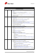
Introduction Version Date Remarks continued from last page V2.0.3 2013-Nov-27 • • • • • V2.0.4 2014-Feb-28 • • • • • • • V2.1.0 2014-Oct-07 • • • • • • • V3.0.
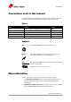
Introduction Conventions used in this manual To give this manual an easily understood layout and to emphasize important information, the following typographical styles and symbols are used: Styles Style Function Example Bold Courier Upper case Italics Parentheses and/or blue Programs, inputs or highlighting important things Code listings etc. Register Modes, fields Links bold Input REGISTER Mode (Link) Table 2: Styles Symbols Note This symbol highlights important information.
Introduction www www To download the GigE Installation Guide and GigE Camera and Driver Features, go to: http://www.alliedvisiontec.com/emea/support/downloads/ product-literature.html Software packages (including documentation and release notes) provided by Allied Vision can be downloaded from: http://www.alliedvisiontec.com/emea/products/ software.
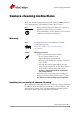
Camera cleaning instructions Camera cleaning instructions This chapter describes safety instructions/cautions valid for Mako cameras in case of cleaning lenses, optical filters/protection glass or sensors. Note • • Please read these instructions before you contact your Allied Vision camera dealer for assistance. Ask your Allied Vision camera dealer if you are not familiar with the procedures described below.
Camera cleaning instructions Figure 1: Illustration of camera orientation when removing lens or dust cap Is it an impurity? – Identifying impurities If you observe any image artefacts in your video preview of your Mako camera you may have impurities either on the lens, filter/protection glass, or on the sensor protection glass. Every Mako camera is cleaned prior to sealing and shipment; however, impurities may develop due to handling or unclean environments.
Camera cleaning instructions Please carefully remove the filter/protection glass and clean it on both sides using the techniques explained below. Note • • Taking out the filter requires special care. Ask your dealer to help you if you are not confident with the procedure. Figure 3: Removing IR cut filter/protection glass using special tools (P/N: E9020001 for 16mm filter and P/N: 3851 for 22 mm filter) 3.
Camera cleaning instructions 3. Wipe the glass surface with a spiral motion from the center to the rim. Normally, several spiral wipes are recommended. Wipe only on glass avoiding contact to metal surfaces, because microscopic dirt could be released and could cause scratches on the glass. 4. When you've finished cleaning, examine the surface in a strong light. Take an out-of-focus picture of a flat, illuminated surface to see if any dirt or dust remains. 5.
About Mako GigE cameras About Mako GigE cameras Mako GigE Mako cameras have a Gigabit Ethernet interface. GigE is the abbreviation for Gigabit Ethernet. All Mako cameras are GigE Vision V1.2 compliant cameras with Gigabit Ethernet interface. Mako cameras work with Gigabit Ethernet hardware and cable lengths up to 100 m. GigE Vision GenICam The GigE Vision standard is an interface standard for digital machine vision cameras widely supported in the industrial imaging industry.
Conformity Conformity Allied Vision Technologies declares under its sole responsibility that all standard cameras of the Allied Vision Mako family to which this declaration relates are in conformity with the following standard(s) or other normative document(s): • CE, following the provisions of 2004/108/EG directive • FCC Part 15 Class B • RoHS (2011/65/EU) • CE • WEEE We declare, under our sole responsibility, that the previously described Allied Vision Mako cameras conform to the directives of the CE.
Specifications Specifications Caution Before operating any Allied Vision camera, read the safety instructions and ESD warnings in the GigE Installation Guide. http://www.alliedvisiontec.com/emea/support/downloads/ product-literature/hardware-installation-guide.html Caution Due to the small packaging and high speed of Mako cameras, take care to ensure that the housing temperature of the camera does not exceed 45 °C.
Specifications Feature Specification On-board FIFO 64 MByte, up to 99 frames at full resolution, Mono8/Bayer8, and a GevSCPSPacketSize = 8192 bytes per packet Mono8, Mono12Packed, Mono12 BayerRG8, BayerRG12Packed, BayerRG12, Mono8, RGB8Packed, BGR8Packed, YUV411Packed, YUV422Packed, YUV444Packed Mono formats Color formats Exposure control Gain control Binning Decimation Opto-coupled I/Os Voltage requirements Power consumption Trigger latency* 83 μs to 2.
Specifications 60% Quantum Efficiency 50% 40% 30% 20% 10% 0% 350 500 650 800 Wavelength [nm] 950 1100 950 1100 Figure 7: Spectral sensitivity of Mako G-030B Red 45% Green Blue Quantum Efficiency 40% 35% 30% 25% 20% 15% 10% 5% 0% 350 500 650 800 Wavelength [nm] Figure 8: Spectral sensitivity of Mako G-030C Mako Technical Manual V3.0.
Specifications Mako G-032B/C Feature Specification Resolution Sensor Type Sensor size Cell size Lens mount Max frame rate at full resolution Max image bit depth On-board FIFO 658 x 492 SONY IT CCD ICX424AL/AQ with HAD microlens CCD Progressive Type 1/3 7.
Specifications 50% 45% Quantum Efficiency 40% 35% 30% 25% 20% 15% 10% 5% 0% 400 500 600 700 800 Wavelength [nm] 900 1000 Figure 9: Spectral sensitivity of Mako G-032B (without protection/cover glass) Red Green Blue 30% Quantum Efficiency 25% 20% 15% 10% 5% 0% 400 450 500 550 Wavelength [nm] 600 650 700 Figure 10: Spectral sensitivity of Mako G-032C (with IR cut filter) Mako Technical Manual V3.0.
Specifications Mako G-050B/C Feature Specification Resolution 812 x 614 Sensor SONY CCD ICX693ALA/AQA with Super HAD CCD II Type CCD Progressive Sensor size Type 1/3 Cell size 6.00 μm C / CS-Mount Lens mount Max frame rate at full resolution 71.
Quantum Efficiency Specifications 65% 60% 55% 50% 45% 40% 35% 30% 25% 20% 15% 10% 5% 0% 400 500 600 700 Wavelength [nm] 800 900 1000 Figure 11: Spectral sensitivity of Mako G-050B (without protection/cover glass) Red Green Blue 55% 50% Quantum Efficiency 45% 40% 35% 30% 25% 20% 15% 10% 5% 0% 400 450 500 550 Wavelength [nm] 600 650 700 Figure 12: Spectral sensitivity of Mako G-050C (without IR cut filter) Mako Technical Manual V3.0.
Specifications Mako G-095B/C Feature Specification Resolution Sensor Type Sensor size Cell size Lens mount Max frame rate at full resolution Max image bit depth On-board FIFO 1292 x 734 SONY IT CCD ICX692ALA/AQA with EXview HAD CCD II CCD Progressive Type 1/3 4.08 μm C / CS-Mount 42.
Specifications 70% Quantum Efficiency 60% 50% 40% 30% 20% 10% 0% 400 500 600 700 800 Wavelength [nm] 900 1000 Figure 13: Spectral sensitivity of Mako G-095B (without protection/cover glass) Red Green Blue 50% 45% Quantum Efficiency 40% 35% 30% 25% 20% 15% 10% 5% 0% 400 500 600 700 Wavelength [nm] 800 900 1000 Figure 14: Spectral sensitivity of Mako G-095C (without IR cut filter) Mako Technical Manual V3.0.
Specifications Mako G-125B/C Feature Specification Resolution Sensor Type Sensor size Cell size Lens mount Max frame rate at full resolution Max image bit depth On-board FIFO 1292 x 964 SONY IT CCD ICX445ALA/AQA with EXview HAD microlens CCD Progressive Type 1/3 3.
Specifications 60% Quantum Efficiency 50% 40% 30% 20% 10% 0% 400 500 600 700 Wavelength [nm] 800 900 1000 Figure 15: Spectral sensitivity of Mako G-125B (without protection/cover glass) Red Green Blue 40% Quantum Efficiency 35% 30% 25% 20% 15% 10% 5% 0% 400 450 500 550 Wavelength [nm] 600 650 700 Figure 16: Spectral sensitivity of Mako G-125C (with IR cut filter) Mako Technical Manual V3.0.
Specifications Mako G-131B/C Feature Specification Resolution Sensor Type Sensor size Cell size Lens mount Max frame rate at full resolution Max image bit depth On-board FIFO 1280 x 1024 e2v EV76C560 CMOS Progressive Type 1/1.8 5.
Specifications 70% Quantum Efficiency 60% 50% 40% 30% 20% 10% 0% 400 500 600 700 800 Wavelength [nm] 900 1000 900 1000 Figure 17: Spectral sensitivity of Mako G-131B Red 50% Green Blue Quantum Efficiency 45% 40% 35% 30% 25% 20% 15% 10% 5% 0% 400 500 600 700 800 Wavelength [nm] Figure 18: Spectral sensitivity of Mako G-131C Mako Technical Manual V3.0.
Specifications Mako G-192B/C Feature Specification Resolution Sensor Type Sensor size Cell size Lens mount Max frame rate at full resolution Max image bit depth On-board FIFO 1600 x 1200 e2v EV76C570 CMOS Progressive Type 1/1.8 4.
Specifications 35% Quantum Efficiency 30% 25% 20% 15% 10% 5% 0% 400 500 600 700 800 Wavelength [nm] 900 1000 900 1000 Figure 19: Spectral sensitivity of Mako G-192B Red Quantum Efficiency 30% Green Blue 25% 20% 15% 10% 5% 0% 400 500 600 700 800 Wavelength [nm] Figure 20: Spectral sensitivity of Mako G-192C Mako Technical Manual V3.0.
Specifications Mako G-223B/C (NIR) Feature Specification Resolution Sensor Type Sensor size Cell size Lens mount Max frame rate at full resolution Max image bit depth On-board FIFO 2048 x 1088 CMV2000 with microlenses and global shutter CMOS Type 2/3 5.5 μm C / CS-Mount 49.
Specifications Mako G-223 70% Mako G-223 NIR Quantum Efficiency 60% 50% 40% 30% 20% 10% 0% 400 500 600 700 Wavelength [nm] 800 900 1000 Figure 21: Spectral sensitivity of Mako G-223B (NIR) Red 50% Green Blue 45% Quantum Efficiency 40% 35% 30% 25% 20% 15% 10% 5% 0% 300 400 500 600 700 800 Wavelength [nm] 900 1000 1100 Figure 22: Spectral sensitivity of Mako G-223C (without IR cut filter) Mako Technical Manual V3.0.
Specifications Mako G-419B/C (NIR) Feature Specification Resolution Sensor Type Sensor size Cell size Lens mount Max frame rate at full resolution Max image bit depth On-board FIFO 2048 x 2048 CMV4000 with microlenses and global shutter CMOS Type 1 5.5 μm C / CS-Mount 26.
Specifications Mako G-419 Mako G-419 NIR 70% Quantum Efficiency 60% 50% 40% 30% 20% 10% 0% 400 500 600 700 Wavelength [nm] 800 900 1000 Figure 23: Spectral sensitivity of Mako G-419B (NIR) Red 50% Green Blue 45% Quantum Efficiency 40% 35% 30% 25% 20% 15% 10% 5% 0% 300 400 500 600 700 800 Wavelength [nm] 900 1000 1100 Figure 24: Spectral sensitivity of Mako G-419C (without IR cut filter) Mako Technical Manual V3.0.
Camera smart features Camera smart features Allied Vision cameras support a number of standard and extended features. The table below identifies a selection of interesting capabilities of the Mako camera family.
Filter and lenses Filter and lenses IR cut filter Color cameras are equipped with IR cut filter. The following illustration shows the spectral transmission of the IR cut filter: 1 0.9 Transmittance [T] 0.8 0.7 0.6 0.5 0.4 0.3 0.2 0.1 0 200 400 600 Wavelength [nm] 800 1000 Figure 25: Approximate spectral transmission of IR cut filter (may vary slightly by filter lot) (type Hoya C5000) Camera lenses Allied Vision offers different lenses from a variety of manufacturers.
Filter and lenses The following table lists selected image formats in width x height depending on camera type, distance and the focal length of the lens. Note • • Lenses with focal lengths < 8 mm may show shading in the edges of the image due to microlenses on the sensor. The exact values vary and depend on the respective lens. Mako G-030 Focal length for type 1/3 sensor Distance = 500 mm Distance = 1000 mm 4.8 mm 8 mm 12.
Filter and lenses Mako G-095 Focal length for type 1/3 sensor Distance = 500 mm Distance = 1000 mm 4 mm 6 mm 8 mm 10 mm 12 mm 16 mm 25 mm 1313 mm x 746 mm 873 mm x 496 mm 654 mm x 371 mm 522 mm x 296 mm 434 mm x 247 mm 324 mm x 184 mm 206 mm x 117 mm 654 mm x 371 mm 434 mm x 247 mm 324 mm x 184 mm 258 mm x 147 mm 214 mm x 122 mm 159 mm x 91 mm 100 mm x 57 mm Table 16: Focal length vs. field of view (Mako G-095) Mako G-125 Focal length for type 1/3 sensor 4.0 mm 4.
Filter and lenses Mako G-223 Focal length for type 2/3*sensors Distance = 500 mm Distance = 1000 mm 4.8 mm 1162 mm x 617 mm 6 mm 927 mm x 492 mm 6.
Camera dimensions Camera dimensions Note For information on sensor position accuracy (sensor shift x/y, optical back focal length z and sensor rotation ): see Appendix on page 76. Tripod adapter This tripod adapter (Allied Vision order number 4807) ... • ... can be used for Mako cameras. • ... is only designed for standard housings. 29.7 23.7 A 26 UNC 1/4-20 18.9 10.9 0 13 20 A M6 6 5 10 3.5 A-A Body size: 29.
Camera dimensions Cross section: C-Mount www Note • • Choose protection glass or filter according to the Modular Camera Concept: http://www.alliedvisiontec.com/us/support/downloads/ product-literature/avt-modular-concept.html Monochrome Mako cameras with serial number 536873083 or higher are shipped without a cover ring in the C-Mount thread. Refer to product change notice for more details. All color Mako cameras are equipped with the same IR cut filter type.
Camera dimensions Cross section: CS-Mount Choose protection glass or filter according to the Allied Vision Modular Concept. Download the Modular Concept at: http://www.alliedvisiontec.com/emea/support/downloads/ product-literature.html Filter 16 16 Maximum protrusion: 4.8 www CS-Mount Figure 29: CS-Mount dimensions for Mako G-030 / G-032 / G-050 / G-095 / G-125 / G-131 / G-192 (16 mm filter) Maximum protrusion: 5.8 18.
Camera dimensions Adjustment of the C-Mount and CS-Mount The dimensional adjustment cannot be done by the customer. All modifications have to be done by the Allied Vision factory. Note If you need any adjustments, please contact Customer Care: For phone numbers and e-mail: see Contacting Allied Vision on page 5. Mako standard housing 23.7 15 22 16.5 M2 - 2.2 (4x) 20 10 12 8.5 4.5 M3 - 2.3 (3x) 60.5 54.7 20 2.5 29 22.6 22.6 27 29 C-Mount 10.4 12.2 20 40.5 M2 - 4.5 (2x) M3 - 2.
Camera interfaces Camera interfaces This chapter describes the Gigabit Ethernet port, inputs and outputs, and trigger features. Note Read all Notes and Cautions in the GigE Installation Manual before using any interfaces. www For accessories like cables see: http://www.alliedvisiontec.com/emea/products/ accessories/gige-accessories.html Status LEDs LED2 (green) 8-pin camera I/O connector (+ ext.
Camera interfaces Gigabit Ethernet port The Gigabit Ethernet port conforms to the IEEE 802.31000BASE-T standard for Gigabit Ethernet over copper. To prevent EMI (electromagnetic interference) and for best performance, Category 6 (or higher) cables with S/STP shielding and connectors are recommended. Applications with longer cable lengths or harsh EMI conditions require Category 7 (or higher) cables. Note • • • • Cable lengths up to 100 m are supported.
Camera interfaces Mako input description Mako input block diagram External Internal 180R In1 Camera In GND Figure 34: Mako input block diagram The input can be connected directly to the system for voltages up to 24 V DC. An external resistor is not necessary. Mako delay and minimum pulse width Parameter Value Uin (low) 0–1.
Camera interfaces Mako output description Mako block diagram Internal External Camera Out Power Out1 R Out2 R Out3 R Figure 36: Mako output block diagram Caution • • Maximum 20 mA per output Camera Out Power 30 V may damage the camera Camera Out Power Resistor value* 5V 1.0 k 12 V 2.4 k 24 V 4.7 k at 5 mA minimum required current draw * Resistor required if Out1/2/3 connected to a device with < 5 mA draw, i.e.
Camera interfaces Optocoupler input (internal) IF 0 IC Optocoupler output (external) 100% 90% t 10% 0 td td tr ton (= td + tr) tr ts ton delay time rise time turn-on time toff tf t ts storage time tf fall time toff (= ts + tf) turn-off time Figure 38: Mako output switching times For all Mako models: Parameter and value td 1 μs tr 1 μs ton = td + tr 2 μs ts 26 μs tf 21 μs toff = ts + tf 47 μs (toff can deviate by 5 μs) Table 25: Parameters for Mako Test conditions Output: externa
Camera interfaces Control signals The inputs and outputs of the camera can be configured by software. The different modes are described below. Inputs Polarity selectable via software LP filter Input signal Optocoupler Input state Figure 39: Input block diagram Input/output pin control All input and output signals that pass the I/O connector are controlled by the I/O strobe commands. Outputs Output features are configured by software. Any signal can be placed on any output.
Camera interfaces Signal Description Imaging Imaging is high when the camera image sensor is either exposing and/or reading out data. Acquiring Active during an acquisition stream. SyncIn1 Active when there is an external trigger at SyncIn1. Strobe1 The output signal is controlled according to Strobe1 settings.
Camera interfaces Trigger timing diagram The following diagram explains the trigger concept in general. Note For trigger description on camera control basis, see GigE Camera and Driver Features. Readout time Trigger latency Tpd Registered exposure time Exposure start delay User trigger Note: Jitter at the beginning of an exposure has no effect on the length of exposure.
Camera interfaces Term Definition Trigger latency Time delay between the user trigger and the start of exposure Trigger jitter Error in the trigger latency time Trigger ready Indicates to the user that the camera will accept the next trigger Registered exposure time Exposure time value currently stored in the camera memory Exposure start delay Registered exposure time subtracted from the Readout time and indicates when the next exposure cycle can begin such that the exposure will end after the current r
Description of the data path Description of the data path The following diagrams illustrate the data flow and the bit resolution of the image data. The individual blocks are described in more detail in the GigE Camera and Driver Features document.
Description of the data path Mako G-131B, Mako G-192B Internal sensor components Sensor array Analog Reverse Analog Analog X/Y ROI Gain Offset Analog Analog ADC 10 bit Binning Frame 10 bit memory Gamma LUT 10 bit 10 bit 10 bit 12 ĺ 12 Defect mask 10 bit Decimation GigE HIROSE I/O Gigabit Ethernet interface 10 bit Camera control Figure 44: Block diagram of Mako G-131 and Mako G-192 monochrome cameras Mako G-223B, Mako G-223 NIR, Mako G-419B, Mako G-419 NIR Internal sensor components
Description of the data path Mako color cameras Mako with CCD sensors Mako G-032C, Mako G-050C, Mako G-095C, Mako G-125C Sensor Analog Vertical binning§ / Analog Vertical ROI Gain Offset White balance ADC Analog Analog 12 bit Horizontal ROI 12 bit Frame 8/12 bit memory Hue† Saturation 8 bit Color transformation Gamma LUT Bayer† 8 bit Interpolation 12 bit 12 bit 12 bit 12 ĺ 12 3X3 GigE HIROSE I/O Gigabit Ethernet interface 12 bit Camera control Horizontal binning§ § Color inform
Description of the data path Mako G-131C, Mako G-192C Internal sensor components Sensor array ROI Analog Analog Reverse Analog X/Y Gain Offset Analog Analog ADC 10 bit Binning 10 bit Decimation 10 bit Defect mask Frame 8/10 bit memory 8 bit Hue† Saturation Color transformation Bayer† 8 bit Interpolation 10 12bit bit 3X3 White balance Gamma LUT 10 bit 10 bit 12 ĺ 12 GigE HIROSE I/O Gigabit Ethernet interface 10 bit Camera control †For on-camera interpolated PixelFormats only—outpu
Description of the data path Camera features This chapter lists the camera and driver features for Mako cameras as displayed with the Vimba Viewer. www Hierarchy level 1 Acquisition For a detailed description of all GigE camera and driver controls, refer to the GigE Camera and Driver Features document: http://www.alliedvisiontec.com/fileadmin/content/PDF/ Software/Prosilica_software/Prosilica_firmware/ AVT_GigE_Camera_and_Driver_Features.
Description of the data path Hierarchy level 1 Hierarchy level 2 Hierarchy level 3 Hierarchy level 4 Off PreviousFrame TriggerSelector FrameStart AcquisitionStart AcquisitionEnd AcquisitionRecord TriggerSoftware TriggerSource Freerun Line1 FixedRate Software BufferHandlingControl (Vimba v1.
Description of the data path Hierarchy level 1 Hierarchy level 2 Hierarchy level 3 Hierarchy level 4 Continuous ExposureAutoControl ExposureAutoAdjustTol ExposureAutoAlg ExposureAutoMax ExposureAutoMin ExposureAutoOutliers ExposureAutoRate ExposureAutoTarget ExposureMode Timed TriggerWidth PieceWiseLinearHDR (available only on G-030) ExposureTimeAbs ExposureTimeIncrement ExposureTimePWL1 (available only on G-030) ExposureTimePWL2 (available only on G-030) ThresholdPWL1 (available only on G-030) Thresh
Description of the data path Hierarchy level 1 Hierarchy level 2 Hierarchy level 3 LUTLoadAll LUTMode Hierarchy level 4 Luminance Red Green Blue LUTSaveAll LUTSelector LUT1 LUTValue Saturation Whitebalance BalanceRatioAbs BalanceRatioSelector Red Blue BalanceWhiteAuto Off Once Continuous BalanceWhiteAutoControl BalanceWhiteAutoAdjustTol BalanceWhiteAutoRate DeviceStatus DeviceTemperature DeviceTemperatureSelector EventControl EventData EventAcquisitionEndFrameID EventAcquisitionEndTimestamp EventAcqui
Description of the data path Hierarchy level 1 Hierarchy level 2 Hierarchy level 3 Hierarchy level 4 EventLineRisingEdgeFrameID EventLineRisingEdgeTimestamp EventOverflowFrameID EventOverflowTimestamp EventID EventAcquisitionEnd EventAcquisitionRecordTrigger EventAcquisitionStart EventError EventExposureEnd EventFrameTrigger EventFrameTriggerReady EventLine1FallingEdge EventLine1RisingEdge EventLine2FallingEdge EventLine2RisingEdge EventLine3FallingEdge EventLine3RisingEdge EventLine4FallingEdge EventLi
Description of the data path Hierarchy level 1 Hierarchy level 2 Hierarchy level 3 Persistent Default Gateway Persistent IP Address Persistent Subnet Mask Hierarchy level 4 StreamBytesPerSecond StreamFrameRateConstrain StreamHold StreamHoldCapacity StreamHoldEnable Off On Timestamp GevTimestampControlLatch GevTimestampControlReset GevTimestampTickFrequency GevTimestampValue IO Strobe StrobeDelay StrobeDuration StrobeDurationMode Source Controlled StrobeSource AcquisitionTriggerReady FrameTriggerReady F
Description of the data path Hierarchy level 1 Hierarchy level 2 Hierarchy level 3 Hierarchy level 4 SyncOut3 SyncOutSource GPO AcquisitionTriggerReady FrameTriggerReady Exposing FrameReadout Imaging Acquiring LineIn1 Strobe1 ImageFormat Height HeightMax ImageSize OffsetX OffsetY PixelFormat Width WidthMax ImageMode BinningHorizontal BinningHorizontalMode Sum Average BinningVertical BinningVerticalMode Sum Average DecimationHorizontal DecimationVertical ReverseX ReverseY SensorHeight SensorWidth Info D
Description of the data path Hierarchy level 1 Hierarchy level 2 DeviceScanType DeviceVendorName FirmwareVerBuild FirmwareVerMajor FirmwareVerMinor SensorBits SensorType Hierarchy level 3 Hierarchy level 4 SavedUserSets UserSetDefaultSelector Default UserSet1 UserSet2 UserSet3 UserSetLoad UserSetSave UserSetSelector Default UserSet1 UserSet2 UserSet3 Stream Info GSVP Filter Version Multicast MulticastEnable Multicast IP Address Settings GSVP Adjust Packet Size GSVP Burst Size GSVP Driver Selector GSVP
Description of the data path Hierarchy level 1 Hierarchy level 2 Hierarchy level 3 Stat Frames Rescued Stat Frames Shoved Stat Frames Underrun Stat Local Rate Stat Packets Errors Stat Packets Missed Stat Packets Received Stat Packets Requested Stat Packets Resent Stat Time Elapsed Hierarchy level 4 StreamInformation (Vimba v1.3 or higher) StreamID StreamType Table 28: Available Mako camera and driver features Frame memory An image is normally captured and transported in consecutive steps.
Resolution and ROI frame rates Resolution and ROI frame rates This section charts the resulting frame rate from changing sensor height from full image to a single line. Unless otherwise noted, sensors do not give an increase in readout speed with a reduction in width. Note • • • Data was generated using StreamBytesPerSecond = 124 MB/s (full bandwidth) and an 8-bit pixel format. Frame rates may be lower if using network hardware incapable of 124 MB/s.
Resolution and ROI frame rates Mako G-030B/C: ROI frame rates 1 Max. frame rate = -------------------------------------------------------------------204 μs + 6.
Resolution and ROI frame rates Mako G-032B/C: ROI frame rates 1 Max. frame rate of CCD = -----------------------------------------------------------------------------------------------------------------------------------------------------19.46 μs ROI height + 2.29 μs 492 – ROI height + 195.81 μs Formula 2: Mako G-032: theoretical maximum frame rate of CCD Maximum frame rate at full resolution according to formula: 102.
Resolution and ROI frame rates Mako G-050B/C: ROI frame rates 1 Max. frame rate of CCD = -----------------------------------------------------------------------------------------------------------------------------------------------------22.53 μs ROI height + 5.32 μs 614 – ROI height + 193.63 μs Formula 3: Mako G-050: theoretical maximum frame rate of CCD Maximum frame rate at full resolution according to formula: 71.
Resolution and ROI frame rates Mako G-095B/C: ROI frame rates 1 Max. frame rate of CCD = -----------------------------------------------------------------------------------------------------------------------------------------------------31.54 μs ROI height + 4.87 μs 734 – ROI height + 219.97 μs Formula 4: Mako G-095: theoretical maximum frame rate of CCD Maximum frame rate at full resolution according to formula: 42.
Resolution and ROI frame rates Mako G-125B/C: ROI frame rates 1 Max. frame rate of CCD = -----------------------------------------------------------------------------------------------------------------------------------------------------34.01 μs ROI height + 3.09 μs 964 – ROI height + 176.42 μs Formula 5: Mako G-125: theoretical maximum frame rate of CCD Maximum frame rate at full resolution according to formula: 30.
Resolution and ROI frame rates Mako G-131B/C: ROI frame rates Frame rate [fps] 2000 200 20 0 150 300 450 600 Height [pixels] 750 900 1050 Figure 55: Frame rates Mako G-131 as function of ROI height [width=1280] ROI height Width* Frame rate 1024 960 768 720 512 480 360 240 120 60 30 15 1280 1280 1280 1280 1280 1280 1280 1280 1280 1280 1280 1280 62 66 82 87 121 129 170 249 462 809 1295 1798 Table 35: Frame rates (fps) of Mako G-131 as function of ROI height (pixel) [width=1280] *There will
Resolution and ROI frame rates Mako G-192B/C: ROI frame rates Frame rate [fps] 2000 200 20 0 200 400 600 Height [pixels] 800 1000 1200 Figure 56: Frame rates Mako G-192 as function of ROI height [width=1600] ROI height 1200 1024 960 768 720 512 480 360 240 120 60 30 16 Width* 1600 1600 1600 1600 1600 1600 1600 1600 1600 1600 1600 1600 1600 Frame rate 60 70 75 93 99 138 147 193 282 525 919 1470 2042 Table 36: Frame rates (fps) of Mako G-192 as function of ROI height (pixel) [width=1600] *Ther
Resolution and ROI frame rates Mako G-223B/C: ROI frame rates Frame rate [fps] 5000 500 50 5 0 100 200 300 400 500 600 Height [pixels] 700 800 900 1000 1100 Figure 57: Frame rates Mako G-223 as function of ROI height ROI height 1088 1000 900 800 700 600 500 400 300 200 100 50 20 10 5 2 1 Width* 2048 2048 2048 2048 2048 2048 2048 2048 2048 2048 2048 2048 2048 2048 2048 2048 2048 Frame rate 49.5 53.8 59.7 67.1 76.6 89.2 106.8 132.9 176.1 260.8 502.1 934.6 1933.8 2847.3 3624.5 4906.7 4926.
Resolution and ROI frame rates Mako G-419B/C: ROI frame rates Frame rate [fps] 5000 500 50 5 0 300 600 900 1200 Height [pixels] 1500 1800 2100 Figure 58: Frame rates Mako G-419 as function of ROI height ROI height 2048 2000 1800 1600 1400 1200 1000 800 600 400 200 100 50 20 10 5 2 Width* 2048 2048 2048 2048 2048 2048 2048 2048 2048 2048 2048 2048 2048 2048 2048 2048 2048 Frame rate 26.3 26.9 29.9 33.6 38.4 44.8 53.7 66.9 88.8 132.1 257.7 490.8 895.9 1775.5 2639.2 3486.7 4342.
Appendix Sensor position accuracy of Mako cameras D Camera body Pixel area Pixel area y Camera body Sensor case Sensor case x Figure 59: Allied Vision sensor position accuracy Method of positioning Optical alignment of the photo sensitive sensor area into the camera front module (lens mount front flange). Reference points Sensor: center of the pixel area (photo sensitive cells). Camera: Center of the camera front flange (outer case edges).
Index Index A F acquiring (signal) .................................... 50 acquisition stream ................................... 50 AcquisitionTriggerReady (signal) ................ 49 FCC Class B ............................................. 15 focal length ............................................ 37 frame readout ......................................... 49 frame trigger .......................................... 49 FrameReadout (signal) ............................. 49 FrameTrigger (signal) ....
Index O Output block diagram ............................... 50 Output signals ......................................... 49 Output switching times ............................. 48 outputs .................................................. 49 OutVCC ................................................... 47 P PoE ....................................................... 45 propagation delay (trigger) ....................... 51 R reading out data (trigger) .......................... 52 readout (definition) .....