
Instruction manual
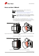
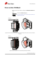
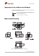

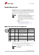
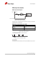

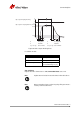
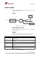
Table Of Contents
- Contacting Allied Vision
- Introduction
- Camera cleaning instructions
- About Mako GigE cameras
- Conformity
- Specifications
- Camera smart features
- Filter and lenses
- Camera dimensions
- Camera interfaces
- Description of the data path
- Resolution and ROI frame rates
- Appendix
Mako Technical Manual V3.0.0
45
Camera interfaces
Gigabit Ethernet port
The Gigabit Ethernet port conforms to the IEEE 802.31000BASE-T standard for
Gigabit Ethernet over copper. To prevent EMI (electromagnetic interference)
and for best performance, Category 6 (or higher) cables with S/STP shielding
and connectors are recommended. Applications with longer cable lengths or
harsh EMI conditions require Category 7 (or higher) cables.
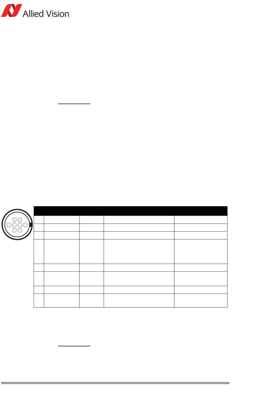
Mako I/O connector pin assignment
The General Purpose I/O port uses a Hirose HR25-7TR-8PA(73) connector on the
camera side. The mating cable connector is Hirose HR25-7TP-8S.
Note
• Cable lengths up to 100 m are supported.
• The 8-pin RJ-45 jack provides a pin assignment according
to the Ethernet standard (IEEE 802.3 1000BASE-T).
• All Mako cameras are PoE capable (802.3af/at).
• If both interfaces are used for power (I/O and GigE con-
nector via PoE), the camera will only use the power from
the I/O connector.
Accessories
• Cables are available from Allied Vision:
http://www.alliedvisiontec.com/emea/products/
accessories/gige-accessories.html
Figure 33: Camera I/O connector pin assignment
Note
The cable side Hirose connector is available for purchase
from Allied Vision.
P/N: K7600503
2
5
4
7
13
68
Pin Signal Direction Level Description
1 Out 1 Out Open emitter, max. 20 mA Output 1
2 Out 2 Out Open emitter, max. 20 mA Output 2
3 Out 3 Out Open emitter, max. 20 mA Output 3
4In 1 In U
in
(high) = 3.0–24.0 V
up to 36 V with external resistor
of 3.3 k in series
U
in
(low) = 0–1.0 V
Input 1
5 Camera In GND In --- GND for input
6 Camera Out
Power
In Common VCC for outputs max.
30 V DC
Power input for opto-
isolated outputs
7 Camera Power --- 12–24 V DC +/- 10% Camera power supply
8 Ext GND --- GND for ext. Power External Ground for
external Power