
Instruction manual


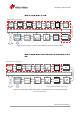
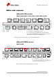

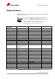

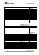
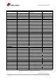
Table Of Contents
- Contacting Allied Vision
- Introduction
- Camera cleaning instructions
- About Mako GigE cameras
- Conformity
- Specifications
- Camera smart features
- Filter and lenses
- Camera dimensions
- Camera interfaces
- Description of the data path
- Resolution and ROI frame rates
- Appendix
Mako Technical Manual V3.0.0
53
Description of the data path
Description of the data path
The following diagrams illustrate the data flow and the bit resolution of the
image data. The individual blocks are described in more detail in the GigE Cam-
era and Driver Features document.
Mako monochrome cameras
Mako with CCD sensors
Mako G-032B, Mako G-050B, Mako G-095B, Mako G-125B
Mako with CMOS sensors
Mako G-030B
Figure 42: Block diagram of Mako monochrome cameras with CCD sensors
Figure 43: Block diagram of Mako G-030 monochrome cameras
Sensor
12 bit
12 bit
HIROSE I/O
GigE
Analog
12 bit
Gamma
12 bit
LUT
12 ĺ 12
Vertical
binning /
Vertical ROI
12 bit
Horizontal
binning
Horizontal
ROI
12 bit
Analog
Gain
Camera control
Analog Analog
ADC
Oset
Frame
memory
Gigabit
Ethernet
interface
HIROSE I/O
12 bit
12 bit
Gigabit
Ethernet
interface
12 bit
LUT
12 ĺ 12
12 bit
Gamma
12 bit
Frame
memory
GigE
‡
Factory calibrated. NOT a user control.
Sensor
array
Analog Analog
Analog
Internal sensor components
Analog
Oset
Sensor
System
Gain
‡
Sensor
System
Oset
‡
Analog
Vertical
ROI
ADC
12 bit
Defect
mask
Gain
Analog
Analog
Decimation
12 bit
Horizontal
ROI
HDR
Analog
Reverse
X/Y
Camera control