
Instruction Manual


Camera interfaces
Goldeye Technical Manual V2.5.0
39
The current (1) that flows through the optocoupler and the integrated dropping
resistor should be > 5 mA and should not exceed 20 mA.
Input pin 9:
open/GND means continuous operation
5 V ... 20 V means image on demand
Trigger input (pin 10, 11)
This input allows control of the electronic shutter by an externally applied sig-
nal. It is necessary to switch the camera into image-on-demand mode to enable
direct exposure control. For more information see chapter IOD mode (CC4) on
page 48.
The image acquisition is started with approximately 1 μs delay due to the rising
edge of the pulse at the trigger input. There might be an additional delay, see
table Camera standard feature: AcquisitionControl on page 46.
The current (1) that flows through the optocoupler and the integrated dropping
resistor should be > 5 mA and should not exceed 20 mA.
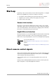
Figure 9: Mode input diagram
Note
This signal is internally combined with the camera control sig-
nal CC1 over an OR gate. For more information: see chapter
Trigger input (CC1) on page 44.
Figure 10: Trigger input diagram